 Products Home / Custom Solutions & Manufacturing Capabilities / Piezoelectric Motors, Elliptec® Technology: OEM and Manufacturing Capabilities
Piezoelectric Motors, Elliptec® Technology: OEM and Manufacturing Capabilities

Please Wait
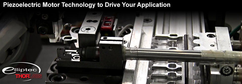
Elliptec® Piezoelectric Motor Technology for Your OEM Application
Thorlabs’ multidisciplinary OEM applications engineering team is ready to design and build a custom Elliptec piezoelectric motor solution for your application. The highly dynamic and high-precision Elliptec motors are favored for their simplicity of assembly and operation, as well as their compact dimensions, light weight, and low power consumption (see the Technical Data tab). Our Multi-Position Sliders and Linear Stages showcase the smooth linear movement enabled by these piezo resonant motors and demonstrate that they are ideally suited for integration into a wide variety of end-applications, including those requiring the actuation of shutters and lids, the adjustment of beam-deflection mirror alignment, the toggling of locks, or the selective engagement of filters. In addition, Thorlabs’ automated manufacturing facility in Dortmund, Germany enables the high-volume production of motors capable of meeting your needs.
By working closely with you, each integration is tailored to meet the specific complexity, dimensional, and pricing requirements of the application. Thorlabs’ team is experienced in implementing a range of design solutions, from the most basic mechanical sub-assembly to fully self-contained electromechanical assemblies with integrated drive electronics. In addition to performing custom design and manufacturing services, Thorlabs can complete final assembly and functionally test every OEM unit before shipping.
Thorlabs takes pride in meeting the unique needs of your OEM application. Each project begins with a dedicated account manager establishing a strong collaborative relationship between your team and the technical resources at Thorlabs. Discussions with you are held to establish detailed design specifications, define performance goals, and identify system requirements. Thorlabs uses this information to propose the most appropriate custom design and associated manufacturing solution.
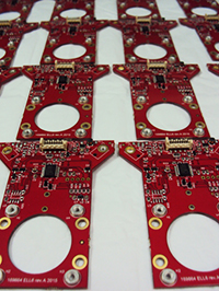
Custom Product PCBs Before
Motor Integration
Finished designs, based on modelling results, describe the manufacturing process and specify the constituent materials. Three-dimensional mechanical modeling for the project is performed using computer-aided design (CAD) software, and mechanical stress analysis is conducted using the software’s associated finite element analysis (FEA) tools. Based on the requirements of your application, electronics schematics are generated and board layouts are designed, such as the boards shown in the image at left. Thorlabs has the ability to model the mechanical components and the electronics together, which produces truly integrated designs. Materials and associated manufacturing techniques are carefully chosen to suit the application, as these have a direct influence on the operation and cost of the assembly. Candidate materials for component fabrication include both metals and plastics, and Thorlabs routinely designs for a wide variety of manufacturing techniques including machining, molding, and casting. The Implementations tab highlights these capabilities by including summaries of and links to products based on the Elliptec motor.
Please contact us today to discuss integrating the exceptional Elliptec motion control motor technology into your application.
Introduction to the Elliptec Motor
At the core of the Elliptec piezoelectric resonant motor is the piezo element, which is press-fit into an aluminum motor frame. The frame is more than just a physical housing; it is also a resonator and a transducer, and it has been designed specifically to interface with the piezoelectric element (see The Elliptec® Motor tab for additional details). During operation of the motor, the oscillations of the driven piezoelectric element are amplified by the frame and converted to an elliptical motion at the frame's tip. An attached spring presses the machined tip of the frame into firm contact with the driven element, which may be a rotor or other component. Power is supplied to the piezoelectric element through wires soldered to its upper and lower surfaces. The motor's direction of motion is changed and its speed is tuned by adjusting the ultrasonic frequency of the applied signal. The orientations of the spring and wire leads are chosen to suit the application, as are the lengths of the wire leads and whether or not they are terminated.
Highlighted Features
The Elliptec piezoelectric motors are designed to perform with precision, be highly responsive, and possess the flexibility to allow them to be customized for a range of applications. Features of the motors include:
- Lightweight: 1.2 g
- Non-Magnetic Components
- Quiet Operation
- Option for Battery-Powered Operation for Portable and/or In-Field Use
The performance of the Elliptec resonant motor when it is integrated into an application is highly dependent on the design characteristics of the total system. Integrated electromechanical assembly designs that load the motor and incorporate closed-loop operation have been demonstrated to achieve or implement:
- High Resolution: 0.5 µm
- Excellent Positional Repeatability: 3 µm
- High Speed: 300 mm/s (Equivalent to Speed During No-Load Operation)
- Power-Aware Bus Arbitration
- Self-Testing Electronics
- Upgradable Firmware
- USB Connection to Deliver the Control Signal and Supply Power
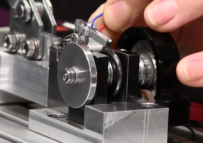
Click to Enlarge
Installation of the Elliptec Motor into a Test Fixture
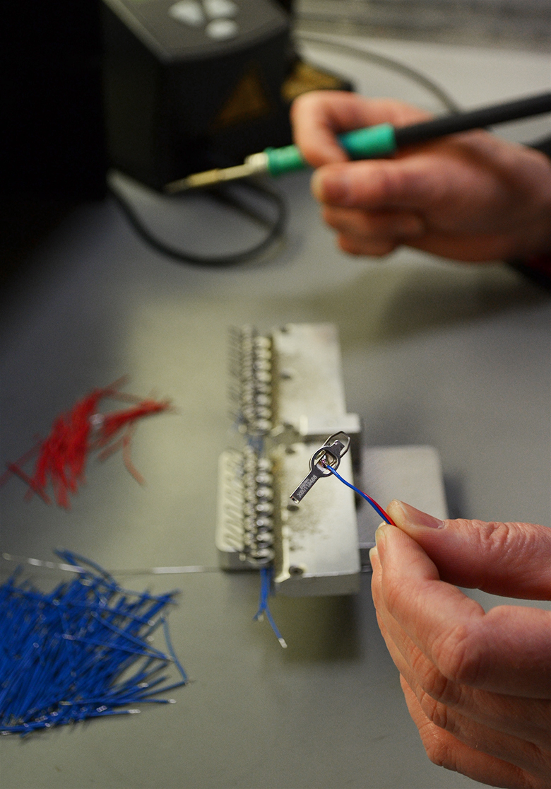
Click to Enlarge
Soldering Leads to the Piezoelectric Element of the Elliptec Motor
General Specifications for the Unloaded Elliptec® Motor, Open-Loop Configuration
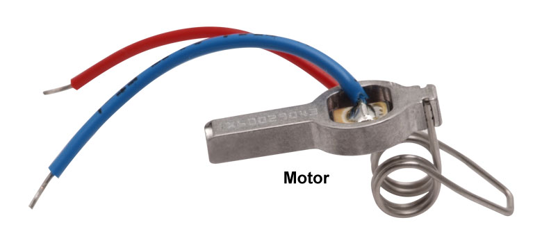
The specifications listed here describe the typical characteristics of the Elliptec piezoelectric resonant motor, when it is operated under open-loop and unloaded conditions. The motor is shown being held, by the wire leads soldered to its piezoelectric element, in the image at right. The majority of applications employing the motor will incorporate it into an application and operate it under loaded conditions. When this is the case, the performance of the motor is highly dependent on the design characteristics of the system. For example, implementing the loaded motor in a closed-loop system can achieve a positional resolution of 0.5 µm, while the step size of the unloaded motor running under open-loop conditions is 10 µm. Please see the Overview and Implementations tabs for discussion of the performance that can be achieved when the motor is operated under loaded and closed-loop conditions. The piezoelectric resonant motors integrated into all designs share dimensional, weight, and frequency response characteristics.
| Parameter | Specification |
|---|---|
| Length (Frame with Piezoelectric Element, Without Spring) | 20 mm (0.79") |
| Width (Frame with Piezoelectric Element, Without Spring) | 8 mm (0.32") |
| Height (Frame with Piezoelectric Element, Without Spring) | 4 mm (0.16") |
| Weight | 1.2 g (0.042 oz) |
| Frequency for Forward-Motion Operation | 73 to 84 kHz (80 kHz Typical) |
| Frequency for Reverse-Motion Operation | 91 to 108 kHz (100 kHz Typical) |
| Step Size (Unloaded, Open-Loop) | 10 µm (0.00039") |
| Response Time (Unloaded, Open-Loop) | <100 µs |
| Speed (Unloaded, Open-Loop) | 300 to 550 mm/s (350 mm/s Typical) [11.8 to 21.7 in/s (13.8 in/s Typical)] |
| Force Applied by Motor (Unloaded, Open-Loop) | 0.2 N (0.045 lb) |
| Unpowered Holding Force (Unloaded, Open-Loop) | 0.5 to 1.2 N (0.8 N Typical) [0.11 to 0.27 lb (0.18 lb Typical)] |
| Current to Driver Electronics (Depends on Motor Speed) | Up to 450 mA (5 V Supply Voltage) |
| Signal Voltage Amplitude at Motor | 5 to 8 V (Square Wave) 5 to 10 V (Sinusoidal Wave) |
| Elliptec Resonant Motor Products | |
|---|---|
| Item # | Description |
| ELL6K | Dual-Position Slider for Two SM1-Threaded Optics |
| ELL9K | Four-Position Slider for Four SM1-Threaded Optics |
| ELL12K | Six-Position Slider for Six SM05-Threaded Optics |
| ELL17K | 28 mm Linear Travel Stage |
| ELL20K | 60 mm Linear Travel Stage |
| ELL18K | Rotation Stage |
| ELL14K | SM1-Threaded Rotation Mount |
Products Based on the Elliptec® Motor
Thorlabs is developing a line of open-frame products based on the Elliptec piezoelectric resonant motor, which are ideal for both incorporation into OEM applications and laboratory use. As these products are released, they will be listed in the table at right and highlighted in the descriptions below. Click on a link in the table to be taken to the respective product's page. All of these products are complete packages that include the interface board, cables, and power supply (when required for operation). Other characteristics common to all include:
- Being Ideally Suited for OEMs and Applications Requiring Rapid Switching
- Micro-B USB and Picoflex®1 Connectors for Control Signals
- Support of Multi-Drop Serial Communication Protocol
Control the movement of any of these devices by pressing buttons on the interface board, through computer control via the Elliptec software package that is available for download, or by sending simple signals to digital lines on the device PCB.
Multiple Elliptec devices can be controlled using the ELLB Bus Distributor or by splicing multiple connectors onto one ribbon cable. A single bus distributor can connect up to four Elliptec devices; up to 16 devices can be connected if the buses are daisy chained. This bus can be controlled one of three ways: through an interface board (included with the bundles below) to connect to a PC running the Elliptec software, by connecting to an Arduino®2 or Raspberry Pi®3 board, or by wiring the connector pins to a user-supplied control board. Alternatively, up to 16 devices can be spliced onto a single ribbon cord. The devices can then be simultaneously controlled by the interface board or selectively controlled by the Elliptec software. See each device's manual for instruction on how to splice multiple devices onto a ribbon cord and their respective Pin Diagrams tab for pin assignments when making custom connections.
- Picoflex is a registered trademark of Molex Incorporated.
- Arduino is a registered trademark of Arduino Sa Société Anonym (SA).
- Raspberry Pi is a registered trademark of the Raspberry Pi Foundation.
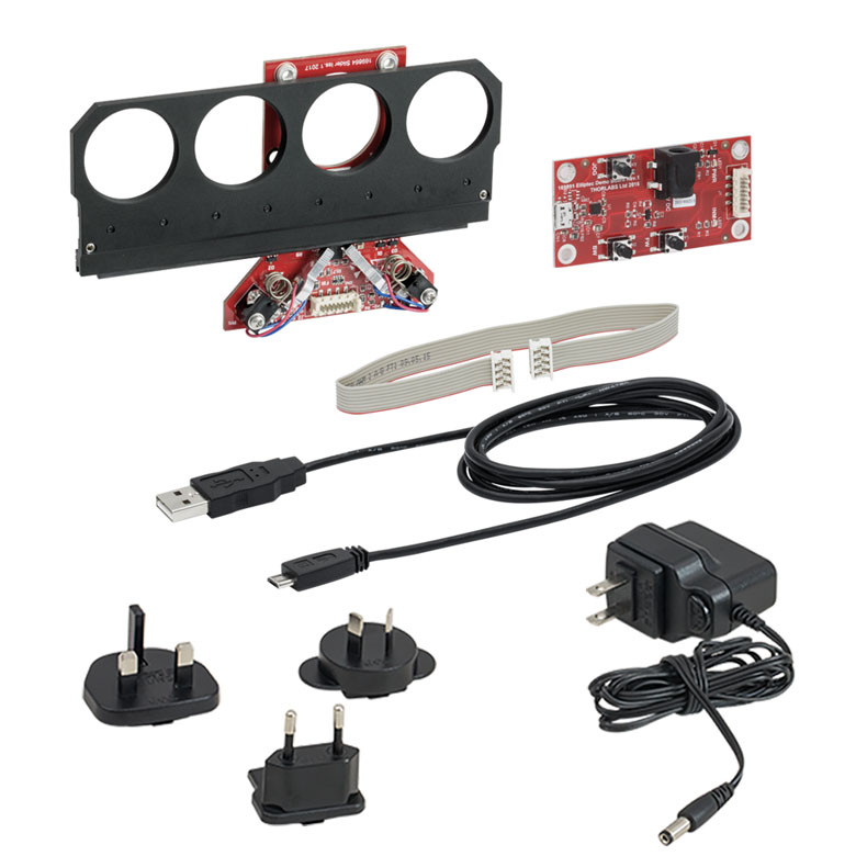
| The ELL6K Bundle | The ELL9K Bundle | The ELL12K Bundle |
|---|---|---|
| Dual-Position Slider | Four-Position Slider | Six-Position Slider |
| Interface Board | ||
| Mini-B to A-Type USB Cable | ||
| 8-Conductor 28 AWG Flat Ribbon Cable | ||
| PC-Based Software for Download | ||
| - | 5 V Power Supply | 5 V Power Supply |
| Key Specificationsa | |||
|---|---|---|---|
| Item # | ELL6K | ELL9K | ELL12K |
| Ports for Mounted Optics | Two SM1 Threaded | Four SM1 Threaded | Six SM05 Threaded |
| Threaded Port Separation, Max | 31 mm (1.22") | 93 mm (3.66") | 95 mm (3.73") |
| Positioning Repeatability | <100 µm (30 µm Typical) | ||
| Switching Time Range | 180 to 270 ms | 450 to 500 ms | 350 to 400 ms |
| Maximum Total Load | 0.150 kg (0.331 lbs) | ||
| DC Voltage Input | 4.5 to 5.5 V | ||
| Weight (Slider Only) | 44 g (0.097 lbs) |
70.0 g (0.154 lbs) | 78.5 g (0.173 lbs) |
| Minimum Lifetime | 3.3 Million Switching Operations or 100 km Total Travel | ||
Sliders for Switching Among SM05- or SM1-Mounted Optics
- Mount up to Six SM05-Threaded Optics or up to Four SM1-Threaded Optics
- Photo-Interrupter Optical Sensor Technology for Precise Positioning
- Compatible with 30 mm Cage System Components
Thorlabs' ELL6K Dual-Position, ELL9K Four-Position, and ELL12K Six-Position Slider packages are designed to exchange mounted optics for one another in an optical path. The ELL6K and ELL9K mount two and four SM1-threaded optics, respectively, while the ELL12K mounts six SM05-threaded optics. All sliders are lightweight and compact, with the six-position slider weighing 78.5 g and having dimensions of 143.5 mm x 77.7 mm x 14.2 mm when the carriage is in one of the end positions. The ELL6 features one Elliptec motor, while the ELL9 and ELL12 have two of these highly dynamic motors. As they have no gearing, the motors can stop within microseconds. This allows the motors to respond quickly to signals from the photoelectric sensor and accurately position the slider. In addition, the motors include no magnets, which makes them compatible with EM-sensitive environments. The contents of the ELL9K bundle are pictured at the right, and components included with the ELL6K, ELL9K, and ELL12K are listed in the table at the right.
The movement of the slider may be controlled by pressing buttons on the remote handset, through computer control via the Elliptec software package that is available for download, or by sending simple signals to digital lines on the slider board. The ELL6K dual-position, ELL9K four-position, and ELL12K six-position sliders are well suited as filter changers, and the ELL6K may also be used as a shutter. The sliders possess SM05-threaded (0.535"-40) or SM1-threaded (1.035"-40) bores, with 3.5 mm deep threads, at each position. Four 4-40 tapped holes on the PCB allow the sliders to be mounted with and integrated into optical setups using Thorlabs' 30 mm Cage System.
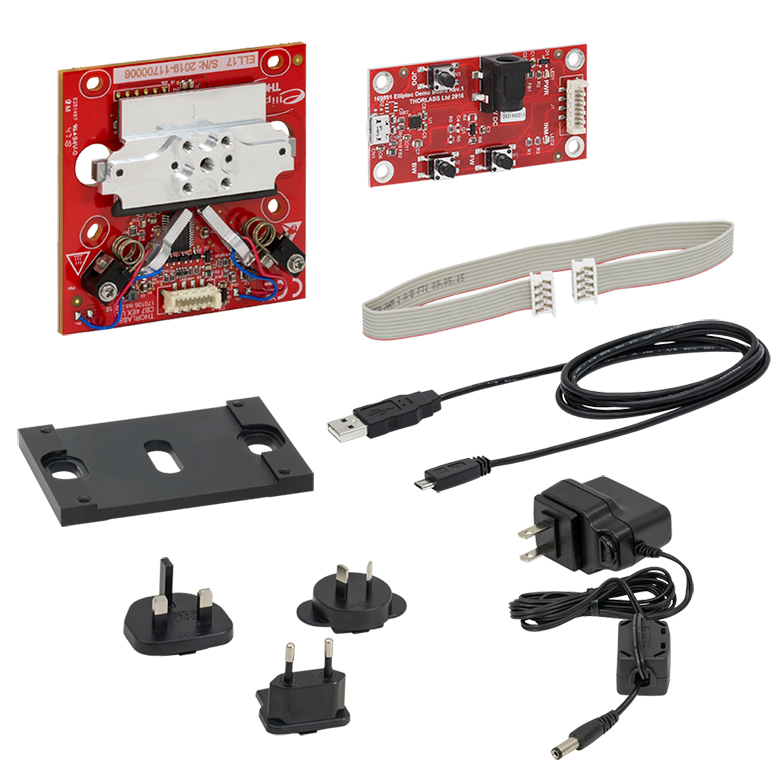
| The ELL17K(/M) Bundle | The ELL20K(/M) Bundle |
|---|---|
| 28 mm Stage | 60 mm Stage |
| Interface Board | |
| Mounting Bracket | |
| Mini-B to A-Type USB Cable | |
| 8-Conductor 28 AWG Flat Ribbon Cable | |
| PC-Based Software for Download | |
| 5 V Power Supply | |
| Key Specificationsa | ||
|---|---|---|
| Item # | ELL17K(/M) | ELL20K(/M) |
| Travel | 28.0 mm (1.1") | 60.0 mm (2.4") |
| Positioning Accuracy | 50 µm | |
| Homing Accuracy | 20 µm | |
| Repeatability (100 g Load) | 20 µm | |
| Maximum Velocity (No Load) | 180 mm/s | 90 mm/s |
| Maximum Total Load | 200 g (0.441 lbs) | |
| DC Voltage Input | 4.5 to 5.5 V | |
| Weight of Stage and Bracket | 0.076 kg (0.168 lbs) | 0.104 kg (0.229 lbs) |
| Minimum Lifetimeb | 100 km of Travel | |
Linear Translation Stages
- 28 mm or 60 mm Linear Translation
- Magnetic Incremental Linear Encoder
- Compatible with MMP1 (MMP1/M) or RB13P1 (RB13P1/M) Top Plates
Thorlabs' ELL17K(/M) and ELL20K(/M) Linear Stage Bundles are designed to be a compact solution for OEM applications requiring linear movement. The ELL17K provides 28 mm of travel and the ELL20K provides 60 mm. Both stages are lightweight and compact, with the 60 mm stage weiging 0.069 kg and requiring no more than 162.3 mm x 67.0 mm of space to accomodate the PCB and the full travel range of the stage. The stages feature two Elliptec motors. As they have no gearing, the motors can stop within microseconds. This allows the motors to respond quickly to signals from the photoelectric sensor and accurately position the stage. The contents of the ELL17K(/M) bundle are pictured at the right, and components included with the ELL17K(/M) and ELL20K(/M) are listed in the table at the right.
The movement of the stage may be controlled by pressing buttons on the remote handset, through computer control via the Elliptec software package that is available for download, or by sending simple signals to digital lines on the stage board. The stage features one 8-32 (M4) tapped hole and four 4-40 (M3) tapped holes for mounting posts or MMP1(/M) or RB13P1(/M) top plates. The mounting bracket that comes with each kit has two slots for use with 1/4"-20 (M6) screws for mounting to an optical table or breadboard.
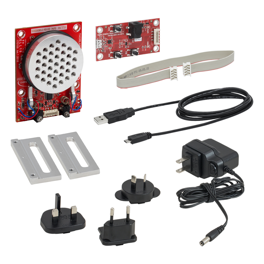
| The ELL18K(/M) Bundle |
|---|
| Rotation Stage |
| Interface Board |
| 2 Mounting Brackets |
| Mini-B to A-Type USB Cable |
| 8-Conductor 28 AWG Flat Ribbon Cable |
| PC-Based Software for Download |
| 5 V Power Supply |
| Key Specificationsa | |
|---|---|
| Item # | ELL18K(/M) |
| Travel (No Limit Switches) | 360° Continuous |
| Homing Repeatability | 1.75 mrad (0.1°) |
| Bidirectional Repeatability | 873 µrad (0.05°) |
| Velocity (Maximum) | 430 °/s |
| Maximum Total Load | 200 g (7.05 oz) |
| DC Voltage Input | 4.5 to 5.5 V |
| Weight (Without Mounting Brackets) | 90 g (3.17 oz) |
| Minimum Lifetime | 100 km (600 600 Revolutions) |
Click to see the Separate Components of the ELL18K(/M) Bundle
Assembled Components of the ELL18K(/M) Bundle
Rotation Stage
- 360° Continuous Rotation
- Ø50 mm Rotation Stage with Closed-Loop Positioning
- 8-32 (M4) Taps for Component Mounting
Thorlabs' ELL18K(/M) Rotation Stage Bundle is designed to be a compact solution for applications requiring rotational control. The Ø50 mm rotation stage has 37 8-32 (M4) tapped holes for mounting optomechanics or custom assemblies. With a mass of 90 g and maximum dimensions of 81.0 mm x 60.0 mm x 20.3 mm, the rotation stage is lightweight and compact. The stage features two Elliptec motors. As they have no gearing, the motors can stop within microseconds. This allows the motors to respond quickly to signals from the photoelectric sensor and accurately position the stage. The contents of the ELL18K(/M) bundle are pictured at the right, and the components included are listed in the table at the right.
The movement of the stage may be controlled by pressing buttons on the remote handset, through computer control via the Elliptec software package that is available for download, or by sending simple signals to digital lines on the stage board. Each bundle comes with two mounting brackets which provide slots for 1/4"-20 (M6) screws for mounting to an optical table or breadboard.
A filter wheel adapter (Item # ELLA2), with 12 SM05-threaded (0.535"-40) holes for holding filters, is also available for use with the ELL18(/M) rotation stage.
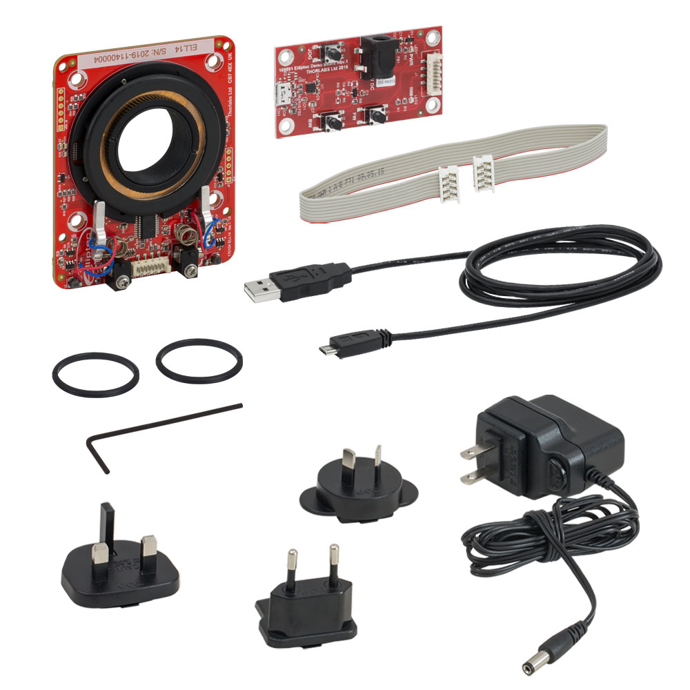
| The ELL14K Bundle |
|---|
| Rotation Mount |
| Interface Board |
| Mini-B to A-Type USB Cable |
| 8-Conductor 28 AWG Flat Ribbon Cable |
| PC-Based Software for Download |
| 5 V Power Supply |
| Key Specificationsa | |
|---|---|
| Item # | ELL14K |
| Travel (No Limit Switches) | 360° Continuous |
| Homing Repeatability | 1.75 mrad (0.1°) |
| Bidirectional Repeatability | 873 µrad (0.05°) |
| Velocity (Maximum) | 430 °/s |
| Maximum Total Load | 50 g (1.76 oz) |
| DC Voltage Input | 4.5 to 5.5 V |
| Weight | 80 g (2.82 oz) |
| Minimum Lifetime | 100 km (>600 000 Revolutions) |
Rotation Mount
- 360° Continuous Rotation
- SM1-Threaded Rotation Mount for Ø1" or 25 mm Optics
Thorlabs' ELL14K Rotation Mount Bundle is designed to be a compact solution for applications requiring optic rotation. The rotating cell of each mount is internally SM1 (1.035"-40) threaded and includes two SM1RR retaining rings for mounting Ø1" or Ø25.0 mm optics as well as optics in SM1-threaded lens tubes. With a mass of 80 g and dimensions of 66.0 mm x 82.5 mm x 19.0 mm, the rotation mount is lightweight and compact. The mount features two Elliptec motors. As they have no gearing, the motors can stop within microseconds. This allows the motors to respond quickly to signals from the photoelectric sensor and accurately position the mount. The contents of the ELL14K bundle are pictured at the right, and the components included are listed in the table at the right.
The movement of the mount may be controlled by pressing buttons on the remote handset, through computer control via the Elliptec software package that is available for download, or by sending simple signals to digital lines on the mount board.
Click to Enlarge
The Components of the Elliptec Motor
Click to Enlarge
The Elliptec Piezoelectric Resonant Motor
The Elliptec® Piezoelectric Resonant Motor
Thorlabs' Elliptec® piezo resonant motor, shown at right, is lightweight, with a mass of 1.2 g, and compact: the dimensions of the resonator housing, excluding the spring, are 8 mm x 4 mm x 20 mm.
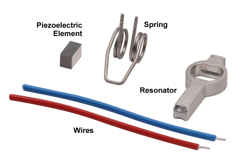
Components of the Motor
The components that compose the motor are shown at far-right. The piezoelectric element is press fit into the aluminum resonator, which has been precisely designed and machined to produce the desired elliptical motion at the tip and to interface optimally with the driven module. The free ends of the spring are integrated with the resonator housing. The wires, which are soldered to the top and bottom of the piezoelectric element, deliver the voltage signal that induces the piezoelectric element to vibrate at ultrasonic frequencies.
When the motor is built into a system, the open loop of the spring is bolted to a sturdy surface that is stationary with respect to the item to be driven, and the tip of the resonator is placed in contact with the item. The purpose of the spring is to maintain constant contact between the tip of the resonator and the driven item, and the direction of motion is determined by the resonance frequency at which the piezo element is driven.
Elliptical Motion and Comparison with Conventional Motors
The motor is operated by driving it at one of its two resonance frequencies. A voltage signal oscillating at an ultrasonic frequency is applied to the piezoelectric chip, which responds by expanding less than a micron and then contracting back to its original dimensions at the frequency of the driving signal. This rapid-cycling change in the chip's dimensions causes a vibration in the aluminum resonator housing. When the vibration is at one of the housing's resonance frequencies, a pushing motion results at the tip of the motor. When the vibration is at the other resonance frequency a pulling motion results.
As illustrated in the video, the pulling and pushing motions result from the tip of the motor tracing an elliptical path in space when the motor operates at resonance. The selected resonance frequency controls the direction of the cyclical motion. The motor's tip traces one half of the ellipse as it expands and the other half as it contracts. When the motor pushes the driven item, the motor's tip is in contact with the item while the tip expands; the two are not in contact while the tip contracts. The converse is true when the motor pulls the driven item in the opposite direction. The total displacement at the tip of the motor is a function of both the mechanical load it is driving and the voltage supplied to the piezo element. The maximum displacement can be up to a few microns when the peak driving voltage is 5 V.
The motor behaves in many ways like a DC or electromagnetic stepper motor, but it does not suffer from many of the drawbacks of these conventional motors. Unlike conventional electromagnetic motors, which must overcome inertial delays to come to a stop, the highly dynamic Elliptec motor can stop within microseconds. As it has no gears, it does not exhibit backlash. Since it possesses no magnets, it is compatible with use in environments sensitive to electromagnetic interference. The motion of the driven element is continuous and smooth. As the tip of the motor must be in contact with the driven item to induce motion, the motor possesses the safety feature of an inherent friction brake. When in contact with a plastic surface, the motor operates virtually silently.
For OEM applications, the motor can be manufactured in volume at low cost, and it can be driven by inexpensive analog electronics. It does not require microprocessors or software; however it is compatible for use with them.
| Posted Comments: | |
Francesco Lena
(posted 2024-04-03 05:41:54.087) Dear, I'm interested in the ressonant motor for an cryogenic stage application. Do you have more info regarding the use in cryo conditions? Any user case in this field? Best regards spolineni
(posted 2024-04-08 09:18:22.0) Thank you for your interest in our resonant motors. I will be in touch with you directly to share our insights on the operation of these motors under low-temperature conditions Andreas B
(posted 2023-11-02 14:32:31.89) Hi,
We bought an Elliptec multi-positioner filter mount. It worked fine to start with but now suddenly gives "Sensor error". Any thought on how to adress this issue? do'neill
(posted 2023-11-06 06:25:36.0) Response from Daniel at Thorlabs. This is caused by the motor not reaching the correct position or not being able to sense the starting position. One of the first things you can do is frequency scan the device and gently and carefully clean the rail with IPA. I will reach out to you directly to troubleshoot this with you. frank Heine
(posted 2019-12-04 17:22:38.89) Hi Thorlabs Team.
I am interested in the run length of the elliptec motor under vacuum conditions. Would be great to have some numbers as this motor is of interest for applications in our portofolio, especially for compact low cost laser com terminals.
Best regards
Frank Heine
Head of Laser Systems Development cwright
(posted 2019-12-05 09:10:05.0) Response from Charles at Thorlabs: Hello Frank, thank you for your feedback. I will reach out to your directly to discuss what information we have on this and see how we may be able to support you. aqeel.ahmed
(posted 2019-02-08 12:46:54.133) Hi, We are using several of elliptec rotation motors and one of them malfunctioned recently. Is is possible for the motor to be replaced or repaired? rmiron
(posted 2019-02-11 10:04:25.0) Response from Radu at Thorlabs: Hello, Aqeel. Unfortunately we can't replace those stages at the moment, but we can still repair them, depending on what the issue is. I will contact you directly in order to troubleshoot your device. moritz.kuerten
(posted 2018-09-10 18:50:00.49) Hello,
I own several Märklin railway models with this fantastic motor. Is it possible to purchase some of them as spare part in case of an defect? AManickavasagam
(posted 2018-09-12 03:34:53.0) Response from Arunthathi @ Thorlabs: Thanks for your query. I have spoken to our Elliptec team regarding your requirement and you will be contacted directly. jgrav2001
(posted 2018-06-15 15:50:04.52) Running the Elliptec motor at 80khz in the air without an external load. Is the sound silent? rmiron
(posted 2018-06-20 09:34:05.0) Response from Radu at Thorlabs: The motor may or may not be noisy at 80kHz. If it is driven at its optimal frequency, then it is silent. If not, then it can emit an irritating noise. The optimal frequency depends on multiple factors, including load and mechanical variances. If the default value makes the stage noisy, then I recommend you sent a _HOSTREQ_SEARCHFREQ_MOTOR command, followed by a _HOSTREQ_SAVE_USER_DATA command. This will re-set the driving frequency of the motor and amend the problem. jgrav2001
(posted 2018-06-13 03:58:51.917) Unloaded Elliptec™ Motor
What are the prices for the motors? AManickavasagam
(posted 2018-06-15 07:16:13.0) Response from Arunthathi at Thorlabs: Thanks for your inquiry, I will contact you directly regarding your requirements and discuss pricing. mhadmack
(posted 2017-12-15 13:55:42.993) What material is used for the Elliptec spring? Can a fully non-magnetic/non-ferrous version be made? AManickavasagam
(posted 2018-01-02 06:40:23.0) Response from Arunthathi at Thorlabs: Thanks for your query.
The Elliptec motor has a ferromagnetic spring, as it is the integral part of the motor we are unable to custom make or replace the spring to make a non-magnetic version. |