 Products Home / Custom Solutions & Manufacturing Capabilities / Custom Benchtop Enclosures Manufacturing
Custom Benchtop Enclosures Manufacturing

Please Wait
Thorlabs' Manufacturing Technology and Services
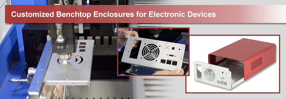
Thorlabs offers fully customizable benchtop enclosures for electronic devices. Our services include laser cutting, riveting, UV printing, and overlay custom molding. Customization options are available for the front panel, rear panel, mounting board (the Assembly Details tab identifies each of these components), and an optional overlay. Read below or watch the video to the right to learn more about each service, all of which are performed in-house at our Shanghai, China facility.
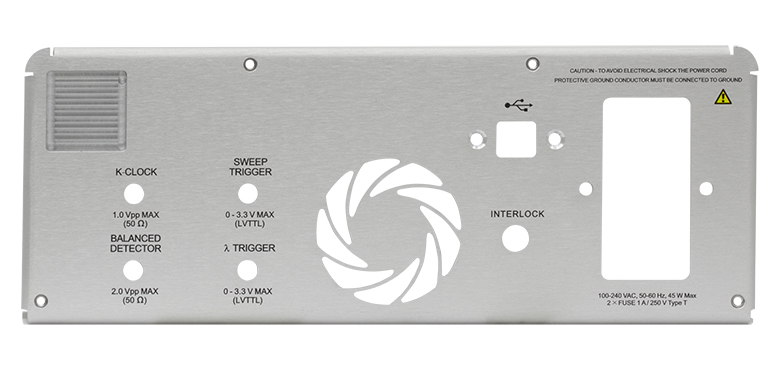
To begin ordering a custom benchtop enclosure, please refer to the configurator on the Custom Enclosures tab to fill out a request form. Shown below are examples of customized enclosure front plates.
Laser Cutting
Our CNC-operated, high-power laser cutter features a maximum cutting area of 600 x 600 mm and can cut through carbon steel, stainless steel, aluminum alloy, and brass, as well as a variety of other materials. Thorlabs' all-aluminum benchtop enclosures include front and rear panels as well as a mounting board, all of which can be customized to virtually any shape or design.
Riveting
After components of the enclosure are laser cut, the panels are riveted. This process involves mechanically clinching cylindrical fasteners to the panel, providing stability when assembling the panels and serving as points of contact for PCBs or other electronic devices housed within the enclosure. Riveting can be performed on any panel of the enclosure. Please note that overlays cannot be riveted.
UV-LED Printing
UV-LED inkjet printing has an advantage over mechanical engraving in that ink is applied to the surface and does not penetrate the material. The ink dries immediately upon exposure to UV light, providing labels that are both clean and smooth. UV printing can be performed on any panel of the enclosure.
Overlays
If an overlay is desired for the front panel of your enclosure, we can provide a custom mold. Using 4-color UV printing, overlays are constructed from 1 mm polycarbonate plastic to provide greater durability and resistance to impurities, and they can be designed to fit virtually any shape or cutout. Thorlabs utilizes this process to design the front panels of our Kurios® bandpass filters.
Assembly Details for Blank Enclosures
The blank enclosures are shipped completely assembled with the exception of the two foldable feet and two fixed feet. The feet can be easily attached using the included M3 cap screws and 3/32" hex key. The mounting boards are sold separately, and four M3 button head screws (5/64" hex) are included with the enclosure for installing a mounting board. The enclosure can be disassembled for ease of machining. The included 5/64" and 3/32" hex keys can be used for all screws in the assembly.
| Ref. # | Component | Qty. | Material | Color/Finish |
|---|---|---|---|---|
| 1 | Front Panel | 1 | Aluminum | Silver/Anodized |
| 2 | Bottom | 1 | ||
| 3 | Mounting Boarda | 1a | Hair-Line Finish | |
| 4 | Cover | 1 | Gray or Red/Anodized | |
| 5 | Trim Strip | 1 | Silver/Anodized | |
| 6 | Gusset | 4 | Plain | |
| 7 | Foldable Feet | 2 | ABS Plastic | Black |
| 8 | Fixed Feet | 2 | Black | |
| 9 | M3 Screw (5/64" and 3/32" Hex Keys Included) |
Varies | Stainless Steel | Plain |
| 10 | Rear Panel | 1 | Aluminum | Silver/Anodized |
| Mounting Boarda | |||||||
|---|---|---|---|---|---|---|---|
| Ref. # | Item # | Compatible Enclosure |
Width | Depth | Height | Material | Color/Finish |
| 3 | EC1515MB | EC1515A(R) | 130.0 mm (5.12") |
80.0 mm (3.15") |
1.5 mm (0.06") | Aluminum | Hair-line Finish |
| EC1530MB | EC1530A(R) EC1530B(R) |
130.0 mm (5.12") |
200.0 mm (7.87") |
||||
| EC2030MB | EC2030A(R) EC2030B(R) |
180.0 mm (7.09") |
200.0 mm (7.87") |
||||
| EC2530MB | EC2530C(R) | 230.0 mm (9.06") |
200.0 mm (7.87") |
||||
| EC2530BBb | (9.06") |
(9.06") |
9.5 mm (0.37") | ||||
Custom Enclosures Request Form
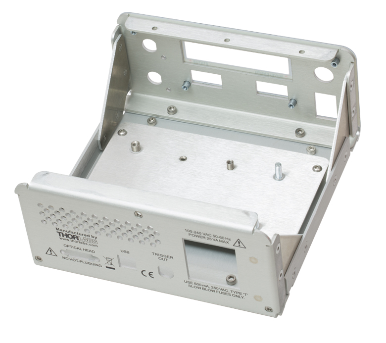
Click to Enlarge
Customized Enclosure with Lid Removed
Use the configurator below to customize your own benchtop electronics enclosure. Customization options are available for the front panel, rear panel, mounting board, and overlay (not included with standard enclosures). The drawing in the Assembly Details tab identifies each of these parts, with the exception of the overlay. Click on the ![]() icons in the custom enclosure tool below for information on each customizable part of the enclosure, as well as the customization options for that part. Click on the yellow boxes below to view details about the cutting, riveting, and UV printing services.
icons in the custom enclosure tool below for information on each customizable part of the enclosure, as well as the customization options for that part. Click on the yellow boxes below to view details about the cutting, riveting, and UV printing services.
After selecting one of our standard enclosure sizes, check the boxes corresponding to the service you would like for each section of the enclosure. For each service selected, download the .pdf or .dxf template(s) for that section of the enclosure, edit the template with your desired design, and then upload the file (.pdf only) by clicking on the Upload button. You can view a design file that you have uploaded by clicking the icon in the Preview column.

Click to Enlarge
Example of a Customized Enclosure
You can add multiple enclosures of the same kind by increasing the Quantity, shown below the table in the configurator. You can customize multiple enclosures with different sizes and different designs by clicking the Add Another Enclosure button at the bottom. Once all customization requests have been entered, click Add to Cart.
Click on the yellow boxes below to learn more about the customization services we offer.
Laser Cutting
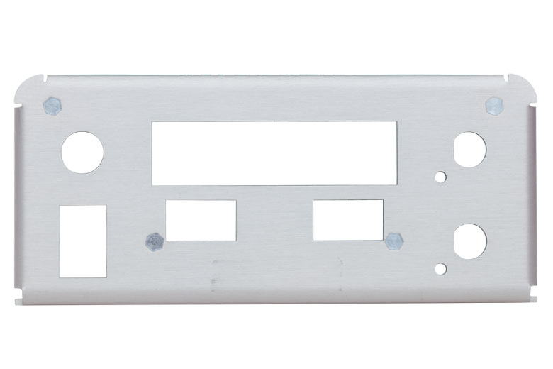
Click to Enlarge
Example of Cutting on the Front Panel
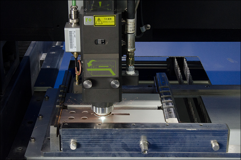
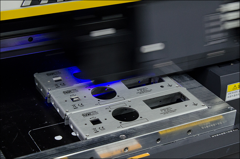
Click to Enlarge
Laser Cutting in Progress
Custom cutouts can be made on the front and back panels of the enclosure as well as on the mounting board. All the cutouts are performed by solid state fiber lasers, which offer both higher precision and higher speed compared to traditional CO2 laser cutting technology.
Drawings can be submitted as a .pdf document. All drawings will be processed at a 1:1 scale.
| Specifications | |
|---|---|
| Dimensional Tolerance | ±0.05 mm |
| Positioning Precision | ±0.2 mm |
| Minimum Cutout Size | Ø1.5 mma |
Riveting
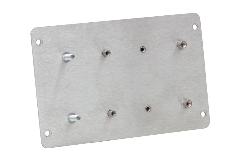
Click to Enlarge
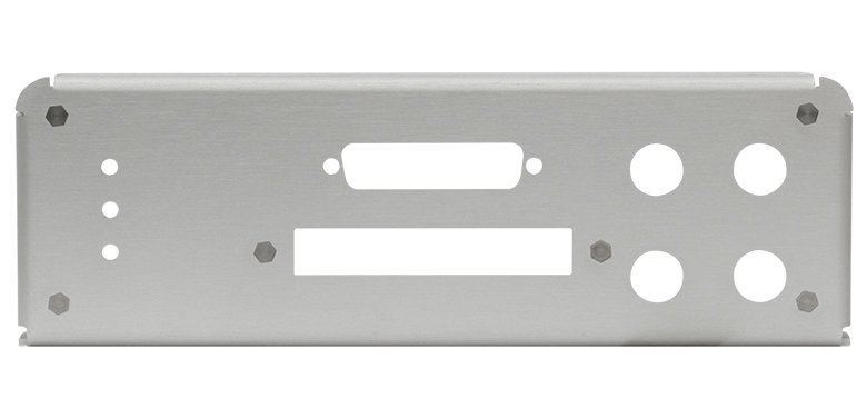
Example of Riveting on the Mounting Board
| Specificationsa | |
|---|---|
| Positioning Precision | ±0.3 mm |
Riveting involves attaching a self-clinching standoff, stud, or nut onto the panels or mounting board of the enclosure. These can be used as additional mounting locations for components inside the enclosure.
Please specify the position and type of all riveting locations on your drawing. The riveting requests should be made on the same drawing file as the cutting requests. Drawings can be submitted as a .pdf document. All drawings will be processed at a 1:1 scale.
Click here to view the riveting components available for these enclosures.
For parts that are not on this list, please contact Tech Support for availability and lead time.
UV Printing
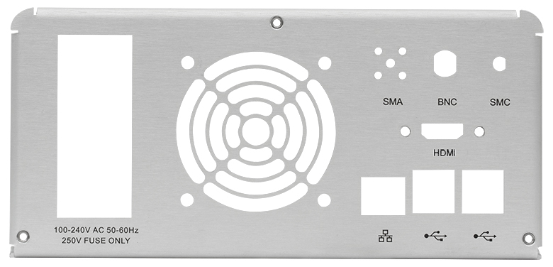
We use 4-color digital printing with UV-cured ink to add markings to the front and back panel, as well as the mounting board. As an alternative to traditional silk screening and engraving, UV printing is versatile and has the ability to produce high resolution, high quality, full color marking on both metal and plastic surfaces. The hard UV-cured ink also provides excellent chemical resistance to solvents such as ethanol.
Click to Enlarge
UV Printing in Progress
Drawings can be submitted as a .pdf document. Pictures are recommended to be in vector format for best results. All drawings will be processed on a 1:1 scale. All colors will be printed as they are in the drawings; we do not accept black and white drawings with color codes.
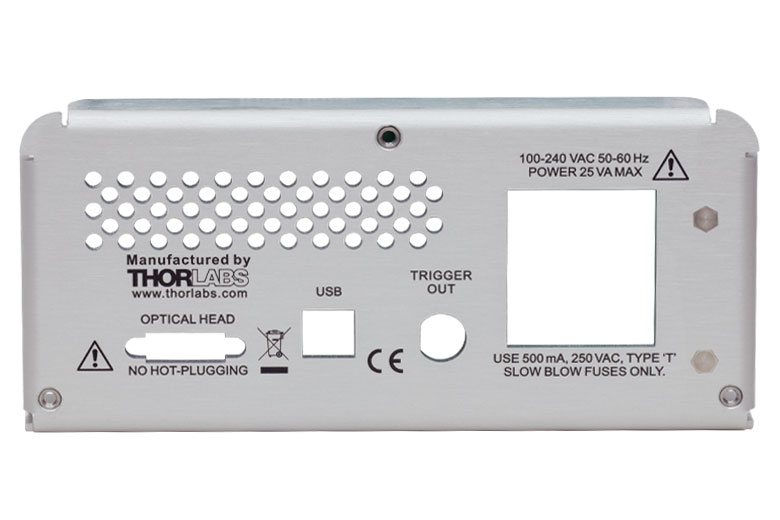
Click to Enlarge
Example of UV Printing on the Back Panel
| Specifications | |
|---|---|
| Printing Type | 4-Color Printing |
| Resolution | 1440 x 1200 dpi |
| Minimum Font Size | 2 pt |
| Dimensional Tolerance | ±0.25 mm |
| Positioning Precision | ±0.3 mm |
| Printable Surfaces | Front Panel (Outer Surface)a; Rear Panel (Outer Surface)a; Mounting Board |
Overlay
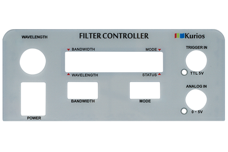
Click to Enlarge
Example of a Customized Overlay
| Specifications | |
|---|---|
| CNC Cutting | |
| Dimensional Tolerance | ±0.05 mm |
| Positioning Precision | ±0.05 mm |
| Minimum Cutout Size | Ø1 mm |
| UV Printing | |
| Printing Type | 4-Color Printing |
| Resolution | 1440 x 1200 dpi |
| Minimum Font Size | 2 pt |
| Dimensional Tolerance | ±0.25 mm |
| Positioning Precision | ±0.3 mm |
For customized enclosures, we provide a plastic overlay to be attached to the front panel. The overlay is 1 mm thick transparent polycarbonate with an adhesive back side. The overlay can be customized with high-precision CNC cutting and UV printing.
Two drawings are required for each overlay: one for cutting and the other for UV printing. The drawing requirements are the same as those for the laser cutting and UV printing outlined above.
Due to tolerancing, we suggest that the cutouts in the overlay be 0.5 mm smaller than the cutouts on the front panel.
Riveting is not available on the overlay.
| Posted Comments: | |
user
(posted 2022-03-18 20:06:05.103) Dear Sir or Madam,
I am Ke, from Optilab in Phoenix.
I am wondering if Thorlabs is selling 3U rackmount, with the appearance looks like your TLX3 tunable laser source housing?
(As shown in the link: https://www.thorlabs.com/newgrouppage9.cfm?objectgroup_id=14587)
We want to buy some for housing our own products.
Thanks! jdelia
(posted 2022-03-25 02:48:39.0) Thank you for contacting Thorlabs. I have reached out to you directly to discuss your application and our custom capabilities. Payam Rabiei
(posted 2020-08-27 19:41:59.03) Do you provide custom enclosure with other dimensions. We need a box that is ~300mmx250mmx50mm. We can provide the box if you can provide the UV printing and cutting and riveting YLohia
(posted 2020-09-04 10:11:09.0) Hello, thank for contacting Thorlabs. Custom items can be requested by emailing techsupport@thorlabs.com. We will reach out to you directly to discuss the possibility of offering this customization. |