 Products Home / Actuators, Adjusters, & Transducers / Piezoelectric Chips and Stacks / Piezoelectric Benders
Piezoelectric Benders

- Low-Voltage Bimorph Benders with 150 V Max Voltage
- Sub-Millisecond Response Time
- ±135 µm and ±450 µm Maximum Displacement
- Available with or without Holder
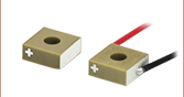
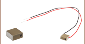
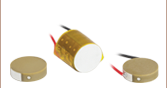
PB4VB2W
Piezoelectric Bimorph Bender
with Wires, ±135 µm Displacement
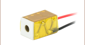
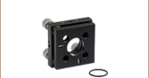
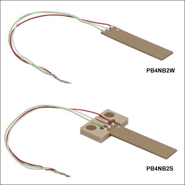
PB4NB2S
Piezoelectric Bimorph Bender with Wires and Holder, ±450 µm Displacement
Holder with Two Ø4.3 mm Through Holes for Mounting the Piezoelectric Bender
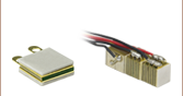
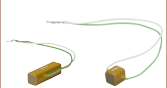
PB4NB2W
Piezoelectric Bimorph Bender
with Wires, ±450 µm Displacement
32 mm
(28 mm Active)
20 mm
(16 mm Active)


Please Wait
| Piezo Selection Guide |
|---|
| Piezoelectric Ceramic Chips |
| Square |
| Square with Through Hole |
| Round |
| Ring |
| Tube |
| Shear |
| Benders |
| Single-Crystal Piezoelectric Chips |
| Square |
| Piezoelectric Stacks |
| Mounted Piezoelectric Actuators |
| Ultrasonic Piezo Chips & Transducers |
| Vibrating Piezo Actuator |
| Webpage Features | |
|---|---|
| Clicking this icon below will open a window that contains item specific specifications and mechanical drawings. | |
Click to Enlarge
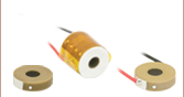
These bimorph piezoelectric benders flex when a voltage is applied. Please see the Operation tab for details.
Features
- Sub-Micron Resolution
- Two Displacement Options Available:
- 16 mm Active Free Length, ±135 µm Displacement
- 28 mm Active Free Length, ±450 µm Displacement
- Drive Voltage Range: 0 to 150 V
- Ideal for OEM Applications
- Available with or without a Pre-Attached PEEK Holder
Thorlabs' Piezoelectric Benders provide a tip deflection whose magnitude and direction is a function of the applied bias voltages. This is useful for applications such as wire bonding, electrical switches, beam deflection, valves, and acceleration sensors. Featuring either a 16 mm or 28 mm active free length, these bimorph benders provide displacements of up to ±135 µm and ±450 µm, respectively.
The piezo benders include three pre-soldered wire leads, and are available without a holder or pre-mounted in a rigid PEEK (polyether ether ketone) holder. For more information on mounting recommendations for the bare piezos, see the Operation tab. The pre-attached PEEK holder features two Ø4.3 mm through holes on 12.5 mm centers that accept 8-32, M3, or M4 screws. This holder it is not detachable.
Click to Enlarge

Click to Enlarge
Piezo Operation
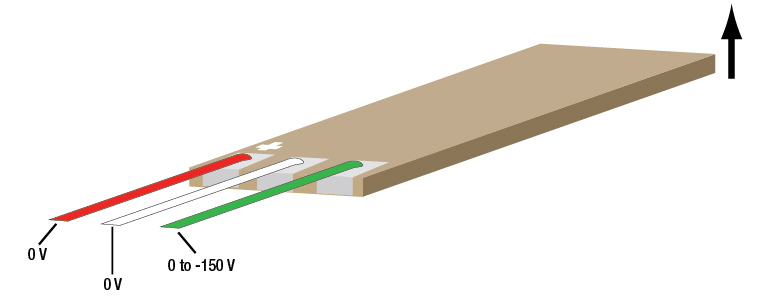
These benders are constructed of multiple, co-fired piezoceramic layers, in which the voltage bias across the top half of the layers is controlled independently of the voltage bias across the bottom half of the layers. The length of the layers increases as the voltage applied across them increases. Tip deflection of the bender occurs when the top and bottom sets of layers elongate by different amounts. For example, downward displacement of the bimorph bender occurs when the top layer elongates while the length of the bottom layer remains the same.

Any voltage driver with a voltage limit of at least 150 V can be used to drive these piezo bender actuators. Electrical connections to the three electrodes are located on the top surface, and each electrode is connected to a wire lead; the electrode connected to the red lead should always be positively biased and is marked with a silver plus sign. Providing a bias over only the top or bottom layers can be used to operate the bender in single-side voltage control mode, when deflection is limited to one direction. Providing different bias over these two sets of layers enables deflection in either direction. Examples of these cases are shown below. Do not apply a voltage bias in excess of 150 V between any two leads, as this can damage the bender. For details on the different voltage control modes, see the Operation tab.
Note: The bare piezoelectric actuators are compatible with vacuum environments of >10-7 Torr. The versions pre-attached to a PEEK holder are not recommended for use in vacuum environments.
Piezoelectric benders with custom dimensions and voltage ranges are available. Additionally, we support high-volume orders. Please contact Tech Support for more information.

Click to Enlarge
Dicing the PZT Block into Individual Elements

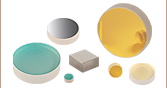
Click to Enlarge
Chips After Binder Burnout and Sintering
Thorlabs' In-House Piezoelectric Manufacturing
Our piezoelectric chips are fabricated in our production facility in China, giving us full control over each step of the manufacturing process. This allows us to economically produce high-quality products, including custom and OEM devices. A glimpse into the fabrication of our piezoelectric chips follows. For more information about our manufacturing process and capabilities, please see our Piezoelectric Capabilities page.
- Build Blocks from Flexible Sheets of Lead Zirconate Titanate (PZT) or BiScO3-PbTiO3 (BSPT) Powder
- Screen Print Electrodes on Each Individual Sheet
- Layer the Printed Sheets One Top of Another
- Consolidate the Layered Sheets in an Isostatic Press
- Dice the Block into Individual Elements
- Purge Solvent and Binder Material Residues by Heat Treating the Elements
- Sinter the Elements to Fuse the Piezoelectric Pressed Powder and Grow PZT or BSPT Crystals
- Lap the Elements to Achieve Tight Dimensional Tolerances: ±5 µm for Each Element
- Screen Print the Outer Electrodes on the Elements
- Align the Individual PZT or BSPT Crystals Along the Same Axis by Poling the Elements
Click to Enlarge
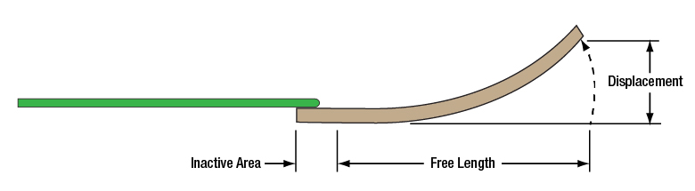
Figure 1: The active area, which expands in response to the applied voltage, is measured from the end of the piezo towards the silver plus sign. The inactive area does not respond to the applied voltage.
Operation Notes
Mounting
Thorlabs' piezoelectric bimorph benders are offered with or without a holder for mounting. The PB4VB2W and PB4NB2W, which come without a holder, can be mounted either by mechanical clamping or gluing.
We recommend attaching the piezo bending actuator to a rigid holder (ceramic, PEEK, etc.) in order to maintain elastic compliance and avoid additional drift cause by deformation of the holder. When selecting a holder, ensure that the contact surfaces are sufficiently flat to allow proper attachment of the bender. If a metal holder is used, ensure that the contact area between the piezoelectric bender and the holder is insulating in order to prevent short circuits that can be caused by contact between the three external electrodes and the metal holder.

Click to Enlarge
Figure 2: If using a clamp to mount the PB4VB2W or PB4NB2W, the clamp should be applied to the approximately 1.5 mm wide portion of the inactive area located between the center of the + mark and the edge of the electrodes.
When using glue to mount the bender, ensure that the glued contact surface is restricted to cover only the inactive part of the piezo bender, shown in Figure 1, in order to avoid reducing the stroke. Adhesive with a low Young's modulus is recommended for mechanical assembly, and the curing temperature should be as low as possible to reduce thermo-mechanical stress in the support.
If mounting by mechanical clamping, the clamping pressure should be as low as possible while maintaining the mechanical stability of the assembly, approximately 5 times the specified blocking force. To achieve full stroke and avoid damaging the wire connections by crushing the solder points, apply the clamp to the region of the inactive area between the electrodes and the center of the + mark, as illustrated in Figure 2.
Electrical Connections
Each piezoelectric bender actuator has three electrodes: the electrode that must receive positive bias, marked with silver plus sign, is attached to a red wire, while the other two electrodes are soldered to white and green wires.
Caution: After driving, the piezo is fully charged. Directly connecting the green and white wires or red and white wires has the risk of electricity discharging, spark, and even failure. We recommend using a resistor (>1 kΩ) between the wires to release the charge.
Soldering Wire Leads to the Electrodes
If wire leads must be attached or reattached to the electrodes, a soldering temperature no higher than 370 °C (700 °F) should be used, and heat should be applied to each electrode for a maximum of 2 seconds. Solder the lead to the middle of the electrode and keep the region over which heat is applied as small as possible.
| Bimorph Bender Driving Modes | |||
|---|---|---|---|
| Wire Color | Red | White | Green |
| Single-Side Voltage Control | |||
| Option 1 | 0 to 150 V | 0 V | 0 V |
| Option 2 | 0 V | 0 V | 0 to -150 V |
| Differential Voltage Control | |||
| Option 3 | 150 V | 0 to 150 V | 0 V |
| Option 4 | 75 V | -75 to 75 V | -75 V |
Driving Modes
These piezoelectric benders can be operated using one of two basic driving principles. The table summarizes the configurations of the different driving options.
Single-Side Voltage Control
Single-Side Voltage Control is useful for cases where the piezoelectric bimorph bending actuator only needs to flex in one direction. In this driving mode, the white wire is held at 0 V, while the voltage on either the red or green wire is varied to cause the bimorph bender to flex. The maximum displacement in either direction is 450 µm.
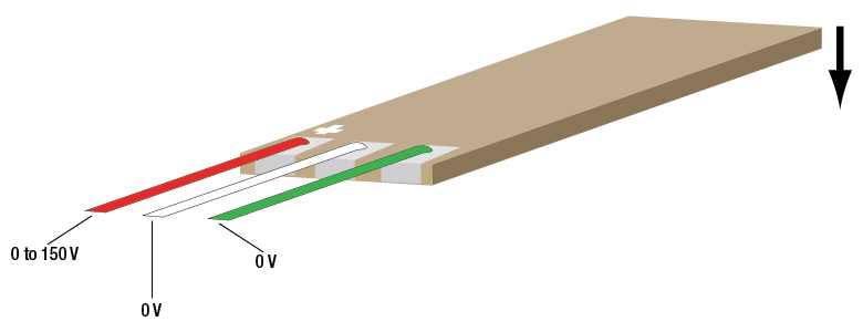
With the bimorph bender oriented so that the plus sign faces up, a positive voltage between 0 and 150 V applied to the red wire will cause top layers to elongate while the length of the bottom layers remains the same. The unfixed end of the bender flexes downwards, as shown in Figure 3a, as the applied voltage increases.
If a negative voltage between 0 and -150 V is applied to the green wire, the bottom layers elongate while the top layers do not change length. The unfixed end of the bender flexes upwards, as shown in Figure 3b.
When using single-side voltage control, never vary the voltage on both the red and green lead at the same time, as a voltage difference of more than 150 V between these two leads will damage the actuator.
Differential Voltage Control
Differential Voltage Control is useful for cases where the bending actuator needs to flex in both directions. Applying a varying voltage to the center white wire, while applying constant voltages to the green and red wires, allows the operator to control how much the top layers elongate with respect to the bottom layers. This controls the direction and magnitude of the displacement.
Differential voltage contol of the piezo bender can be performed by configuring the device as described by Option 3 or Option 4 in the table. For both driving configurations, a 150 V voltage difference is established between the red and the green wire and the maximum displacement is reached. In the case of Option 3, this is accomplished by holding the red wire at 150 V and the green wire at 0 V, while the voltage on the white wire is varied between 0 and 150 V. In the case of Option 4, the red wire is held at 75 V and the green wire at -75 V, while the voltage on the white wire is varied from -75 to 75 V.
For example, if the PB4NB2W piezo bender actuator is configured according to Option 3 and the voltage applied to the white wire is 75 V, the magnitude of the voltage applied across the top and bottom layers is the same: the elongation of the top and bottom layers are the same and there is no displacement of the tip. When 0 V is applied to the white wire, the top layer elongates, the length of the bottom layer does not change, and displacement is 450 µm downwards. When 150 V is applied to the white wire, the bottom layer elongates, the length of the top layer does not change, and displacement is 450 µm upwards. For intermediate voltages applied to the white wire, the top and bottom layers elongate to different lengths and the magnitude and direction of the displacement varies accordingly.
Long Term Operation
These piezoelectric bimorph bending actuators were tested for long term durability at room temperature (25 °C) and an ambient humidity of 45%; at frequencies at or below 100 Hz, the actuators were still functional after 1 x 10⁸ cycles.
Cleaning for Vacuum Compatibility
When suitable for vacuum applications, Thorlabs' piezo chips have the rated vacuum compatibility specified in their Info Icons (![]() ). While no extra cleaning is needed to achieve this value, we recommend cleaning these products with isopropyl alcohol (IPA) in an ultrasonic immersion tank and then baking them at 60 °C for two hours. Do not immerse the device in other organic solvents.
). While no extra cleaning is needed to achieve this value, we recommend cleaning these products with isopropyl alcohol (IPA) in an ultrasonic immersion tank and then baking them at 60 °C for two hours. Do not immerse the device in other organic solvents.
| Posted Comments: | |
Luis Cobar
(posted 2023-12-15 12:56:38.27) Hi, I was wondering if you could provide the estimates of how long does it takes for the PB4NB2S to move when applied a voltage? Also, what factors may affect the timing for movement of the piezo? ksosnowski
(posted 2023-12-18 02:10:05.0) Hello Luis, thanks for reaching out to Thorlabs. Piezo elements act like capacitors and must be charged by the driver's current output. The driver used and it's max slew rate can potentially limit the speed at which you can change the voltage across the piezo which results in displacement. The page for our MDT693B piezo driver has a bandwidth tutorial with some examples. These piezo benders also have a low resonant frequency, and adding mass to the bender with further drop the resonance. We have heating data as a function of frequency on our website however we recommend remaining below 1/3 the resonant frequency to avoid heating. These are based on soft PZT material and not intended for resonant operation like hard PZTs. I have reached out to discuss this application further. user
(posted 2023-07-07 16:48:48.65) I would like to know the capacity of all piezoelectric benders. cdolbashian
(posted 2023-07-14 04:15:14.0) Thank you for contacting Thorlabs! For PB4VB2W and PB4VB2S, the capacitance is 145 nF ± 15% for each side of the bimorph. For PB4NB2W and PB4NB2S, the capacitance is 550 nF ± 15% for each side of the bimorph. The capacitance spec is listed in the product specsheet. ガントゥムル フルレー
(posted 2023-01-04 12:28:43.35) I would like to know the Young's modulus and piezoelectric constant of PB4NB2W. Thank you. cdolbashian
(posted 2023-01-10 02:41:18.0) Thank you for reaching out to us with this inquiry. The Young’s modulus of the ceramic material in this device is about 67GPa. The piezo constants, d33 and d31, are ~710 pC/N and ~(-320) pC/N respectively. ガントゥムル フルレー
(posted 2022-12-27 11:41:45.163) PB4NB2Wのヤング率と圧電定数を知りたいです。宜しくお願い致します。 Mickey London
(posted 2022-04-18 05:35:19.057) I have two of those. I am driving them with BD150 by piezodrive.com at low frequencies 1-25Hz.
They make quite strong audible noise which I cannot cancel. It is quite frustrating because I was using other piezo benders from other companies before and they did not do that.
Thank you
Mickey cdolbashian
(posted 2022-04-20 04:52:27.0) Thank you for contacting Thorlabs. Due to the high resonance of our bender benefiting from the monolithic design, harmonics from driving signals like square and triangle wave could resonate with the bender and causing audible noises. Sine wave would be much better in this case. Another thing worth checking is that if the holder is tightly fastened. We will get in touch with you via email to help troubleshoot further. Saravanakumar Dharmaraj
(posted 2022-02-24 20:05:01.943) Is possible to actuate one side of the bimorph and use the other to sense? cdolbashian
(posted 2022-02-28 10:55:33.0) Thank you for contacting Thorlabs with this inquiry Saravanakumar. We have confirmed this application ourselves thanks to your suggestion here. Francisco Moreno
(posted 2021-02-03 13:01:40.343) Hello i hope that you have a nice day. I would like know if you help me with the next information: i would like know the measurements and the differents angles of displacements about the actuator PB4NB2S when the the voltage is different o varying
i don't know if you have this kind information, by the way, this information is necessary for me because I am using this device for my thesis YLohia
(posted 2021-02-05 09:33:32.0) Hallo, thank you for contacting Thorlabs and for choosing our products for your thesis. We currently do not have a proper way to directly measure the angular displacements as they are too small. The angles can be estimated by arctan(Displacement / Free Length), where the Free Length of the PB4NB2S is 28mm. Francisco Moreno
(posted 2020-09-28 20:56:44.01) Hello, I would like to know if you could help me with any information about the piezoelectric bender PB4NB2S, i need information about the material of the layers of the devices, young´s modulus, d ensity of piezoelectric material, piezoelectric constant, Relative permittivity of piezoelectric material, Total capacitance of piezoelectric material
This information is importan for me, because i am using the piezolectric devices for my PHD thesis
I hope that you can help me, thank you for your attention YLohia
(posted 2020-10-01 03:38:00.0) Hello, thank you for contacting Thorlabs and for choosing our products for your Ph.D thesis. We have reached out to you directly via email to discuss the information that you requested. Xie Caijin
(posted 2020-07-17 15:01:13.14) 您好,我们想咨询一下将压电双晶片末端切掉数毫米是否影响压电双晶片的起振。 YLohia
(posted 2020-07-17 10:29:53.0) Hello, thank you for contacting Thorlabs. An applications engineer from our team in China will contact you directly. Alternately, our team can be contacted at techsupport-cn@thorlabs.com. 才津 谢
(posted 2020-07-16 10:16:43.007) 如果我们将压电双晶片的末端切掉几毫米,压电双晶片是否还能正常起振 YLohia
(posted 2020-07-16 10:34:34.0) Hello, thank you for contacting Thorlabs. An applications engineer from our team in China will contact you directly. Francisco Moreno
(posted 2020-04-30 23:54:37.103) Hello I have a question about the piezoelectric device, i would like know what kind of material is this device (PZT, PbTiO3)?? YLohia
(posted 2020-05-06 08:55:29.0) Hello, thank you for contacting Thorlabs. The PB4NB2W is constructed from multiple co-fired piezoceramic layers made of PZT and Pb(Zr,Ti)O3. Ag/Pd are used between these ceramic layers. Xie Caijin
(posted 2020-01-03 12:09:18.18) I want to ask that, which method do you use to get the resonant frequency and displacement of the bimorph.
Thank you. nbayconich
(posted 2020-01-07 02:30:56.0) Thank you for contacting Thorlabs. To measure the resonant frequency, we pre-attached the bimorph to a holder and connect an impedance analyzer between the white and green wire connections or red and green wires.
To test the displacement of the bimorph, an laser source and a position sensor is used to record how much the beam is shifted. We will reach out to you directly with more details. Francisco Moreno
(posted 2019-06-04 10:16:40.6) Hello, I have two questions, the first is:
What is the minimun range or displacement
This kind of devices is compatible with clean room and cells ???
this last question due to I would like move cell with this devices
Thank for your attention and I hope your soon answer YLohia
(posted 2019-06-13 08:51:30.0) Hello, thank you for contacting Thorlabs. The minimum displacement (or resolution) of a piezo device is determined by the minimum voltage step (or noise) of the control voltage source. We reached out to you directly to gather more information about your clean room application. |

 Zoom
Zoom| Item #a | Info | Displacement | Free Lengthb | Dimensions | Resonant Frequency (No Load) |
Blocking Force |
Pre-Attached Holder |
|---|---|---|---|---|---|---|---|
| PB4VB2W | ±135 µm ± 15% | 16 mm | 20.0 mm x 8.0 mm x 0.8 mmc | 930 Hz | 1.4 N (0.31 lbs) |
No | |
| PB4VB2S | 27.0 mm x 19.0 mm x 3.0 mmc,d | Yes | |||||
| PB4NB2W | ±450 µm ± 15% | 28 mm | 32.0 mm x 7.8 mm x 0.8 mmc | 370 Hz | 1.5 N (0.33 lbs) |
No | |
| PB4NB2S | 39.0 mm x 19.0 mm x 3.0 mmc,d | Yes |
- For complete specifications, please see the Info Icons (
 ) above.
 - This is measured from the edge of the piezo without the electrodes towards the silver plus sign.
- Does Not Include Wires
- Includes Holder with Ø4.3 mm Mounting Through Holes