 Products Home / Actuators, Adjusters, & Transducers / Piezoelectric Chips and Stacks / Piezoelectric Actuators with Attached Strain Gauges
Piezoelectric Actuators with Attached Strain Gauges
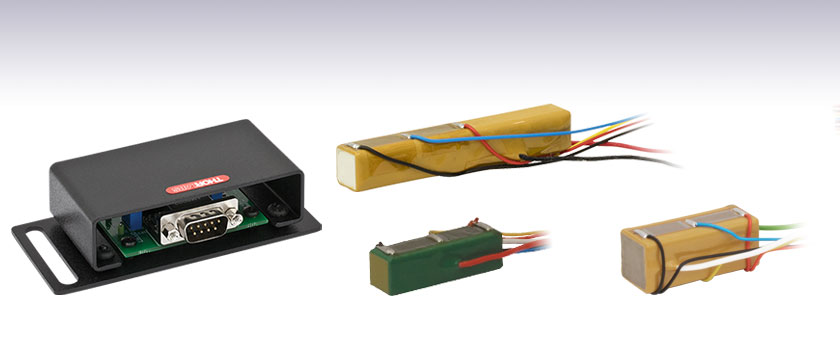
- Co-Fired and Discrete Stack Options
- Strain Gauges Attached to Actuators in Wheatstone Bridge Circuit Configuration
- Pre-Amplification Circuit Available for Use with Strain Gauge Reader
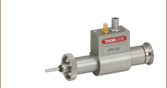
PZS001
Co-Fired Piezo Actuator, 17.4 µm Stroke
6.0 mm x 7.0 mm x 20.0 mm
AMP002
Strain Gauge Pre-Amp Circuit
PK4FYC2
Discrete Stack Piezo Actuator, 38.5 µm Stroke
7.3 mm x 7.3 mm x 36.0 mm
PC4GRC2
Co-Fired Piezo Actuator, 21.0 µm Stroke
8.5 mm x 9.5 mm x 20.0 mm


Please Wait
| Piezo Selection Guide |
|---|
| Piezoelectric Ceramic Stacks |
| Discrete, Square |
| Discrete, Square with Through Hole |
| Discrete, Round |
| Discrete, Ring |
| Discrete, Hermetically Sealed |
| Discrete, Shear (1D to 3D Positioners) |
| Co-Fired: Square, Square with Through Hole, Round, & Ring |
| Co-Fired or Discrete: Square with Strain Gauges |
| Piezoelectric Crystal Stacks |
| Square |
| Piezoelectric Chips |
| Mounted Piezoelectric Actuators |
| Ultrasonic Piezo Chips & Transducers |
| Vibrating Piezo Actuator |

Features
- Epoxy-Coated for Protection Against Rough Handling and Mechanical/Chemical Contamination
- Designed for Closed-Loop Operation
- Maximum Displacements Between 9.0 µm and 100.0 µm
- 75 V, 100 V, and 150 V Max Drive Voltages
- Strain Gauge Pre-Amp Circuit Compatible with KSG101 Reader
Each of our piezoelectric actuator includes four resistive strain gauges, in a Wheatstone bridge circuit configuration, bonded directly to the piezoelectric actuator. These actuators are designed to be used in a closed-loop system, in which the strain gauge signal is monitored and used to determine the piezo control drive voltage. Compared with open-loop configurations, a closed-loop configuration enables improved control over, and knowledge of, the actuator's displacement during operation. Closed-loop operation is also used to compensate for hysteresis effects.
The four foil-type strain gauges are attached to the durable epoxy resin coating that seals the actuator, and wire leads are soldered to the terminals of the strain gauge circuit. Two gauges are bonded, one next to the other, along one side of the actuator, and the other two gauges are bonded to the opposite side. In each of these pairs of gauges, one is active and one is passive. The active gauge is oriented to maximize its response to the changes in the length of the actuator. The passive gauge is oriented to minimize its response to actuator length variations; it responds primarily to changes in temperature, and its inclusion mitigates temperature-related effects on the strain measurement.
Each actuator has wire leads soldered to the positive and negative electrodes on the actuator. Co-fired piezo actuators are fabricated by interleaving lead zirconate titanate (PZT) layers and electrodes and then sintering the entire structure into a monolithic unit. Discrete-stack piezo actuators are constructed by bonding multiple, individually-sintered, piezoelectric chips together using epoxy and glass beads. Additional differences between the two designs include conductor and insulation details. Please see the Operation tab for more Information.
Thorlabs recommends using the KSG101 Strain Gauge Reader and the AMP002 Pre-Amplification Circuit, sold below, with these piezoelectric actuators.
Integration
For connecting loads to the PZS001 Actuator, we recommend using a room-temperature epoxy, such as Thorlabs' F120 Epoxy. To mount all other available piezo stacks, we recommend using an epoxy that cures at a temperature lower than 80 °C (176 °F), such as our 353NDPK or TS10 Epoxies or Loctite® Hysol® 9340. When interfacing a mechanical load with the piezoelectric actuator, it is important to center the mechanical load on the actuator's end face to avoid applying a torque. If the actuator is incorporated into a design that calls for a preload, it is recommended that the preload does not exceed 50% of the specified blocking force. Please refer to the Operation tab above for more information.
For the discrete stack actuators and the PZS001 co-fired actuator, the red lead must be connected to the high side of the voltage source used to drive the actuator; for all of the other co-fired actuators below, the green lead must be connected to the high side of the voltage source. Do not drive the piezoelectric actuator with a reverse bias voltage, as this could destroy the device. Piezoelectric actuators should not be used in liquid, in the presence of combustible gasses or liquids, or cleaned with organic solvents.
Discrete Piezoelectric Stack Actuators with Strain Gauges
| Item # | PK2FMC2a | PK3HUC2a | PK4FYC2a | PK4GA7C2a |
|---|---|---|---|---|
| Performance | ||||
| Maximum Drive Voltage | 75 V | 100 V | 150 V | 150 V |
| Displacement at Maximum Drive Voltage | 11.2 µm ± 15%b | 32.0 µm ± 15%b | 38.5 µm ± 15%b | 100.0 µm ± 15%b |
| Recommended Drive Voltage Limit for Continuous Operation |
75 V | 100 V | 150 V | 150 V |
| Displacement During Continuous Operationc |
11.2 µm ± 15% | 32.0 µm ± 15% | 38.5 µm ± 15% | 100.0 µm ± 15% |
| Hysteresis | <15% | <15% | <15% | <15% |
| Load for Maximum Displacementd | 400 N (90 lbs) | 1600 N (360 lbs) | 400 N (90 lbs) | 785 N (176 lbs) |
| Blocking Force at Maximum Drive Voltage | 1000 N (225 lbs) | 4000 N (899 lbs) | 1000 N (225 lbs) | 1960 N (441 lbs) |
| Resonant Frequency (No Mechanical Load)e | 115 kHz ± 15% | 41 kHz ± 15% | 34 kHz ± 15% | 14 kHz ± 15% |
| Impedance at Resonant Frequency | 50 mΩ | 60 mΩ | 150 mΩ | 95 mΩ |
| Capacitance @ 1 kHz, 1 VRMS | 4.2 µF ± 15% | 21.0 µF ± 15% | 3.5 µF ± 15% | 16.0 µF ± 15% |
| Dissipation Factor | <2.0%f | <2.0%f | <2.0% | <2.0%f |
| Performance Graphs (Click Icon to View Graphs) |
||||
| Anti-Resonant Frequencyg | 150 kHz ± 15% (No Load) | 54 kHz ± 15% (No Load) | 42 kHz ± 15% (No Load) | 17 kHz ± 15% (No Load) |
| Recommended Preload | <400 N (90 lbs) | <1600 N (360 lbs) | <400 N (90 lbs) | <785 N (176 lbs) |
| Lifetime | >1x10⁹ Cyclesh | >1x10⁹ Cyclesi | >1x10⁹ Cyclesj | >1x10⁹ Cyclesk |
| Strain Gauge Circuit | ||||
| Bridge Arm Resistance | 350 Ω ± 0.3% | 350 Ω ± 0.3% | 350 Ω ± 0.3% | 350 Ω ± 0.3% |
| Gauge Factor | 2 | |||
| Excitation Voltage (Recommended Max) | 4.5 Vrms | |||
| Physical | ||||
| Actuator End Face Area | 5.0 mm x 5.0 mm (0.20" x 0.20") |
10.0 mm x 10.0 mm (0.39" x 0.39") |
5.0 mm x 5.0 mm (0.20" x 0.20") |
7.0 mm x 7.0 mm (0.28" x 0.28") |
| Length Along Actuating Axis | 10.5 mm (0.41") | 30.0 mm (1.18") | 36.0 mm (1.42") | 90.0 mm (3.54") |
| Length Tolerance | ±5 µm | ±5 µm | ± 100 µm | ±5 µm |
| Maximum Dimensions | 7.5 mm x 6.5 mm x 10.5 mm (0.30" x 0.26" x 0.41") |
12.5 mm x 11.5 mm x 30.0 mm (0.49" x 0.45" x 1.18") |
7.3 mm x 7.3 mm x 36.0 mm (0.30" x 0.26" x 1.42") |
9.5 mm x 8.5 mm x 90.0 mm (0.37" x 0.33" x 3.54") |
| Operating Temperature | -25 to 65 °C | |||
| Curie Temperature | 230 °C | |||
Co-Fired Piezoelectric Stack Actuators with Strain Guages
| Item # | PC4QMC2a | PC4WMC2a | PZS001 | PC4QQC2a | PC4GQC2a | PC4GRC2a |
|---|---|---|---|---|---|---|
| Performance | ||||||
| Maximum Drive Voltage | 150 V | 150 V | 150 Vb | 150 V | 150 V | 150 V |
| Displacement at Maximum Drive Voltage |
9.0 µm ± 15%c | 10.0 µm ± 15%c | 17.4 ± 2.0 μm (±11%) | 19.0 µm ± 11%c | 19.0 µm ± 11%c | 21.0 µm ± 11%c |
| Recommended Drive Voltage Limit for Continuous Operation |
150 V | 150 V | 100 V | 150 V | 150 V | 150 V |
| Displacement During Continuous Operationd |
9.0 µm ± 15% | 10.0 µm ± 15% | 11.6 ± 2.0 µm (±17%) | 19.0 µm ± 11% | 19.0 µm ± 11% | 21.0 µm ± 11% |
| Hysteresis | ≤15% | ≤15% | Not Specified | ≤15% | ≤15% | ≤15% |
| Load for Maximum Displacemente | 400 N (90 lbs) | 100 N (22.5 lbs) | Not Specified | 400 N (90 lbs) | 800 N (180 lbs) | 800 N (180 lbs) |
| Blocking Force | 1000 N (225 lbs) at 150 V | 250 N (55 lbs) at 150 V | 850 N (191 lbs) | 1000 N (225 lbs) at 150 V | 2000 N (450 lbs) at 150 V | 2000 N (450 lbs) at 150 V |
| Resonant Frequency (No Mechanical Load)f |
115 kHz ± 10% | 115 kHz ± 10% | 69 kHz | 65 kHz ± 10% | 64 kHz ± 10% | 59 kHz ± 10% |
| Impedance at Resonant Frequency | 300 mΩ | 700 mΩ | Not Specified | 200 mΩ | 200 mΩ | 200 mΩ |
| Capacitance @ 1 kHz, 1 VRMS | 650 nF ± 15% | 180 nF ± 15% | 1.40 µF ± 20% | 1.35 µF ± 15% | 2.5 µF ± 15% | 2.8 µF ± 15% |
| Dissipation Factor | <2.0%g | <2.0%g | Not Specified | <2.0%g | <2.0%g | <2.0%g |
| Performance Graphs (Click Icon to View Graphs) |
N/A | |||||
| Anti-Resonant Frequencyh | 170 kHz ± 10% (No Load) |
165 kHz ± 10% (No Load) |
Not Specified | 95 kHz ± 10% (No Load) |
95 kHz ± 10% (No Load) |
85 kHz ± 10% (No Load) |
| Preload | <400 N (90 lbs) Recommended | <100 N (22.5 lbs) Recommended |
425 N (95.5 lbs) Maximum |
<400 N (90 lbs) Recommended | <800 N (180 lbs) Recommended | <800 N (180 lbs) Recommended |
| Lifetime | 1x10⁹ Cyclesi | 1x10⁹ Cyclesi | 1x10⁹ Cyclesi | 1x10⁹ Cyclesi | 1x10⁹ Cyclesi | 1x10⁹ Cyclesi |
| Strain Gauge Circuit | ||||||
| Bridge Arm Resistance | 350 Ω ± 0.3% | 350 Ω ± 0.3% | 350 Ω | 350 Ω ± 0.3% | 350 Ω ± 0.3% | 350 Ω ± 0.3% |
| Gauge Factor | 2 | |||||
| Excitation Voltage (Recommended Max) |
4.5 Vrms | |||||
| Physical | ||||||
| Actuator End Face Area | 5.0 mm x 5.0 mm (0.20" x 0.20") |
3.0 mm x 2.0 mm (0.12" x 0.08") |
5.0 mm x 5.0 mm (0.20" x 0.20") |
5.0 mm x 5.0 mm (0.20" x 0.20") |
7.0 mm x 7.0 mm (0.28" x 0.28") |
7.0 mm x 7.0 mm (0.28" x 0.28") |
| Length Along Actuating Axis | 10.0 mm (0.39") | 10.0 mm (0.39") | 20.0 mm (0.79") | 18.0 mm (0.71") | 18.0 mm (0.71") | 20.0 mm (0.78") |
| Length Tolerance | ±5 µm | ±5 µm | ±100 µm | ±5 µm | ±5 µm | ±5 µm |
| Maximum Dimensions | 7.2 mm x 6.5 mm x 10.0 mm (0.29" x 0.26" x 0.39") |
4.5 mm x 5.0 mm x 10.0 mm (0.18" x 0.20" x 0.39") |
7.0 mm x 6.0 mm x 20.0 mm (0.28" x 0.24" x 0.79") |
6.5 mm x 6.5 mm x 18.0 mm (0.26" x 0.26" x 0.71") |
9.5 mm x 8.5 mm x 18.0 mm (0.37" x 0.33" x 0.71") |
9.5 mm x 8.5 mm x 20.0 mm (0.37" x 0.33" x 0.78") |
| Operating Temperature | -25 to 65 °C | -25 to 65 °C | -25 to 85 °C | -25 to 65 °C | -25 to 65 °C | -25 to 65 °C |
| Curie Temperature | 230 °C | 230 °C | N/A | 230 °C | 230 °C | 230 °C |
AMP002 Pin Connections
D-type Male
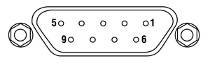
| Pin | Function |
|---|---|
| 1 | Oscillator Input |
| 2 | + 15 V Input Supply |
| 3 | - 15 V Input Supply |
| 4 | 0 V Supply |
| 5 | Amplifier Output |
| 6 | 0 V Supply |
| 7 | ID Resistor Connection |
| 8-9 | N/C |
Operation Notes
Click to Enlarge
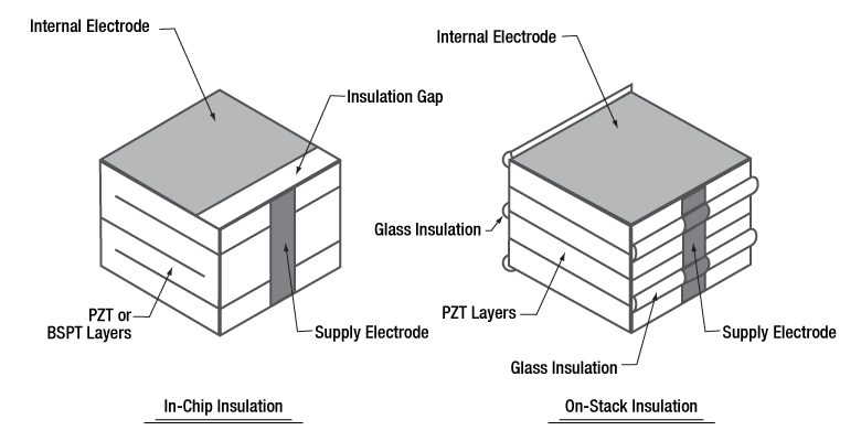
Figure 1: Diagram of Piezo Stack Insulation Methods:
(a) In-Chip Insulation Used in Standard Chips and Discrete Stacks,
(b) On-Stack Insulation Used in Co-Fired Stacks
Click to Enlarge
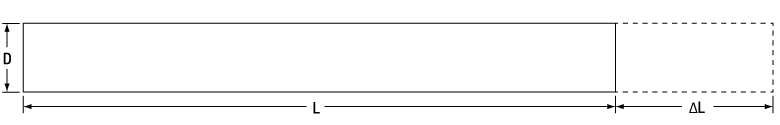
Figure 2: A rod at rest has length L, and strain extends its length by ΔL.

Click to Enlarge
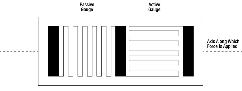
Figure 3: The conductor of a metal foil strain gauge is routed between electrical contat pads in a grid pattern. Force applied along the indicated axis provides maximum response.
Click to Enlarge
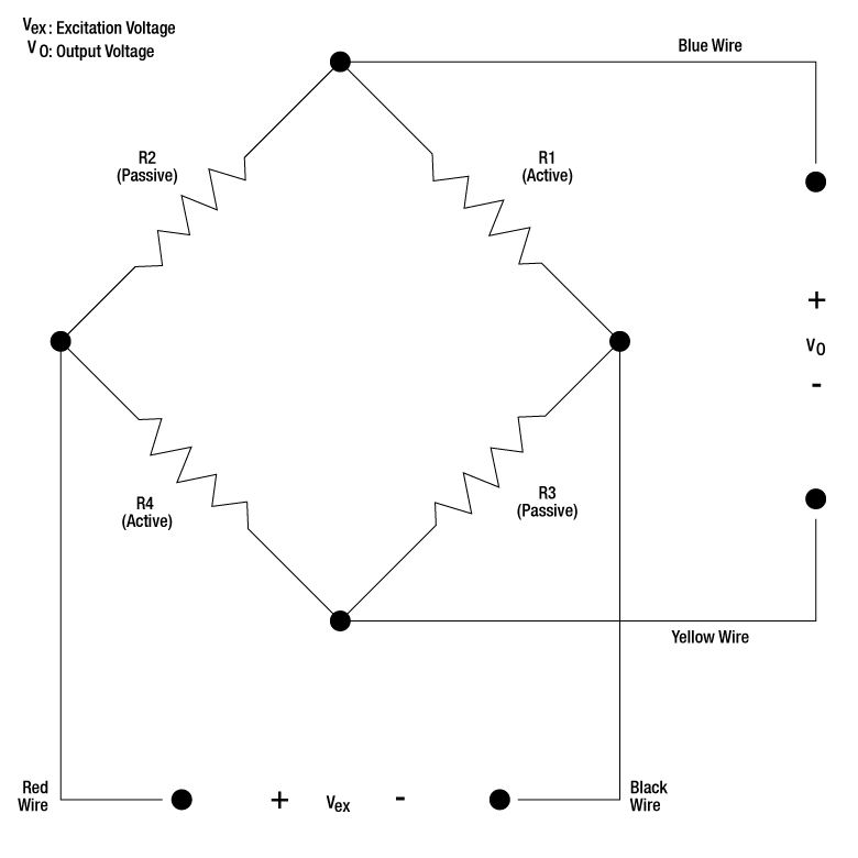
Figure 4: The four strain gauges attached to the piezoelectric actuators are arranged in a Wheatstone bridge circuit with two active and two passive resistance arms. The passive arms minimize the contribution of temperature changes to the strain measurement. The wire colors above correspond to the PK4FYC2, PC4QMC2, PC4QQC2, PC4GQC2, and PC4GRC2 Actuators. (The -Vex wire is white on the PZS001 Actuator.)
Click to Enlarge
Figure 5: In each strain gauge pair, one is active and one is passive. The active gauge is oriented for maximal response to force applied along the indicated axis. The passive gauge has an orthogonal orientation.
Co-Fired Piezo Chips, Co-Fired Piezo Stacks, and Discrete Piezo Stacks
Generally speaking, Thorlabs' co-fired piezo chips and stacks are constructed similarly. In both cases, a structure is built up from alternating electrode layers and green-state lead zirconate titanate (PZT) piezoelectric layers. (The co-fired piezo chips are also available with BiScO3-PbTiO3 (BSPT) piezoelectric layers for higher temperature applications.) The assembled structure is then sintered into a single monolithic unit. Supply electrodes of opposite polarity are attached to opposite sides of the structure. Each internal electrode is electrically coupled to one or the other supply electrode, such that no two adjacent internal electrodes have the same polarity. The most significant differences between the co-fired chips and stacks arise from the way each internal electrode is electrically isolated from the supply electrodes of opposite polarity. The different electrical insulation approaches influence the mechanical properties of the actuators. Actuators fabricated using the two different approaches are diagrammed in Figure 1.
In the case of the chips (In-Chip Insulation), the internal electrodes of opposite polarities alternate. Each internal electrode layer is shorter than the full width of the piezo layer. All electrodes of one polarity have edges that are flush with one side of the chip, and all electrodes with the opposite polarity are flush with the opposite side of the chip. Because the electrode does not extend all the way to the opposite edge, the far end of the electrode is completely surrounded by PZT and BSPT material. The PZT and BSPT material enclosing the end of the electrode is insulating, which electrically isolates this electrode from the supply electrode of opposite polarity. This approach to electrically insulating the electrodes creates a region of stress at the edge of the electrode. The stress arises both due the abrupt change in thickness on either side of the electrode edge, as well as the tensile stress created when the PZT and BSPT material sandwiched between electrodes responds to an applied voltage drive signal, but the insulating PZT and BSPT material beyond the edge of the electrodes does not. This stress limits the maximum height of chips manufactured using this approach. The height of chips are limited to ensure internal stresses are low and do not affect lifetime or performance. Chips are sealed in a ceramic layer that offers superior resistance to humidity and heat than epoxy resin coatings.
One way of increasing the height, and therefore the maximum stroke, of piezo actuators based on these chips is to fabricate discrete piezo stacks. These are manufactured by bonding multiple chips together in series using a glass-bead epoxy. Discrete stacks can be fabricated to substantially longer lengths than co-fired chips or stacks, and this allows them to achieve higher maximum displacements while maintaining sub-millisecond response times and a low drive voltage range. As the constituent chips are sealed within a ceramic barrier layer, discrete stacks have superior resistance to humidity and heat than co-fired stacks, which are sealed in an epoxy resin coating.
In the case of co-fired stacks (On-Stack Insulation), the electrodes extend across the full width of the PZT layers. The edges of the electrodes are flush with all four sides of the stack, including the side with the supply electrode of opposite polarity. The edge of the internal electrode is insulated from that supply electrode by a layer of glass filament applied to the side of the stack. Precision localized application of the glass filament ensures that the electrode edge is electrically isolated from the supply electrode, and that the filament is applied over minimal surface area; the ability of the supply electrode to make electrical connections to the desired internal electrodes is not affected, and the small amount of applied glass filament does not affect the operation of the actuator. With their full-width electrodes, piezo actuators made using this insulating approach are characterized by homogeneous internal stress. Co-fired stacks can therefore be fabricated with greater heights than chips fabricated using the in-chip insulation approach. Co-fired stacks also have a higher percentage of active PZT material than the discrete stacks, which include inactive bonding layers of glass-bead epoxy. They are coated in an epoxy resin.
Making Measurements of Strain Using the Attached Strain Sensor
Strain, ε, is the measure of the deformation of a body due to an applied force, and it is defined as a fractional change in length, L. Referencing Figure 2,

Metal foil strain gauges are frequently chosen to measure small magnitudes of strain, which is expressed in terms of microstrain (µε). Foil gauges are attached to test objects during use. Strain experienced by the object is directly transferred to the strain gauge, resulting in the gauge expanding and contracting with the object. As the electrical resistance of a foil strain gauge varies linearly with the length of its conducting element, monitoring the resistance of the strain gauge provides a means of determining strain. The grid pattern of the conductor, shown in Figure 3, results in maximal deformation of the conductor when tensile or compressive forces are applied along the indicated axis. Orthogonally applied forces have minimal effect on the conductor's dimensions, or the electrical resistance.
Four foil gauges arranged in a Wheatstone bridge circuit configuration, shown in Figure 4, are commonly used to measure small changes in resistance. Each of the four gauges in this voltage divider circuit functions as a separate resistive arm in the Wheatstone bridge. The circuit is operated by applying an excitation voltage, Vex, and measuring the output voltage, Vo, as indicated; the output voltage changes as the resistances in the four arms vary with applied strain.
In the case of our piezoelectric actuators, two of the four gauges are bonded, in an adjacent configuration, to one side of the actuator. The other two gauges are similarly bonded to the opposite side of the actuator. One gauge in each pair is oriented so that its active gauge length is aligned with the direction of actuation, and the other is oriented orthogonally, as is diagrammed in Figure 5. The active gauge is the one oriented to respond maximally to changes in the length of the actuator. The other, passive, gauge responds minimally to changes in the length of the actuator; its resistance changes primarily in response to changes in temperature. Both temperature and strain affect the resistance of metal foil gauges, and the inclusion of passive gauges in the circuit is one method used to minimize the effects of temperature changes on the strain measurement.
The sensitivity of the strain gauge, defined as the ratio of the fractional change in electrical resistance, R, to the fractional change in length, is called the gauge factor:

The gauge factor for all of our piezoelectric actuators is 2.
Strain is calculated using the gain factor, excitation voltage, and measured output voltage:

For convenience, wires are attached to the strain gauges' solder tabs during fabrication of our piezoelectric actuators. These wires have a gauge of 0.5 mm and are color-coded to identify their function: the red wire is connected to +Vex, the black wire to -Vex (the -Vex wire is white on the PZS001 Actuator), the blue wire to +Vo, and the yellow wire to -Vo.
We recommend using the AMP002 pre-amplification circuit, to amplify the strain sensor signal from the piezoelectric actuators before sending it to a strain gauge reader, such as the KSG101 Reader. When metal foil gauges are used to measure small changes in strain, it is typical to amplify the sensor signal prior to measuring it.
For additional information describing how metal foil strain gauges are used to measure the strain in the piezoelectric actuators, please see our Strain Gauge Tutorial.
Power Connections
A positive bias should be applied across the device using the wires connected to the electrodes. The positive wire should receive positive bias, and the other wire should be connected to ground. Applying a negative bias across the device may cause mechanical failure. The positive wire is red or green, while the ground wire is black or white.
Interfacing a Piezoelectric Stack with a Load
Piezoceramics are brittle and have low tensile strength. Avoid loading conditions that subject the actuator to lateral, transverse, or bending forces. When applied incorrectly, an external load that may appear to be compressive can, through bending moments, cause high tensile stresses within the piezoelectric device. Improperly mounting a load to the piezoelectric actuator can easily result in internal stresses that will damage the actuator. To avoid this, the piezoelectric actuator should be interfaced with an external load such that the induced force is directed along the actuator's axis of displacement. The load should be centered on and applied uniformly over as much of the actuator's mounting surface as possible. When interfacing the flat surface of a load with an actuator capped with a flat mounting surface, ensure the two surfaces are highly flat and smooth and that there is good parallelism between the two when they are mated. If the external load is directed at an angle to the actuator's axis of displacement, use an actuator fitted with a hemispherical end plate or a flexure joint to achieve safe loading of the piezoelectric stack.
To attach a load to one of our AE series piezo stacks, we recommend using a room-temperature epoxy, such as Thorlabs' F120 Epoxy. For connecting loads to our PC4FL piezo stack, we recommend using an epoxy that cures at a temperature lower than 80 °C (176 °F), such as our 353NDPK or TS10 Epoxies or Loctite® Hysol® 9340. Loads should be mounted only to the translating, uncoated faces of the piezoelectric stack; the coated sides of our co-fired piezo stacks do not translate, and mounting a load to a non-translating face may lead to the mechanical failure of the actuator. Our PC4FL Piezo Stack is compatible with the following accessories to minimize internal stress: our PKFESP Ø5 mm Ceramic End Hemispheres (set of 25) and PKFCUP Conical End Cups (set of 10). Some correct and incorrect approaches to interfacing loads with piezoelectric stacks fitted with end plates are discussed in the following.
Click to Enlarge
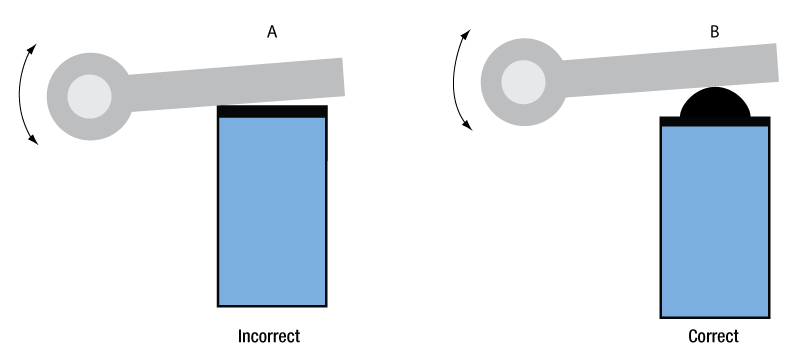
Figure 6: Actuation of a lever arm using stack fitted with a flat plate (A, Incorrect), and a hemispherical plate (B, Correct).
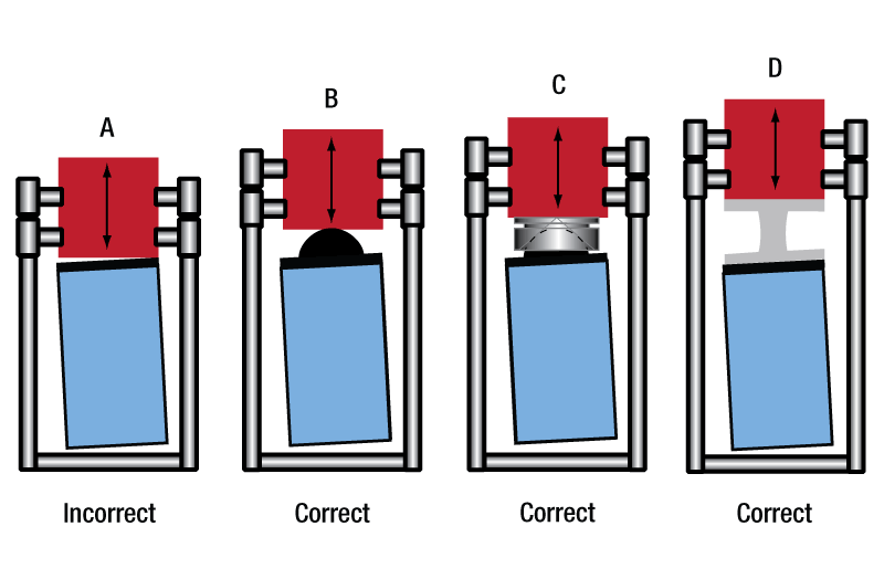
Click to Enlarge
Figure 7: Loads properly and improperly mounted to PZT actuators using a variety of interfacing methods.
The image at left presents incorrect (A, far-left) and correct (B, near-left) methods for using a piezoelectric stack to actuate a lever arm. The correct method uses a hemispherical end plate so that, regardless of the angle of the lever arm, the force exerted is always directed along the translational axis of the actuator. The incorrect interfacing of the stack and the lever arm, shown at far-left, endangers the stack by applying the full force of the load to one edge of the stack. This uneven loading causes dangerous stresses in the actuator, including a bending moment around the base.
The image at right shows one incorrect (near-right, A) and three correct approaches for interfacing a flat-bottomed, off-axis load with a piezoelectric stack. Approaches A and B are similar to the incorrect and correct approaches, respectively, shown in the image at left. Correct approach C shows a conical end cup, such as the PKFCUP, Conical End Cups acting as an interface. The flat surface is affixed to the mating surface of the load, and the concave surface fits over the hemispherical dome of the end plate. In the case of correct approach D, a flexure mount acts as an interface between the off-axis flat mounting surface of the load and the flat mounting plate of the actuator. The flexure mount ensures that the load is both uniformly distributed over the surface plate of the actuator and that the loading force is directed along the translational axis of the actuator.
Operating Under High-Frequency Dynamic Conditions
It may be necessary to implement an external temperature-control system to cool the device when it is operated at high frequencies. High-frequency operation causes the internal temperature of the piezoelectric device to rise. The dependence of the device temperature on the drive voltage frequency for select products can be found in the Spec Sheet accessed by clicking the red Docs icon (![]() ) below. The temperature of the device should not be allowed to exceed its specified maximum operating temperature.
) below. The temperature of the device should not be allowed to exceed its specified maximum operating temperature.
Estimating the Resonant Frequency for a Given Applied Load
A parameter of significance to many applications is the rate at which the piezoelectric actuator changes its length. This dimensional rate of change depends on a number of factors, including the bandwidth of the piezoelectric actuator (its resonant frequency), the absolute maximum bandwidth of the driver (its slew rate), the maximum current the piezoelectric device can produce, the capacitance of the piezoelectric stack, and the amplitude of the driving signal. The length of the voltage-induced extension is a function of the amplitude of the applied voltage driving the actuator and the length of the piezoelectric stack. The higher the capacitance, the slower the dimensional change of the actuator.
Quick changes in the applied voltage result in fast dimensional changes to the piezoelectric stack. The magnitude of the applied voltage determines the nominal extension of the stack. Assuming the driving voltage signal resembles a step function, the minimum time, Tmin, required for the length of the actuator to transition between its initial and final values is approximately 1/3 the period of resonant frequency. If there is no load applied to the piezoelectric stack, its resonant frequency is ƒo and its minimum response time is:

After reaching this nominal extension, there will follow a damped oscillation in the length of the actuator around this position. Controls can be implemented to mitigate this oscillation, but doing so may slow the response of the actuator.
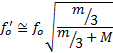
Applying a load to the actuator will reduce the resonant frequency of the piezoelectric stack. Given the unloaded resonant frequency of the actuator, the mass of the stack, m, and the mass of the load, M, the loaded resonant frequency (ƒo') may be estimated:
Piezo Driver Bandwidth Tutorial
Knowing the rate at which a piezo is capable of changing lengths is essential in many high-speed applications. The bandwidth of a piezo controller and stack can be estimated if the following is known:
- The maximum amount of current the controllers can produce. This is 0.5 A for our BPC Series Piezo Controllers, which is the driver used in the examples below.
- The load capacitance of the piezo. The higher the capacitance, the slower the system.
- The desired signal amplitude (V), which determines the length that the piezo extends.
- The absolute maximum bandwidth of the driver, which is independent of the load being driven.
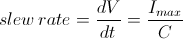
To drive the output capacitor, current is needed to charge it and to discharge it. The change in charge, dV/dt, is called the slew rate. The larger the capacitance, the more current needed:
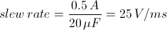
For example, if a 100 µm stack with a capacitance of 20 µF is being driven by a BPC Series piezo controller with a maximum current of 0.5 A, the slew rate is given by
Hence, for an instantaneous voltage change from 0 V to 75 V, it would take 3 ms for the output voltage to reach 75 V.
Note: For these calculations, it is assumed that the absolute maximum bandwidth of the driver is much higher than the bandwidths calculated, and thus, driver bandwidth is not a limiting factor. Also please note that these calculations only apply for open-loop systems. In closed-loop mode, the slow response of the feedback loop puts another limit on the bandwidth.
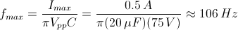
Sinusoidal Signal
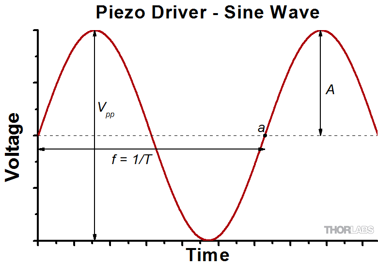
The bandwidth of the system usually refers to the system's response to a sinusoidal signal of a given amplitude. For a piezo element driven by a sinusoidal signal of peak amplitude A, peak-to-peak voltage Vpp, and frequency f, we have:
A diagram of voltage as a function of time is shown to the right. The maximum slew rate, or voltage change, is reached at t = 2nπ, (n=0, 1, 2,...) at point a in the diagram to the right:
From the first equation, above:

Thus,
For the example above, the maximum full-range (75 V) bandwidth would be
 .
.
For a smaller piezo stack with 10 times lower capacitance, the results would be 10 times better, or about 1060 Hz. Or, if the peak-to-peak signal is reduced to 7.5 V (10% max amplitude) with the 100 µm stack, again, the result would be 10 times better at about 1060 Hz.
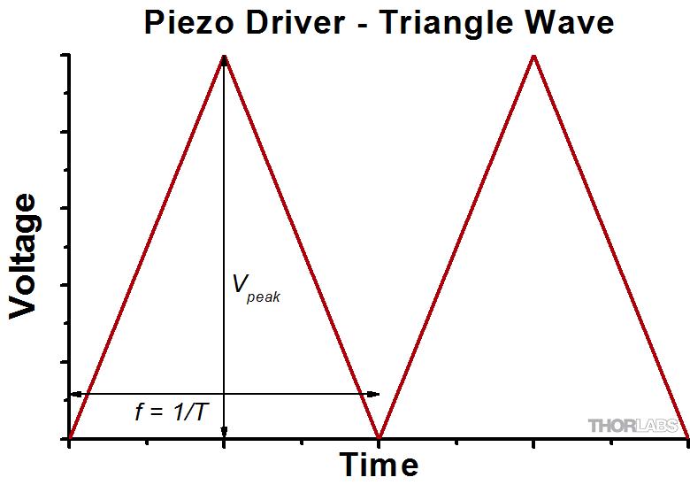
Triangle Wave Signal
For a piezo actuator driven by a triangle wave of max voltage Vpeak and minimum voltage of 0, the slew rate is equal to the slope:
![]() .
.
Or, since f = 1/T:
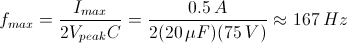
Square Wave Signal
For a piezo actuator driven by a square wave of maximum voltage Vpeak and minimum voltage 0, the slew rate limits the minimum rise and fall times. In this case, the slew rate is equal to the slope while the signal is rising or falling. If tr is the minimum rise time, then
or
 .
.
For additional information about piezo theory and operation, see the Piezoelectric Tutorials page.
| Posted Comments: | |
| No Comments Posted |

 Zoom
Zoom- Durable Epoxy Resin Coating
- Ceramic End Plates
- Maximum Displacements Between 11.2 µm and 100.0 µm
- Strain Gauge Circuit Configuration Minimizes Thermal Effects on Strain Measurement
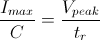
These Discrete Piezo Stack Actuators each include an attached full bridge strain gauge. The full bridge strain gauge is made by connecting four metallic foil strain gauges in a Wheatstone bridge configuration. Each individual strain gauge has a resistance of 350 Ω and a gauge factor of two. The feedback from the strain gauge can be used by a strain gauge controller to provide linear operation of the piezoelectric actuator. In order to use a strain gauge reader like the KSG101 Reader to monitor the feedback, the strain gauge must first be connected to a pre-amplification circuit like the AMP002 Pre-Amp Circuit listed below. A 3 kΩ resistor (not included) is required with the PK4FYC2 and PK3HUC2 actuators to properly interface with the AMP002 circuit. Similarly, an 18 kΩ resistor (not included) is needed to properly interface the PK4GA7C2 actuator with the AMP002 circuit. Use of the resistor is described in the AMP002 pre-amp circuit's manual. No resistor is required to interface the PK2FMC2 actuator with the AMP002 circuit.
Wires are attached to the actuator's electrodes and the electrical connections on the strain gauge circuit. The wires attached to the actuator's electrodes are larger in diameter than the wires attached to the strain gauges. The red and black strain gauge leads are used to supply the input (bridge excitation) voltage to the strain gauge. The blue and yellow strain gauge leads wires are used to monitor the output voltage of the strain gauge. For more information, please see the Operation tab.
After driving, the piezo is fully charged. Directly connecting the red and black wires has the risk of electricity discharging, spark, and even failure. We recommend using a resistor (>1 kΩ) between the red and black wires to release the charge.
| Item #a,b | Maximum Drive Voltage |
Displacement (Free Stroke)c |
Actuator End Face Area |
Actuator Length |
Resonant Frequencyd,e |
Recommended Preload |
Capacitancef | Blocking Forceg |
|---|---|---|---|---|---|---|---|---|
| PK2FMC2 | 75 V | 11.2 µm ± 15% | 5.0 mm x 5.0 mm | 10.5 mm | 115 kHz ± 15% | <400 N (90 lbs) | 4.2 µF ± 15% | 1000 N (225 lbs) |
| PK3HUC2 | 100 V | 32.0 µm ± 15% | 10.0 mm x 10.0 mm | 30.0 mm | 41 kHz ± 15% | <1600 N (360 lbs) | 21.0 µF ± 15% | 4000 N (899 lbs) |
| PK4FYC2 | 150 V | 38.5 µm ± 15% | 5.0 mm x 5.0 mm | 36.0 mm | 34 kHz ± 15% | <400 N (90 lbs) | 3.5 µF ± 15% | 1000 N (225 lbs) |
| PK4GA7C2 | 150 V | 100.0 µm ± 15% | 7.0 mm x 7.0 mm | 90.0 mm | 14 kHz ± 15% | <785 N (176 lbs) | 16.0 µF ± 15% | 1960 N (441 lbs) |

 Zoom
Zoom- Durable Epoxy Resin Coating
- Maximum Displacements Between 9.0 and 21.0 µm
- Strain Gauge Configuration Minimizes Thermal Effects on Strain Measurement
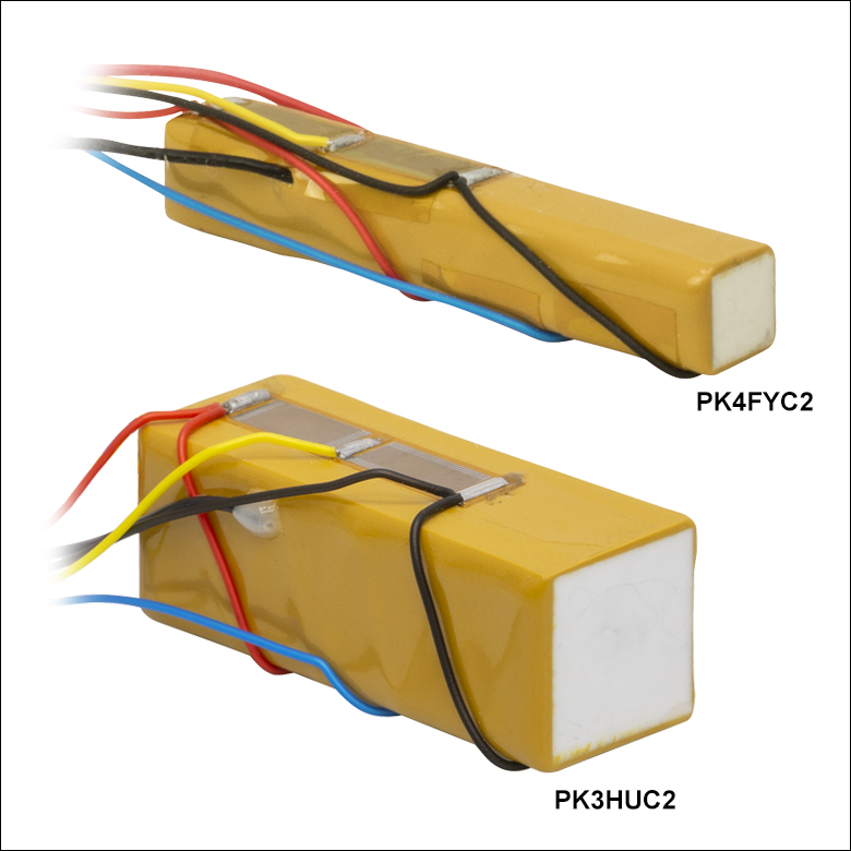
These Co-Fired Actuators each include an attached full bridge strain gauge. The full bridge strain gauge is made by connecting four metallic foil strain gauges in a Wheatstone bridge configuration. Each individual strain gauge has a resistance of 350 Ω and a gauge factor of two. The feedback from the strain gauge can be used by a strain gauge controller to provide linear operation of the piezoelectric actuator. In order to use a strain gauge reader like the KSG101 Reader to monitor the feedback, the strain gauge must first be connected to a pre-amplification circuit like the AMP002 Circuit listed below. A 1.1 kΩ resistor (not included) is required with the PC4WMC2 actuator to properly interface with the AMP002 circuit. No resistor is required to interface the other co-fired actuators with the AMP002 Pre-Amplification Circuit.
Wires are attached to the actuator's electrodes and the electrical connections on the strain gauge circuit. The wires attached to the actuator's electrodes are larger in diameter than the wires attached to the strain gauges. The red and black strain gauge leads are used to supply the input (bridge excitation) voltage to the strain gauge. The blue and yellow strain gauge leads wires are used to monitor the output voltage of the strain gauge. For more information, please see the Operation tab.
| Item #a | Maximum Drive Voltage |
Displacement (Free Stroke) |
Actuator End Face Area |
Actuator Length |
Resonant Frequencyb,c |
Recommended Preload |
Capacitanced | Blocking Force |
|---|---|---|---|---|---|---|---|---|
| PC4QMC2e | 150 V | 9.0 µm ± 15%f | 5.0 mm x 5.0 mm | 10.0 mm | 115 kHz ± 10% | <400 N (90 lbs) | 650 nF ± 15% | 1000 N (225 lbs)g |
| PC4WMC2e | 150 V | 10.0 µm ± 15%f | 3.0 mm x 2.0 mm | 10.0 mm | 115 kHz ± 10% | <100 N (22.5 lbs) | 180 nF ± 15% | 250 N (55 lbs)g |
| PZS001 | 150 V | 17.4 ± 2.0 μm (± 11%) | 5.0 mm x 5.0 mm | 20.0 mm | 69 kHz | 425 N (95.5 lbs) Max | 1.40 µF ± 20% | 850 N (191 lbs) |
| PC4QQC2e | 150 V | 19.0 µm ± 11%f | 5.0 mm x 5.0 mm | 18.0 mm | 65 kHz ± 10% | <400 N (90 lbs) | 1.35 µF ± 15% | 1000 N (225 lbs)g |
| PC4GQC2e | 150 V | 19.0 µm ± 11%f | 7.0 mm x 7.0 mm | 18.0 mm | 64 kHz ± 10% | <800 N (180 lbs) | 2.5 µF ± 15% | 2000 N (450 lbs)g |
| PC4GRC2e | 150 V | 21.0 µm ± 11%f | 7.0 mm x 7.0 mm | 20.0 mm | 59 kHz ± 10% | <800 N (180 lbs) | 2.8 µF ± 15% | 2000 N (450 lbs)g |

 Zoom
ZoomA pre-amplifier circuit like the AMP002 Pre-Amp Board is required to amplify the strain signal input into the strain gauge reader in cases when the measured strain is a very small quantity. This is the case for the strain gauge circuits attached to the piezoelectric actuators sold above where the output signal is also small and a pre-amplification circuit is a typical requirement.
The AMP002 Circuit is used for full bridge strain gauges and also features a removable cover. The printed circuit board measures 1.6" x 2.25" (41 mm x 57 mm) and has four solder points for the full bridge strain gauge leads and a 9-pin D-type connector for connecting to a strain gauge reader. The cable required to connect the circuit to the KSG101 Strain Gauge Reader is also included. The circuit contains two resistive pots, one to continuously vary the circuit's gain from 1 to 10,000 and the other to apply a DC offset that can be used to balance the full bridge strain gauge. This unit provides the required input voltage to the strain gauge circuit when connected to a Thorlabs strain gauge reader.
Depending on the maximum displacement of the piezo actuator, a resistor (R6) may be required to interface the actuator with the AMP002 Circuit. The manual for the AMP002 Circuit contains a circuit diagram and a reference table describing how to choose and where to connect this resistor, if required. The PK4FYC2 and PK3HUC2 actuators require a 3 kΩ resistor and the PK4GA7C2 actuator requires an 18 kΩ resistor, respectively, to interface with the AMP002 circuit; these resistors are not included with the piezos and must be provided by the user. No resistor is required to interface the PK2FMC2 discrete piezo actuator or the co-fired piezo actuators with the AMP002 circuit.