 Products Home / Optomechanical Components / Optomechanical Mounts / Optical Mirror Mounts / Motorized Mirror Mounts / Kinematic Mirror Mounts with Piezoelectric Adjusters
Kinematic Mirror Mounts with Piezoelectric Adjusters
KC1-P
Ø1" Mirror Mount,
30 mm Cage Compatible
POLARIS-K2S2P
Polaris Ø2" Mirror Mount
- 2- or 3-Adjuster Mounts with Fine Piezo and Coarse Manual Control
- Mount Ø1/2", Ø1", or Ø2" Mirrors
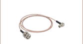
- Drive Cables Included or Attached to Mount
PIM1
Ø1" Mirror Mount, Piezo Inertia Actuators
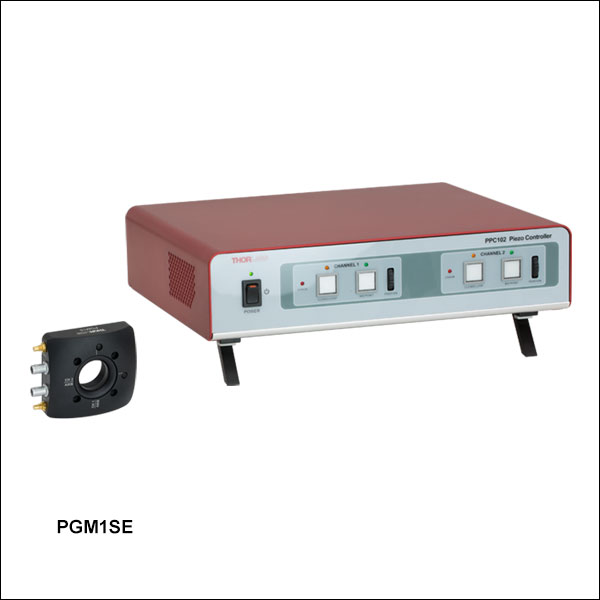
PGM1SE
Piezoelectric Gimbal Mount (Includes Controller)


Please Wait

Click to Enlarge
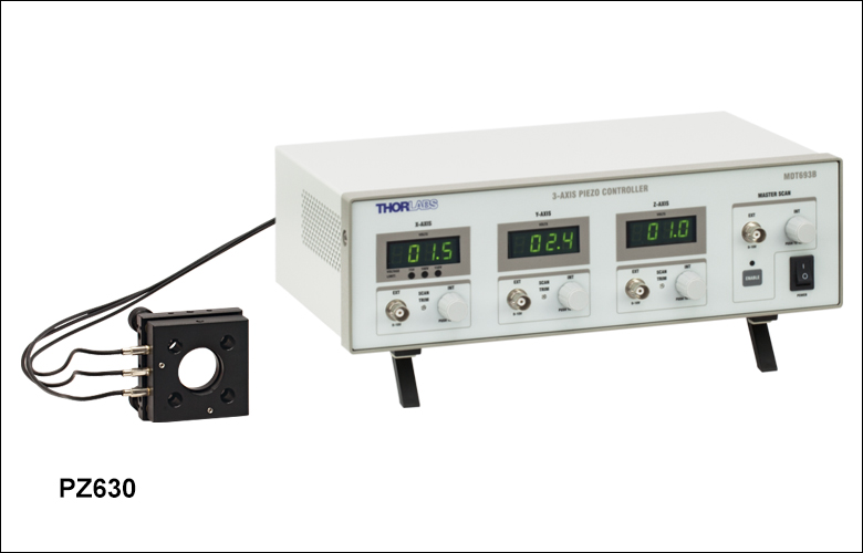
The KC1-PZ(/M) and KC1T-PZ(/M) are available bundled with the MDT693B 3-Channel Piezo Controller.
| Thorlabs' Piezoelectric Mirror Mounts | ||
|---|---|---|
| Type | Photo (Click to Enlarge) |
Features |
| Piezo Inertia Adjusters | 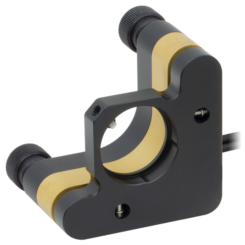 |
Actuators Maintain Position When No Power is Supplied |
| Cage-Compatible | 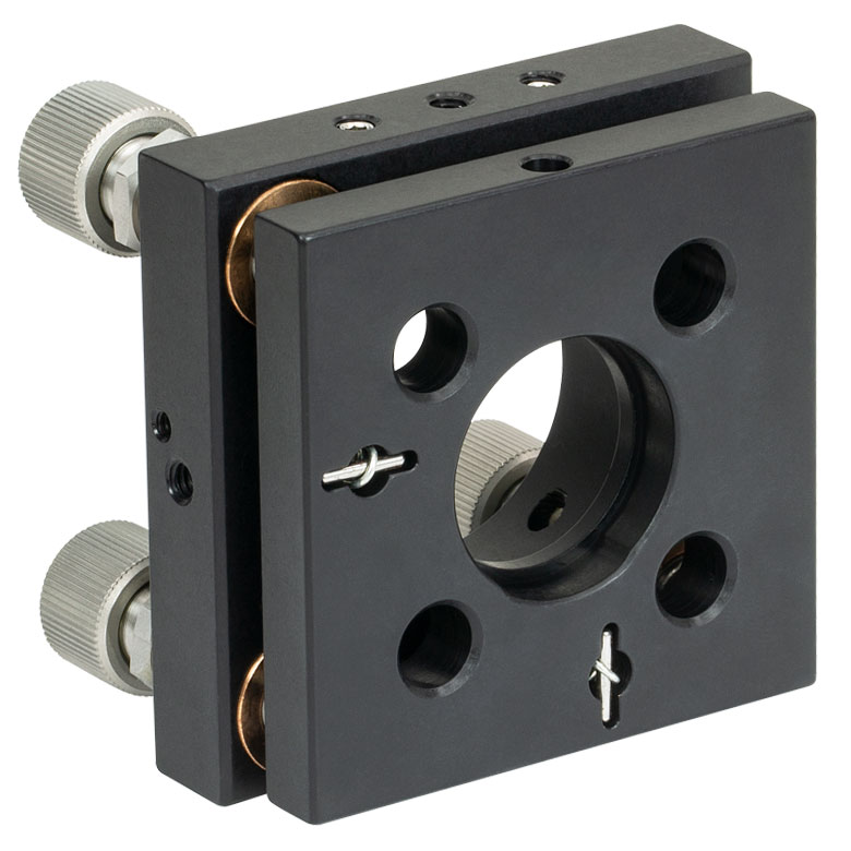 |
Three Adjusters for Pitch, Yaw, and Z Adjustment |
| Gimbal Mount |  |
Mirror Center Does Not Translate with Angular Adjustment |
| Polaris® Mounts | 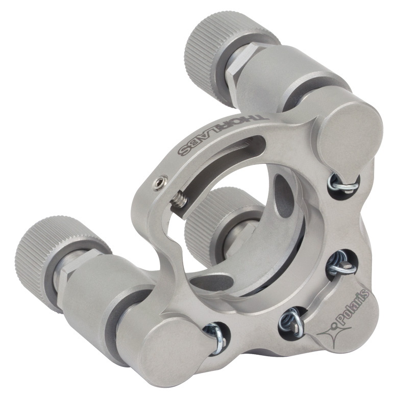 |
Long-Term Stability Over Time and Temperature Changes |
Features
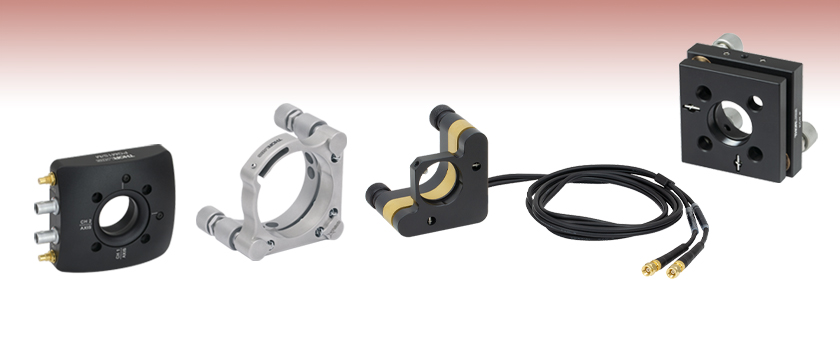
- Two-Axis or Three-Axis Mirror Mounts with Manual and Piezo Adjusters
- For Ø1/2", Ø1", or Ø2" Mirrors
- Piezo Drive Cables are Attached or Included
- Piezoelectric Inertial Motor Mounts with ±2° Angular Adjustment (Any Combination of Mechanical and Piezoelectric)
- 30 mm Cage-Compatible Optic Mounts with ±275 µrad or ±73 µrad Piezoelectric Angular Adjustment
- Piezoelectric Gimbal Mount Rotates About Center of Optic
- Polaris® Kinematic Mirror Mounts with Piezoelectric Adjusters are Designed for Exceptional Thermal and Long-Term Stability
- Compatible with Thorlabs' Piezo Controllers
The two-axis and three-axis mirror mounts sold on this page contain manual and piezo adjusters, enabling coarse and fine adjustment of the tip and tilt of a mounted optic.
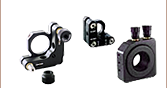
2-Adjuster Mirror Mounts with Piezo Inertia Adjusters
These mirror mounts feature a piezoelectric inertial motor design, utilizing inertia and friction to actuate the adjuster screws. Unlike other piezo adjusters, these actuators maintain their position when no power is supplied, making them ideal for applications requiring long-term stability. These mounts can achieve a wide angular adjustment range of ±2° with typical piezoelectric steps of 0.5 µrad. The piezoelectric adjusters can be driven by a KIM001 or KIM101 K-Cube™ Inertial Motor Controller (sold separately). The PIM05(/M) actuators feature a 5/64" (2 mm) hex on the end and two Ø0.09" side through holes; they can be adjusted manually using an HKTS-5/64 thumbscrew, SA1 side hole adjustment tool, or 5/64" hex key or balldriver. The PIM1(/M) adjusters feature an adjustment knob with a 5/64" (2 mm) hex on the end. Piezo inertia mounts for Ø1/2" and Ø1" optics are available.
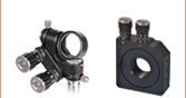
30 mm Cage Compatible Kinematic Mirror Mounts with Piezo Adjusters
Our cage-compatible piezoelectric mirror mounts feature through holes for integration into a 30 mm cage assembly. They are ideal for cage system applications that require small, repeatable angular adjustments. Our KC1-P(/M) and KC1T-P(/M) mounts offer a ±275 µrad piezo angular range, while our KC1-PZ(/M) and KC1-T-PZ(/M) mounts offer a ±73 µrad piezo angular range. All cage-compatible piezo mounts have a mechanical angular range of ±5°. The mounts are available with either a Ø1" smooth bore or an internal SM1 (1.035"-40) thread to hold a Ø1" optic. Each can also be mounted on a Ø1/2" post using the 8-32 (M4) taps. The KC1-PZ(/M) and KC1-T-PZ(/M) may also be purchased in bundles with the MDT693B Three-Channel Piezo Controller, which provides electronic control for all three axes.
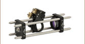
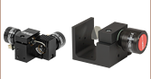
Piezoelectric Gimbal Mount
The PGM1SE(/M) is a motorized, Ø1" gimbal mount with two axes of rotation. Each axis has a piezoelectric angular range of 30 mrad with a resolution of 0.05 µrad in open-loop mode. Built-in strain gauge feedback allows for closed-loop operation, which provides a 20 mrad angular range and 0.14 µrad resolution. The mount is shipped with a factory-calibrated controller that supports the Kinesis® motion control software.
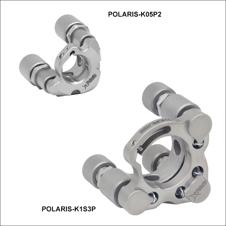
Polaris Kinematic Mirror Mounts with Piezoelectric Adjusters
The Polaris Kinematic Mirror Mounts with Piezoelectric Adjusters are the ultimate solution for applications requiring stringent, long-term alignment stability. Machined from heat-treated stainless steel, Polaris mounts utilize precision-matched adjusters with ball contacts and sapphire seats to provide smooth kinematic adjustment. These Polaris mounts use either a monolithic flexure arm or a flexure spring and setscrew combination to hold the optic. These designs provide high holding force and pointing stability with minimal optic distortion. All of the Polaris mounts with piezo adjusters have a piezoelectric angular adjustment range of at least 280 µrad, as well as a mechanical angular adjustment range of at least ±3.4°. Two-axis mirror mounts that accept Ø1/2", Ø1", or Ø2" mirrors are available. Additionally, three-axis mirror mounts that accept Ø1" mirrors are also offered. For more details, see the Polaris Kinematic Mirror Mounts with Piezoelectric Adjusters page.
Click for Details
Piezo Controller as Part of a Closed-Loop System
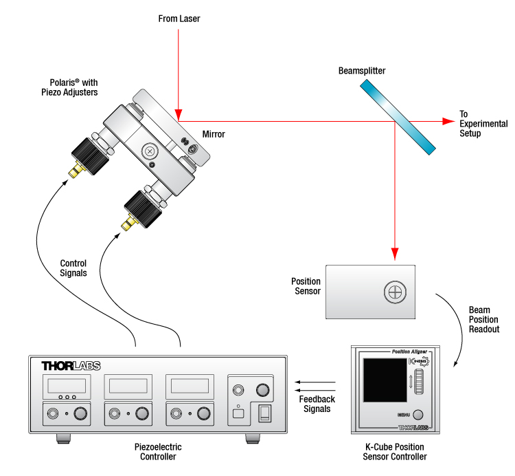
Piezo Controller in a Beam Stabilization Setup
Active beam stabilization is often used to compensate for beam drift (unintended beam pointing deviations) in experimental setups. Drift can be caused by insecurely mounted optics, laser source instabilities, and thermal fluctuations within an optomechanical setup. In addition to correcting for setup errors, active stabilization is frequently used in laser cavities to maintain a high output power or used on an optical table to ensure that long measurements will take place under constant illumination conditions. Setups with long beam paths also benefit from active stabilization, since small angular deviations in a long path will lead to significant displacements downstream.
An example of a beam stabilization setup is shown in the schematic to the left. A beamsplitter inserted in the optical path sends a sample of the beam to a quadrant position sensor that monitors the displacement of the beam relative to the detector's center. (For optimal stabilization, the beamsplitter should be as close as possible to the measurement.) The quadrant detector outputs an error signal in X and Y that is proportional to the beam's position. Each error signal is fed into a channel of a piezoelectric controller that steers the beam back to the center of the quadrant sensor.
The setup illustrated here stabilizes the beam to a point in space. In order to stabilize the beam over a beam path, four independent output channels are required (i.e., at least two piezoelectric controllers), as are two mirror mounts with piezo adjusters, two position sensors, and two position sensor controllers. Suggested electronics for a beam stabilization setup are given in the table below.
| Suggested Components | |
|---|---|
| Description | Item # |
| Mirror Mount with Piezo Adjusters (Choose One) |
KC1-PZ(/M) Mirror Mount, KC1-T-PZ(/M) Mirror Mount with SM1-Threaded Bore, POLARIS-K1S3P Polaris® Mirror Mount with 3 Adjusters, or POLARIS-K05P2, POLARIS-K1S2P, POLARIS-K2S2P Polaris® Mirror Mount with 2 Adjusters |
| Piezoelectric Controllera | MDT693B Three-Channel Benchtop Controller MDT694B Single-Channel Benchtop Controllerb, or KPC101 K-Cube™ Piezo Controller and Strain Gauge Readerb |
| Quadrant Position Detector | PDP90A (320 - 1100 nm), PDQ80A (400 - 1050 nm), or PDQ30C (1000 - 1700 nm) |
| K-Cube™ Position Sensor Controller | KPA101 |
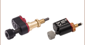
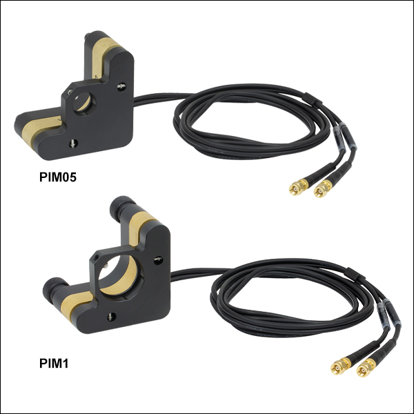
PIM05 & PIM1 Mirror Mounts
SMC Female

Input Voltage: 85 - 125 V
KC1(-T)-PZ Kinematic Mirror Mount
BNC Male
Input Voltage: 0 - 150 V
KC1(T)-P and Polaris
Kinematic Mirror Mounts
SMB Male
Input Voltage: 0 - 150 V
MDT693B Three-Channel Piezo Controller
Piezo Output
BNC Female
Output Voltage: 0 - 150 V
Output Impedance (Max): 150 Ω, 1.0 nF
External Voltage Control
BNC Female
Input Voltage: 0 - 10 V
Input Impedance: 10 kΩ
External Computer Control
Type B USB Female

Piezo Driver Bandwidth Tutorial
Knowing the rate at which a piezo is capable of changing lengths is essential in many high-speed applications. The bandwidth of a piezo controller and stack can be estimated if the following is known:
- The maximum amount of current the controllers can produce. This is 0.5 A for our BPC Series Piezo Controllers, which is the driver used in the examples below.
- The load capacitance of the piezo. The higher the capacitance, the slower the system.
- The desired signal amplitude (V), which determines the length that the piezo extends.
- The absolute maximum bandwidth of the driver, which is independent of the load being driven.
To drive the output capacitor, current is needed to charge it and to discharge it. The change in charge, dV/dt, is called the slew rate. The larger the capacitance, the more current needed:
For example, if a 100 µm stack with a capacitance of 20 µF is being driven by a BPC Series piezo controller with a maximum current of 0.5 A, the slew rate is given by
Hence, for an instantaneous voltage change from 0 V to 75 V, it would take 3 ms for the output voltage to reach 75 V.
Note: For these calculations, it is assumed that the absolute maximum bandwidth of the driver is much higher than the bandwidths calculated, and thus, driver bandwidth is not a limiting factor. Also please note that these calculations only apply for open-loop systems. In closed-loop mode, the slow response of the feedback loop puts another limit on the bandwidth.
Sinusoidal Signal
The bandwidth of the system usually refers to the system's response to a sinusoidal signal of a given amplitude. For a piezo element driven by a sinusoidal signal of peak amplitude A, peak-to-peak voltage Vpp, and frequency f, we have:
A diagram of voltage as a function of time is shown to the right. The maximum slew rate, or voltage change, is reached at t = 2nπ, (n=0, 1, 2,...) at point a in the diagram to the right:
From the first equation, above:

Thus,
For the example above, the maximum full-range (75 V) bandwidth would be
 .
.
For a smaller piezo stack with 10 times lower capacitance, the results would be 10 times better, or about 1060 Hz. Or, if the peak-to-peak signal is reduced to 7.5 V (10% max amplitude) with the 100 µm stack, again, the result would be 10 times better at about 1060 Hz.
Triangle Wave Signal
For a piezo actuator driven by a triangle wave of max voltage Vpeak and minimum voltage of 0, the slew rate is equal to the slope:
![]() .
.
Or, since f = 1/T:
Square Wave Signal
For a piezo actuator driven by a square wave of maximum voltage Vpeak and minimum voltage 0, the slew rate limits the minimum rise and fall times. In this case, the slew rate is equal to the slope while the signal is rising or falling. If tr is the minimum rise time, then
or
 .
.
For additional information about piezo theory and operation, see the Piezoelectric Tutorials page.
| Posted Comments: | |
cilong zhang
(posted 2022-03-10 18:57:04.283) I have KPZ101 (with SMC male connector) to control KC1T-P (with SMB femal connector), but the accessory connectors are SMB-BNC, so can I require SMB-SMC connectors in exchange? DJayasuriya
(posted 2022-03-11 06:59:54.0) Thank you for your inquiry. You will be able to use an adaptor to convert BNC to SMC : https://www.thorlabs.de/newgrouppage9.cfm?objectgroup_id=289. Unfortunately we do not have SMB -SMC cable at the moment. If you have any questions please get in touch with our tech support team, who would be happy to help. cilong zhang
(posted 2021-12-30 16:31:00.207) i want a right-angle kinematic cage mount with fine piezo jgreschler
(posted 2022-01-04 11:29:30.0) Thank you for reaching out to Thorlabs. I have suggested this topic to our internal product development forum. This kind of feedback helps us grow our catalogue. user
(posted 2020-02-04 15:56:53.933) As a driver for POLARIS-K1S2P, MDT694B and KPZ101 are recommended. Is there a criteria to choose which is suitable? The bandwidth and the maximum driver current are different. The controller software is different. Is there any other important difference, in particular, in the hardware spec? Is there any plan to discontinue one of them? asundararaj
(posted 2020-02-05 08:25:38.0) Thank you for contacting Thorlabs. The selection of a Piezo Controllers would depend on the required piezo drive voltage as well as the bandwidth. I have contacted you directly via email to discuss this further. mbisram
(posted 2018-08-20 17:02:51.667) Is there any documentation on how much angular deflection occurs for different voltages? Also, is the deflection standard across the mirrors? I have a thor piezo optic mirror, I am just unsure what type it is. llamb
(posted 2018-09-24 09:42:37.0) Thank you for contacting Thorlabs. We do not currently have documentation on the displacement vs. voltage for these piezos, though the angular deflection is standard across each product group. You can find the angular step sizes of each piezo mount provided in the specifications tables under the Overview tab. Keep in mind that the step size may vary because of piezo hysteresis, among other factors. While these mounts do not have a feedback mechanism, this variation can be improved by implementing an external closed loop feedback mechanism. user
(posted 2015-10-30 12:53:25.307) Can we unplug the built-in 3' (91.4 cm) cable with the male BNC connector from the mount, or will it be damaged? besembeson
(posted 2015-11-04 05:21:58.0) Response from Bweh at Thorlabs USA: No this can't be unplugged. Contact me at techsupport@thorlabs.com if you need a different cable length or have any other desired modifications. tpschwab
(posted 2013-06-10 17:00:54.437) To Thorlabs,
I have a few questions regarding the performance of the PZ631 Controller and KC1-PZ Piezoelectric Kinematic Mount:
1) What is the maximum allowable mass to be placed on the mount?
2) Once a desirable position, for the stage, is found, is it possible to return to this position by setting it as the default orientation? cdaly
(posted 2013-06-12 16:47:00.0) Response from Chris at Thorlabs: Thank you for using our feedback tool. We do not really have a well defined limit for the load spec of this mount, but we anticipate this can handle at most 1-2 pounds, but this will need to be kept at a very short moment from the mounting face of the KC1-PZ. As for the question on returning to a position, the device is simply driven by a voltage input. If you note the voltages which correspond to the desired position, you can simply apply these voltage again late to return, provided you have no moved the actuator screws. jlow
(posted 2012-09-26 16:17:00.0) Response from Jeremy at Thorlabs: Thank you very much for your feedback. We will look into the possibility of implementing your suggestion. user
(posted 2012-09-22 00:12:33.0) Would be great to label the 3 adjusters, and the three cables. bdada
(posted 2012-03-15 13:36:00.0) Response from Buki at Thorlabs:
Thank you for your feedback. KC1-PZ piezo mount has BNC connectors while the ASM003 has SMC connectors. Our MDT693 piezo controller has BNC connectors on the rear panel and also includes BNC to SMC adapters for the ASM003 mount.
On the other hand, our BPC series piezo controller has an SMC male output, so you would need an adapter, T4292, BNC to SMC female, to be able to use it with the KC1-PZ.
For reference, below is a link to our selection of compatible piezo controllers.
http://www.thorlabs.com/Navigation.cfm?Guide_ID=2085
We will expand on the compatibility issue on our website. Thank you again for your feedback. Please contact TechSupport@thorlabs.com if you have any questions. user
(posted 2012-03-07 19:08:07.0) There is mention of compatibility with T-cube piezo control, but little guidance on what makes it compatible. tor
(posted 2011-01-06 23:06:33.0) Response from Tor at Thorlabs to sema: I apologize for the inconvenience. I will send you an updated drawing; we will be including this drawing on the web shortly. sema
(posted 2011-01-06 14:26:18.0) Dear Inge, please define "within the next couple of weeks". We just bought a KC1-PZ/M, and we can neither find the cable configuration. The CAD drawings (in the package and here on the web) are still rev. E from 96. Greg
(posted 2010-04-16 14:51:39.0) A response from Greg at Thorlabs to jlarchibald: Thank you for pointing this out! I have corrected the web presentation for it. Adam
(posted 2010-04-16 14:42:01.0) A response from Adam at Thorlabs to jlarchibald: You are correct, the adjusters are 1/4-80 threaded. We will correct the typo that is on the website. jlarchibald
(posted 2010-04-16 14:36:14.0) On this webpage:
http://www.thorlabs.com/newgrouppage9.cfm?objectgroup_id=231
theres a part that claims it has 1/4"-20 Adjusters. Im pretty sure theyre 1/4"-80 Adjusters. Its listed correctly in other places.
Best,
James inge
(posted 2008-08-12 14:53:57.0) That is a very good point. We will change the drawings within the next couple of weeks. ghegenbart
(posted 2008-08-11 06:44:45.0) Unfortunately the ESDs of the KC1-PZ(/M) and KC1-T-PZ(/M) do not contain any information about which cable belongs to which actuator. |

 Zoom
Zoom| Key Specificationsa | ||
|---|---|---|
| Item # | PIM05(/M) | PIM1(/M) |
| Optic Size | Ø1/2" | Ø1" |
| Minimum Optic Thickness | 3 mm | |
| Total Angular Rangeb | ±2° | |
| Typical Step Sizec | 0.5 µrad | |
| Typical Angular Velocity | 0.05 rad/min | |
| Piezo Resonant Frequency | 125 kHz | |
| Piezo Control Voltage | 85 to 125 V | |
| Piezo Connectors | SMC Female (Channel 1 and 2 Drive Cables Attached) |
|
| Compatible Controllerd | KIM001 or KIM101e | |
| Adjusters | Manually Adjustable 80 TPI Screws with Integrated Piezoelectric Inertia Elements |
|
| Post Mounting Features | 8-32 (M4) Mounting Taps | |
| Dimensions (L x W x H) |
2.17" x 1.66" x 2.17" |
2.17" x 1.70" x 2.17" |
- Compatible with Ø1/2" or Ø1" Mirrors
- Piezo Inertia Motor Design Provides High Piezoelectric Angular Range and High-Resolution Adjustment
- Actuators Maintain Position When No Power is Supplied
- Smooth Bore with Nylon-Tipped Setscrew for Mounting Optics
- Built-In SMC Cables for Control via a KIM001 or KIM101 Controller (Sold Separately)
- 8-32 (M4) Tapped Holes for Post Mounting
The PIM05(/M) and PIM1(/M) mirror mounts feature two adjusters with integrated piezoelectric inertia actuators. These actuators provide high-resolution motion control with long piezo-controlled travel ranges in a compact package. The mounts have a ±2° angular range, which can be achieved by any combination of piezoelectric and manual adjustment. The piezo motor achieves a typical step size of 0.5 µrad, but due to the open loop design, piezo hysteresis, variance among components, and variation in application conditions, the step size may vary by 20%.
The actuators are self-locking when at rest and when there is no power supplied to the piezo, making these actuators ideal for set-and-hold applications that require sub-microradian resolution and long-term alignment stability. Manual adjustments can be made at any time, as long as the piezo is not actively translating the screw. The PIM05(/M) adjusters feature a 5/64" hex and two Ø0.09" side through holes and can be manually adjusted with the use of an HKTS-5/64 hex key thumbscrew, SA1 side hole adjustment tool, or 5/64" hex key or balldriver. The PIM1(/M) adjusters feature an adjustment knob with a 5/64" (2 mm) hex on the end.
These mounts are designed to be driven by our K-Cube™ Piezo Inertia Actuator Controllers (sold separately). Two options are available: the KIM001 single-channel controller and the KIM101 four-channel controller. Piezo drive cables with SMC female connectors for each axis are attached to the mount. The adjusters and drive cables are labeled with their respective channel numbers.
The PIM05(/M) is designed for Ø1/2" optics, while the PIM1(/M) holds Ø1" optics. Each mount has a nylon tipped setscrew with a 5/64" (2 mm) hex for securing an optic that is at least 3 mm thick. Three 8-32 (M4) tapped holes on each side of the mounts allow for post mounting in a right-handed or left-handed orientation.
Click to Enlarge
Simplified Illustration Showing the Operation of an Inertia Piezo Actuator
Piezoelectric Inertia "Slip-Stick" Motor
A piezo stack mounted perpendicular to the lead screw axis actuates the screw via a design based on the system's inertia and coefficients of friction. Two decoupled arms, or jaws, are located on either side of the piezo. These arms then extend around the top and bottom of the main lead screw. This is illustrated in the diagram to the right.
The piezo reacts to a custom sawtooth voltage waveform, causing it to expand or contract. The waveform is asymmetric, slowly ramping up to the specified voltage and then quickly dropping the voltage to zero on a nanosecond timescale. As shown in the bottom illustration in the image to the right, the jaws will "stick" to the lead screw during the slow voltage ramp, similar to how a person would turn a screw with their thumb and forefinger. The nanosecond voltage drop will cause the arms to "slip" due to the screws' inertia and the different coefficients of friction, and return the arms to their original position. The "slip-stick" nature of this device uses very short pulse widths and continuous stepping of the actuator will result in an audible noise at a typical level of 60 to 70 dB. This mechanism allows a single piezo element to translate a lead screw along its entire length.
Due to a number of factors that include the application condition, piezo hysteresis, component variance, and the axial load, the achieved step size will vary and is not repeatable. To help overcome this variance, an external feedback system will need to be used. Alternatively, a stepper motor actuator can also be substituted depending on the application.
See our individual piezoelectric inertia actuators here.

 Zoom
Zoom| Key Specifications | ||
|---|---|---|
| Piezo Specifications | ||
| Integrated Piezo Item # | POLARIS-P20a | |
| Resonant Frequency | 69 kHz | |
| Piezo Angular Range | ±275 µrad | |
| Piezo Linear Travel | ±9.7 µm | |
| Minimum Step Size | 0.37 µrad per 0.1 V Step | |
| Piezo Control Voltage | 0 to 150 V | |
| Piezo Connectors | Male SMB (Three PAA236R SMB-to-BNC Cables Included) |
|
| Mechanical Specifications | ||
| Optic Size | Ø1" (Ø25.4 mm) | |
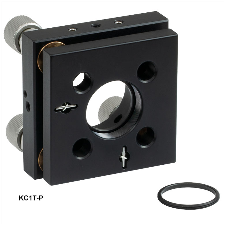
| Optic Thickness | KC1-P(/M): 0.12" (3.0 mm) (Min) KC1T-P(/M): 0.12" (3.0 mm) (Max) |
|
| Mechanical Angular Range | ±5° (±87 mrad) | |
| Mechanical Linear Travel | ±3 mm | |
| Adjusters | 100 TPI Screws with Integrated Piezos | |
| Post Mounting Features | 8-32 (M4) Mounting Taps | |
| Cage System Compatablity | Cage Rod Clearance Holes for 30 mm Cage Rods 5/64" (2 mm) Hex Locking Screws |
|
- Compatible with Ø1" Mirrors
- Available with Smooth or SM1-Threaded (1.035"-40) Central Bore
- Through Holes for Integration with a 30 mm Cage System
- SMB Connectors Accept Control Voltages up to 150 V
- Three PAA236R SMB-to-BNC Cables Included
- Mount Fabricated from Black Anodized Aluminum
- 8-32 (M4) Tapped Holes for Post Mounting
These mirror mounts, based on our KC1 mirror mounts, have three axes that can be adjusted manually or by using the integrated piezo. The
The three 100 TPI manual adjusters come with lock nuts that can be tightened by hand or with a 12 mm thin-head, open-ended hex wrench. Each actuator can be connected to a compatible controller using one of the three included 3' SMB-to-BNC cables. We recommend driving the piezo actuators with our benchtop or Kinesis K-Cube™ piezo controllers (sold separately).
| Suggested Piezo Controllersa |
|---|
| MDT693B Three-Axis Benchtop Controller |
| MDT694B Single-Axis Benchtop Controller |
| KPC101 Single-Axis K-Cube™ Controller and Strain Gauge Reader |
These mounts are 30 mm cage system compatible; the cage rods can be locked into place using the 5/64" (2 mm) hex locking screws. They are also post mountable using one of the 8-32 (M4) mounting taps located on three sides of the mount.

 Zoom
Zoom| Key Specifications | ||
|---|---|---|
| Piezo Specifications | ||
| Integrated Piezo Item # | AE0505D08Fa | |
| Resonant Frequency | 138 kHz | |
| Piezo Angular Range | ±73 µrad | |
| Piezo Linear Travel | ±4 µm | |
| Minimum Step Size | 0.3 µrad | |
| Piezo Control Voltage | 0 to 150 V | |
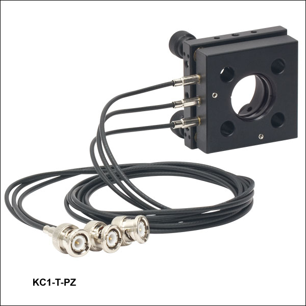
| Piezo Connectors | Integrated BNC Cables (Click for Cable Diagram) |
|
| Mechanical Specifications | ||
| Optic Size | Ø1" (Ø25.4 mm) | |
| Optic Thickness | KC1-PZ(/M): 0.12" (3.0 mm) (Min) KC1-T-PZ(/M): 0.12" (3.0 mm) (Max) |
|
| Mechanical Angular Range | ±5° (±87 mrad) | |
| Mechanical Linear Travel | ±3 mm | |
| Adjusters | Manually Adjustable 80 TPI Screws with Integrated Piezoelectric Elements |
|
| Post Mounting Features | 8-32 (M4) Mounting Taps | |
| Cage System Compatablity | Cage Rod Clearance Holes for 30 mm Cage Rods 0.05" (1.3 mm) Hex Locking Screws |
|
- Compatible with Ø1" (Ø25.4 mm) Mirrors
- Available with Smooth or SM1-Threaded (1.035"-40) Central Bore
- Through Holes for Integration with a 30 mm Cage System
- Built-In BNC Cables Accept Control Voltages up to 150 V
- Mount Fabricated from Black Anodized Aluminum
- Available with Bundled Controller (See Below)
- 8-32 (M4) Tapped Holes for Post Mounting
These mirror mounts, based upon our KC1 mirror mounts, have three axes that can be adjusted manually or by using the integrated piezo. The smooth bore version [Item # KC1-PZ(/M)] secures the mirror with a nylon-tipped 8-32 (M4) setscrew and accepts mirrors at least 5.8 mm thick, while the SM1-threaded version [Item # KC1-T-PZ(/M)] secures the mirror with two included SM1RR Retaining Rings and accepts mirrors up to 3.0 mm thick.
The 1/4"-80 manual adjusters can be locked in place using the 8-32 set screws located on the adjuster. Each piezo adjuster is connected to a built-in 3' cable with a male BNC connector, and the maximum control voltage is 150 V. These mounts are also sold bundled with the MDT693B Three-Channel Piezo Controller, providing all the components needed for open-loop control of the mount (see below for details).
| Suggested Piezo Controllersa |
|---|
| MDT693B Three-Axis Benchtop Controller |
| MDT694B Single-Axis Benchtop Controller |
| KPC101 Single-Axis K-Cube™ Controller and Strain Gauge Reader |
These mounts are 30 mm cage system compatible; the cage rods can be locked into place using the 0.05" (1.3 mm) hex locking screws. They are also post mountable using one of the three 8-32 (M4) mounting taps.

 Zoom
Zoom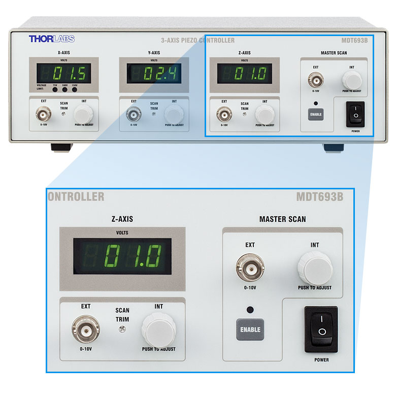
Click for Details
Front Panel of Controller
- Includes One KC1-PZ(/M) or KC1-T-PZ(/M) Mirror Mount (Shown Above)
- Bundled MDT693B Controller Includes:
- Three Output Channels with BNC Connectors and Output Voltage up to 150 V
- Controlled Directly by Front Panel or Remotely Through BNC or Command Line
- Ability to Drive All Channels with One Signal
These bundles provide all the components and cables needed for open-loop control of a three-axis kinematic mirror mount with piezo adjusters. They consist of our MDT693B Three-Channel Piezo Controller, a KC1-PZ(/M) or KC1-T-PZ(/M) mirror mount (see above for details on the mirror mount options), and a region-specific power cord selected at the time of the order.
The MDT693B piezo controller features three precise, low-noise, independently controllable output channels and is capable of supporting the piezo mirror mounts' maximum control voltage of 150 V. The control voltage can be modified using rotary knobs on the front panel and by providing an external signal through BNC or USB 2.0. The driver also includes a Master Scan mode that allows all three axes to be controlled by one signal. For more information, please see the full MDT693B presentation.
| Key Controller Specifications | ||||||
|---|---|---|---|---|---|---|
| Item # | Infoa | Number of Channels | Output Voltageb | Output Voltage Resolution | Bandwidth (-3 dB) | Connectors |
| MDT693B | 3 | 0 - 75 V | 1.1 mV | 9 kHz (No Load, Small Signal) 8.5 kHz (No Load, 150 Vpp)c 200 Hz (1.4 µF Piezo, 150 Vpp)c |
BNC (Three BNC-to-SMC Adapters Included) | |
| 0 - 100 V | 1.5 mV | |||||
| 0 - 150 V | 2.2 mV | |||||
- Click the
 icon for complete specifications.
 - Selected by Switch on Rear
- Assume a ramp function is used. The bandwidth depends upon the load and requires a calculation for a more representative number.

 Zoom
Zoom| Key Specifications | ||
|---|---|---|
| Piezo Specifications | ||
| Resonant Frequency (7.0 g Load) | 360 Hz ± 15% | |
| Piezo Angular Range | 30 mrad (Open Loop) 20 mrad (Closed Loop) |
|
| Angular Resolution | 0.05 µrad (Open Loop) 0.14 µrad (Closed Loop)a |
|
| Piezo Control Voltage | -25 to 150 V | |
| Piezo Drive Connectors | Male SMCb | |
| Strain Gauge Connectors | Male 7-Pin LEMOb | |
| Mechanical Specifications | ||
| Optic Size | Ø1.00" (Ø25.4 mm) | |
| Optic Thickness | 2 mm (0.08") Min 7.5 mm (0.30") Max |
|
| Post Mounting Features | 8-32 (M4) Mounting Taps | |
| Cage System Compatibility | Four 4-40 Taps for 30 mm Cage Rods | |
- Strain Gauge Feedback Sensors for Closed-Loop Operation
- Designed for Use with Included Controller
- True Gimbal Rotation Maintains Stationary Center Point of a Mounted Optic
- High Angular Range: 30 mrad (Open Loop) or 20 mrad (Closed Loop)
- SM1-Threaded (1.035"-40) Optic Bore for Ø1" Optics
- Through Holes for Integration with a 30 mm Cage System
The PGM1SE(/M) Piezoelectric Gimbal Mirror Mount has two axes that each rotate the mounted optic about a gimbal axis, keeping the center of the optic in a fixed position. Each axis is capable of scanning over a high piezoelectric angular range of 30 mrad with a resolution of 0.05 µrad in open-loop mode (20 mrad angular range and 0.14 µrad resolution in closed-loop mode).
A Ø1" optic can be mounted in the SM1-threaded optic bore and secured with the included SM1 retaining ring. The mount can hold optics between 2 mm and 7.5 mm thick; the optic is installed via the back of the mount, which keeps the optic surface coincident with the gimbal axes, regardless of the optic thickness. We do not recommend mounting an SM1 lens tube to the threading as it will apply excessive torque to the gimbal element.
Six 8-32 (M4) tapped holes on the optic mount allow it to be mounted on a Ø1/2" post. Additionally, four 4-40 tapped holes around the optic bore on both sides of the mount provide compatibility with 30 mm cage systems.
The mount is shipped with a piezo controller that has been factory calibrated to the specific mount and supplies a voltage of -25 to +150 VDC. Piezo control is supported through the included Kinesis® GUI, either locally using the paired controller or by using an externally supplied control voltage. The controller offers USB and RS-232 interfaces for computer control, a BNC input for the addition of external drive signals, and a BNC output that gives either positioning feedback from the mount’s built-in capacitive sensors or a signal proportional to the piezo drive voltage. In addition, a DB15 connector provides signals that can be used for synchronization with external equipment. A USB 2.0 (A to B) cable is included.
For more information on the piezoelectric gimbal mount, please see the full web presentation.

 Zoom
Zoom
| Key Specificationsa | |||
|---|---|---|---|
| Optic Size | Ø1/2" | Ø1" | Ø2" |
| Number of Adjusters | 2 | 2 or 3 | 2 |
| Optic Thickness (Min) | 0.08" (2 mm) | 0.14" (3.5 mm) | |
| Mechanical Angular Range | ±5° | ±4° | ±3.4° |
| Piezoelectric Angular Range | >490 µrad | >500 µrad | >280 µrad |
| Adjusters | Manually Adjustable 100 TPI Screws with Integrated Piezoelectric Elements |
||
| Minimum Step Size | ~0.5 µrad | ~0.18 µrad | |
| Piezo Control Voltage | 0 to 150 V | ||
| Piezo Connectors | Male SMB (SMB-to-BNC Cables Included) |
||
| Beam Deviation after Temperature Cyclingb |
<6 µrad | <1 µrad | <2 µrad |
| Mounting | Two #8 (M4) Counterbores | Four #8 (M4) Counterbores |
|
- Compatible with Ø1/2", Ø1", or Ø2" Mirrors
- Manual and Piezo Adjusters in Series
- SMB Connectors Accept Control Voltages up to 150 V
- Passivated Stainless Steel Surface Ideal for Vacuum and High-Power Laser Cavity Applications
- SMB-to-BNC Cables Included
- Custom Mount Configurations are Available by Contacting Tech Support
- #8 (M4) Counterbore for Post Mounting
- Compatible with All Thorlabs Piezo Controllers (Sold Separately)
The Polaris Kinematic Mirror Mounts with Piezoelectric Adjusters are designed to provide long-term alignment stability in closed-loop systems. They offer exceptional angular resolution of ~0.5 µrad for the Ø1/2" and Ø1" mounts and ~0.18 µrad for the Ø2" mount for a 0.1 V step via piezoelectric adjustment. We recommend driving the piezo actuators using our benchtop or Kinesis K-Cube™ piezo controllers (sold separately).
The Polaris integrated matched adjuster/body design results in greater durability and thermal performance compared to non-Polaris mirror mounts. A flexure spring and setscrew combination or monolithic flexure arm provides temperature-independent retention of the optic, unlike nylon-tipped setscrews that are sensitive to temperature fluctuations. The setscrew that adjusts the flexure spring accepts a 1/16" (1.5 mm) hex key for the Ø1/2" mirror mount, or a 0.05" (1.3 mm) hex key for the Ø1" and Ø2" mirror mounts. We strongly recommend using a torque driver for securing the optic to prevent optical surface distortion and to improve thermal stability.
| Suggested Piezo Controllersa |
|---|
| MDT693B Three-Axis Benchtop Controller |
| MDT694B Single-Axis Benchtop Controller |
| KPC101 Single-Axis K-Cube™ Controller and Strain Gauge Reader |
The mirror mounts come with two or three adjuster lock nuts that can be tightened by hand or with an 11 mm thin-head (for the Ø1/2" mount) or 12 mm thin-head (for the Ø1" and Ø2" mounts), open-ended hex wrench. Lock nuts only need to be lightly tightened to a torque of approximately 4 to 8 oz-in (0.03 to 0.06 N·m). These lock nuts hold in place the manual adjustment and will not affect the fine piezoelectric adjustment of this mount. Post mounting is provided by #8 (M4) counterbores for right- or left-handed mounting. Select mounts also include Ø2 mm alignment pin holes around the mounting counterbore, allowing for precision alignments when paired with our posts for Polaris mirror mounts.
For more details, see the Polaris Kinematic Mirror Mounts with Piezoelectric Adjusters page.