 Products Home / Motion Control Electronics / Piezo / Strain Gauge Controllers / Open-Loop Piezo Controllers
Open-Loop Piezo Controllers
- Output Voltage up to 150 V
- Controlled Directly by Front Panel or Remotely Through BNC or Command Line
- Designed for Open-Loop Systems
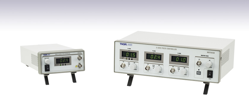
MDT694B
Single-Channel Model
MDT693B
Three-Channel Model


Please Wait
| Benchtop Motion Controllers |
|---|
| 1- and 2-Channel Brushless DC Servo Controllers |
| 1-, 2-, and 3-Channel Stepper Motor Controllers |
| 1- and 3-Channel Open Loop Piezo Controllers |
| 1- and 3-Channel Closed Loop Piezo Controllers |
| 2-Channel NanoTrak® Auto-Alignment Controller |
Click for Details
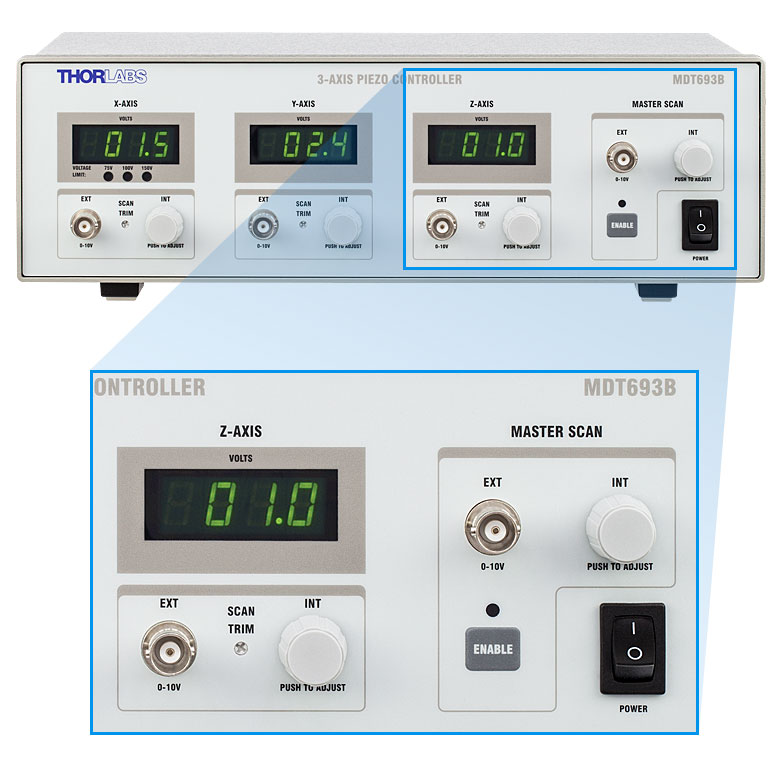
Front Panel of 3-Channel Model
Click to Enlarge
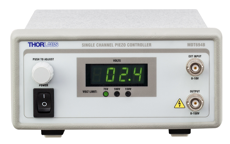
Front Panel of Single-Channel Model
Features
- Single-Channel and 3-Channel Versions
- User-Selectable Output Voltage of 0 - 75 V, 0 - 100 V, or 0 - 150 V
- Front Panel Knob(s) Provide Coarse or Fine Voltage Steps Based on Rotation Speed
- Remotely Controllable Using a Command Line or a Voltage Supplied Through BNC
- BNC Output Connectors with BNC-to-SMC Adapters Included
- 3-Channel Model Features Mode that Drives All Channels with One Signal
Thorlabs' Open-Loop Piezoelectric Controllers provide precise, low-noise output voltages for fine movement of piezoelectric actuators and stacks. Each output channel is independently controllable and provides a voltage ranging from 0 - 75 V, 0 - 100 V, or 0 - 150 V, depending upon the position of a switch on the back panel; the ability to choose a lower maximum voltage helps protect sensitive, low-voltage piezo devices. The voltage is output through BNC, and a 4-digit LED readout displays the value of the output voltage for each channel in real time. One BNC-to-SMC adapter (MDC40211) per channel is included in order to support actuators with SMC connectors.
Local and Remote Control Options
Each channel can be locally controlled by a rotary adjustment knob, remotely controlled through BNC by an external control voltage, or remotely controlled by a command-line interface. The command-line interface is accessed through USB 2.0. When using the adjustment knobs, a slow rotation will result in a small voltage step, while a fast rotation will provide larger voltage steps. The controller automatically locks the output voltage after 30 seconds to prevent accidental changes. When supplying an external control voltage through BNC, the externally supplied voltage is added to that provided by the adjustment knobs, preventing abrupt changes to the control voltage that could damage the piezoelectric capacitor. Regardless of the external control voltage's magnitude, the output voltage cannot exceed the maximum value selected on the back panel.
| Piezo Controller Bundles | |
|---|---|
 |
 |
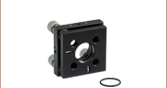
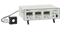
| Three-Channel Controller with Ø1" Mirror Mount |
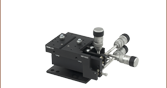
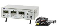
Three-Channel Controller with 3-Axis Flexure Stage |
Master Scan Mode
The MDT693B Three-Channel Open-Loop Piezo Controller features a Master Scan mode that allows all three axes to be controlled by one signal. This can be used, for example, to translate a three-adjuster mirror mount entirely in Z, without introducing tip or tilt. To accommodate differences between piezo devices, the MDT693B controller includes Scan Trim knobs that multiply the applied control voltage by a user-definable value from 80% to 120%. In addition, in Master Scan mode, the individual channel rotary adjustment knobs define a DC offset voltage.
Bundles Available
For convenience, the MDT693B three-channel piezo controller is also sold in a bundle with a three-axis NanoMax flexure stage or a Ø1" three-adjuster mirror mount, as pictured to the left.
| Other Piezo Driver Controllers | |||
|---|---|---|---|
| K-Cube™ Single-Channel Controller and Strain Gauge Reader | Open-Loop Benchtop Controller 1- and 3-Channel |
Closed-Loop Benchtop Controller 1- and 3-Channel |
Modular 2-Channel Rack System Module |
| Item # | MDT694B | MDT693B |
|---|---|---|
| Output Specifications | ||
| Number of Channels | 1 | 3 |
| Connectors | BNC (One BNC-to-SMC Adapter per Channel Included) |
|
| Output Voltage | 0 - 75 V, 0 - 100 V, or 0 - 150 V (Selected by Switch on Rear) |
|
| Output Voltage Resolution When Using Knobs |
1.1 mV (for 75 V Output Voltage Setting) 1.5 mV (for 100 V Output Voltage Setting) 2.2 mV (for 150 V Output Voltage Setting) |
|
| Output Current (Max) | 60 mA | |
| Output Noisea | 1.5 mV (RMS) ~9.9 mV (Peak-to-Peak) |
|
| Output Impedance (Max) | 150 Ω, 1.0 nF | |
| Load Impedanceb (Min) | 2.5 kΩ | |
| Bandwidth (-3 dB) | 9 kHz (No Load, Small Signal) 8.5 kHz (No Load, 150 Vpp)c 200 Hz (1.4 µF Piezo, 150 Vpp)c |
|
| Bandwidth Stability (-3 dB) | <0.01% Over 5 Hours | |
| External Control through BNC | ||
| Input Voltage | 0 - 10 V | |
| Input Impedance | 10 kΩ | |
| Input Gain | 7.5 V/V ± 5% (for 75 V Output Voltage Setting) 10 V/V ± 5% (for 100 V Output Voltage Setting) 15 V/V ± 5% (for 150 V Output Voltage Setting) |
|
| Output Voltage Resolution When Using BNC |
Limited by Noise of External Voltage Source | |
| Scan Trim Gain Adjustment | 80% to 120% of Sum of Master Scan External Voltage and Offset from Rotary Adjustment Knob |
|
| External Control through Command Line | ||
| Physical Interface | Female Type B USB 2.0 Connector | |
| Digital-to-Analog Resolution | 16-Bit, 2.75 mV | |
| Analog-to-Digital Resolution | 16-Bit, 3.0 mV | |
| Physical Specifications | ||
| Display Type | 7-Segment LED with Four Digits | |
| Display Resolution | 0.1 V | |
| Enclosure Size | 6.05" × 3.22" × 12.11" (153.6 mm × 81.8 mm × 307.6 mm) |
12.18" × 4.15" × 8.55" (309.4 mm × 105.5 mm × 217.1 mm) |
| Weight | 1.93 kg (4.25 lbs) | 3.02 kg (6.65 lbs) |
| Operating Temperature | 10 to 40 °C | |
| Power Specifications | ||
| Input Voltage | 100 - 240 VAC | |
| Input Frequency | 50 - 60 Hz | |
| Input Power (Max) | 30 VA | 60 VA |
| Fuse Type | IEC60127-2/3 (250 VA, Slow Blow, Type "T") | |
| Fuse Dimensions | 5 mm x 20 mm | |
| Fuse Rating | 500 mA | 600 mA |
Piezo Output
BNC Female
Output Voltage: 0 - 150 V
Output Impedance (Max): 150 Ω, 1.0 nF
External Voltage Control
BNC Female
Input Voltage: 0 - 10 V
Input Impedance: 10 kΩ
External Computer Control
Type B USB Female

Click for Details
Piezo Controller as Part of a Closed-Loop System
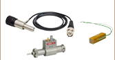
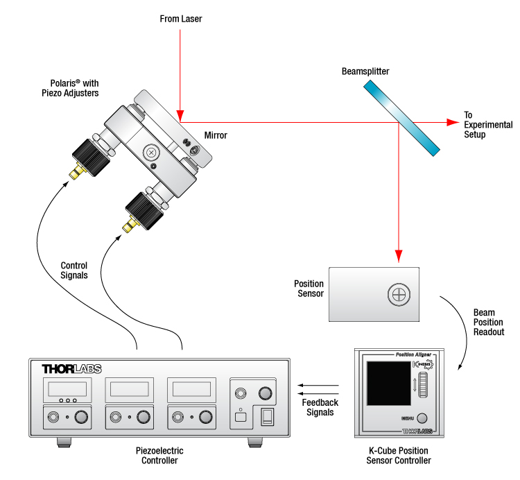
Piezo Controller in a Beam Stabilization Setup
Active beam stabilization is often used to compensate for beam drift (unintended beam pointing deviations) in experimental setups. Drift can be caused by insecurely mounted optics, laser source instabilities, and thermal fluctuations within an optomechanical setup. In addition to correcting for setup errors, active stabilization is frequently used in laser cavities to maintain a high output power or used on an optical table to ensure that long measurements will take place under constant illumination conditions. Setups with long beam paths also benefit from active stabilization, since small angular deviations in a long path will lead to significant displacements downstream.
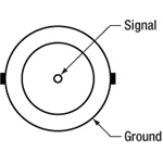
An example of a beam stabilization setup is shown in the schematic to the left. A beamsplitter inserted in the optical path sends a sample of the beam to a quadrant position sensor that monitors the displacement of the beam relative to the detector's center. (For optimal stabilization, the beamsplitter should be as close as possible to the measurement.) The quadrant detector outputs an error signal in X and Y that is proportional to the beam's position. Each error signal is fed into a channel of a piezoelectric controller that steers the beam back to the center of the quadrant sensor.
The setup illustrated here stabilizes the beam to a point in space. In order to stabilize the beam over a beam path, four independent output channels are required (i.e., at least two piezoelectric controllers), as are two mirror mounts with piezo adjusters, two position sensors, and two position sensor controllers. Suggested electronics for a beam stabilization setup are given in the table below.
| Suggested Components | |
|---|---|
| Description | Item # |
| Piezoelectric Controller | MDT693B Three-Channel Benchtop Controller or MDT694B Single-Channel Benchtop Controllersa |
| Mirror Mount with Piezo Adjusters (Choose One) |
POLARIS-K1S3P Polaris® Mirror Mount with 3 Adjusters, POLARIS-K1S2P Polaris® Mirror Mount with 2 Adjusters, KC1-PZ (KC1-PZ/M) Mirror Mount, or KC1-T-PZ (KC1-T-PZ/M) Mirror Mount with SM1-Threaded Bore |
| Quadrant Position Detector | PDP90A (320 - 1100 nm), PDQ80A (400 - 1050 nm), or PDQ30C (1000 - 1700 nm) |
| K-Cube™ Position Sensor Controller | KPA101 |
Software
Version 2.4.2
Software package with GUI and drivers to control the MDT694B and MDT693B, as well as an SDK for third-party development.
External Control Using Serial Commands
The three output channels of the MDT693B piezo controller or the MDT694B's single output channel can also be modulated remotely by sending serial commands through USB. The list of available commands is given in Chapter 7 of the manual. They include the ability to read and set voltages on a per-channel basis, to increment or decrement the control voltage at fixed step sizes, and to enable Master Scan mode (available on the MDT693B and described in the Overview tab).
Compatibility
The MDT694B and MDT693B are also backwards compatible with the software and serial commands used to control the previous-generation products (MDT694A and MDT693A).
Please note that firmware version 1.09 or later is required if using version 2 of the software. The firmware can be updated by clicking the Software link to the left.
Piezo Driver Bandwidth Tutorial
Knowing the rate at which a piezo is capable of changing lengths is essential in many high-speed applications. The bandwidth of a piezo controller and stack can be estimated if the following is known:
- The maximum amount of current the controllers can produce. This is 0.5 A for our BPC Series Piezo Controllers, which is the driver used in the examples below.
- The load capacitance of the piezo. The higher the capacitance, the slower the system.
- The desired signal amplitude (V), which determines the length that the piezo extends.
- The absolute maximum bandwidth of the driver, which is independent of the load being driven.
To drive the output capacitor, current is needed to charge it and to discharge it. The change in charge, dV/dt, is called the slew rate. The larger the capacitance, the more current needed:
For example, if a 100 µm stack with a capacitance of 20 µF is being driven by a BPC Series piezo controller with a maximum current of 0.5 A, the slew rate is given by
Hence, for an instantaneous voltage change from 0 V to 75 V, it would take 3 ms for the output voltage to reach 75 V.
Note: For these calculations, it is assumed that the absolute maximum bandwidth of the driver is much higher than the bandwidths calculated, and thus, driver bandwidth is not a limiting factor. Also please note that these calculations only apply for open-loop systems. In closed-loop mode, the slow response of the feedback loop puts another limit on the bandwidth.
Sinusoidal Signal
The bandwidth of the system usually refers to the system's response to a sinusoidal signal of a given amplitude. For a piezo element driven by a sinusoidal signal of peak amplitude A, peak-to-peak voltage Vpp, and frequency f, we have:
A diagram of voltage as a function of time is shown to the right. The maximum slew rate, or voltage change, is reached at t = 2nπ, (n=0, 1, 2,...) at point a in the diagram to the right:
From the first equation, above:

Thus,
For the example above, the maximum full-range (75 V) bandwidth would be
 .
.
For a smaller piezo stack with 10 times lower capacitance, the results would be 10 times better, or about 1060 Hz. Or, if the peak-to-peak signal is reduced to 7.5 V (10% max amplitude) with the 100 µm stack, again, the result would be 10 times better at about 1060 Hz.
Triangle Wave Signal
For a piezo actuator driven by a triangle wave of max voltage Vpeak and minimum voltage of 0, the slew rate is equal to the slope:
![]() .
.
Or, since f = 1/T:
Square Wave Signal
For a piezo actuator driven by a square wave of maximum voltage Vpeak and minimum voltage 0, the slew rate limits the minimum rise and fall times. In this case, the slew rate is equal to the slope while the signal is rising or falling. If tr is the minimum rise time, then
or
 .
.
For additional information about piezo theory and operation, see the Piezoelectric Tutorials page.
| Posted Comments: | |
user
(posted 2024-07-11 07:03:08.987) Hello,
The device has been working well for a year. Yesterday, the computer stopped recognizing it, so I updated the driver using the MDT693B Updater. This helped temporarily.
Today, the computer still does not recognize the device (tried all ports). Other computers can see the device, but it sometimes stops working correctly ( no response to command ) without any apparent error ksosnowski
(posted 2024-07-25 12:32:30.0) Thank you for reaching out to us. This could be a connection issue either from a USB cable or splitter, or potentially from sharing the host PC with too many devices. If too many devices are connected they may struggle to communicate over limited internal lanes to the CPU. For troubleshooting any issues like this you can reach us directly at techsupport@thorlabs.com. I have reached out to discuss your application in further detail. user
(posted 2024-03-13 23:08:33.257) As a user of the MDP693B, I have a query regarding its functionality when I read the recent comments.
My specific inquiry pertains to the behavior of the device in EXT mode when the INT adjustment knob is set to produce a 75 V output (@ 150V limit). In this situation, I would like to confirm whether the device allows for a control voltage range of -5 V to +5 V in EXT mode.
Your assistance in confirming this detail would be greatly appreciated. Sincerely, D.-Y. Lee. ksosnowski
(posted 2024-03-13 04:00:09.0) Hello Deok-Young, thanks for reaching out to Thorlabs. Adjusting the INT knob for DC offset inside the MDT693B does not change the range of voltage inputs or scaling, this input gets summed with the control signal's command. This system will only accept a 0 to 10V external control voltage with 15 V/V scaling in the 150V range mode. For an oscillating signal centered on a DC offset, this offset should be applied over the external control input by the waveform generator rather than the knob. There are reverse protection diodes on these inputs to help avoid passing a negative voltage into the driver, however they are not intended to continuously sink that control signal and this could damage the MDT693B if the diodes get overpowered. I have reached out directly to discuss this application in further detail. user
(posted 2023-05-10 09:44:22.76) Could you please anonymize my comment posted here below?
"We use in the Piezo Controller in several setups in our lab. It is great. I would here inform about the only problem that we have with this device. The controller support as input voltage a signal within 0V to +10V, so the "central position" is set to 5V. Now, typically an external voltage source (power supply or analog output of FPGA) when it is off is naturally at 0 V... So each time it is turned on in the central position the piezo get a strong kick to 5V. It would be nice to have the possibility to allow a "symmetric" input voltage. i.e. -10V +10V with the mid-range naturally at 0V." ksosnowski
(posted 2023-05-25 09:59:07.0) Thanks for reaching out to Thorlabs. Yes, I have removed the previous post from our site. Due to the nature of piezos, when the power supply is turned off or to zero, the piezo discharges and goes back to its relaxed, unexpanded state. Our piezos are also not designed for negative input voltages. This would require a remapping of the external modulation port voltage relative to the output, and might be best accomplished with a DAQ. However,the fact that piezos do not hold their state without power is one downside. I have reached out to discuss this in further detail. Luis Cobar
(posted 2023-05-05 13:54:26.373) I was wondering if you have an estimate of the delay between the time the MDT693B receives an external input (via BNC) and delivers an output (in the HV Output)? ksosnowski
(posted 2023-05-25 10:17:44.0) Hello Luis, thanks for reaching out to Thorlabs. We do not have the exact propagation delay nor the slew rate available for the MDT69xx models. It is negligible (~1000x faster) compared to the driving bandwidth and the actual working dynamics of piezos. The practical response to produce motion on a piezo stack with the controller is around 10Khz . That would be 35 µs rise time, assuming a low/normal piezo capacitance. Propagation delays in the internal components are typically in the nanoseconds (~100 ns), so typically faster by a factor of 1000. This is why we do not further characterize the input delay. Eli Slenders
(posted 2023-01-03 13:58:55.703) Dear sir, madam,
In our lab we are using the MDT693B controller with a 3 axis Nano-max piezo stage. We are sending commands to the controller in python using the serial library, e.g.:
pzt = PZTclass(port='COM4')
command = 'xvoltage=70.07\r'
output = pzt.write(command.encode())
with PZTclass containing the following initialization command.
serial.Serial.__init__(self, port, baudrate, timeout=0.1)
The communication works but the response from the driver is not completely as expected. The number we send and the number on the screen of the driver do not fully correspond. In the two columns below, you can find respectively the commands we send and the numbers that appears on the screen.
13.00 -> 13.03
13.50 -> 13.53
22.00 -> 22.01
40.00 -> 39.94
40.05 -> 39.99
40.06 -> 40.01
50.47 -> 50.38
53.00 -> 52.91
63.00 -> 62.89
70.07 -> 69.96
In some cases, the difference is more than 0.10 V, which is about 30 nm. In addition, when you send a command, then use the knob, and then send the same command again, the new number may slightly differ from the original one. Is this expected for this driver? Is it because of the limited precision?
Thank you very much for your answers.
Kind regards,
Eli Slenders ksosnowski
(posted 2023-01-10 04:16:01.0) Hello Eli, thanks for reaching out to Thorlabs. The MDT693B display reads an output from an ADC that measures the output in real time. When a command is sent from the computer interface to reach a particular value, there is a calculation performed to determine the internal settings to achieve that voltage. Since this is not done in a closed loop, it is possible for there to be small error between the value sent and the value that shows up on a display. We do not have an official specification for this discrepancy, but we estimate 5% is not unreasonable. We do however expect any error to be consistent, so it is possible to determine what set point should be sent to obtain the desired output more precisely. user
(posted 2022-08-11 15:18:04.06) hello,
I am trying to control the MDT693B in python with the provided drivers/dll. As the name of the DLL suggests ("MDT_COMMAND_LIB_win32.dll") it seems to be a 32-bit driver, and I'm running on a 64-bit machine, as virtually all machines are now. Trying to run the python examples gives errors that confirm this is a 32-bit DLL. Please re-compile this DLL for 64-bit machines. ksosnowski
(posted 2022-08-17 10:20:19.0) Thanks for reaching out to Thorlabs. The MDT software comes with a 64 bit library in the C++ sample location. You will need to move this to the python library location and change the Load line to: mdtLib = cdll.LoadLibrary("MDT_COMMAND_LIB_x64.dll") . cilong zhang
(posted 2022-02-21 13:02:25.427) Hello, I recently purchased the unit MDT694B and want to learn about controlling it using Micro-manager scripts. Could someone help put me in the correct direction in terms of getting started? Harold Hollis
(posted 2021-05-12 14:06:37.147) I'm interested in using several MDT693B units in an experiment. First, I need to check the type of internal power supply - is it linear or switching? cdolbashian
(posted 2021-06-04 12:14:51.0) Thank you for reaching out to us via the feedback system! The MDT693B has a AC/DC switching supply that allows for the input of 100-240 VAC. user
(posted 2021-04-13 20:30:26.17) Hello, I recently purchased the unit MDT694B and want to learn about controlling it using MATLAB scripts. Could someone help put me in the correct direction in terms of getting started? cdolbashian
(posted 2021-06-04 04:54:30.0) Thank you for reaching out to us here at Thorlabs. We do not have any direct support for Matlab control, though you can supply this controller with low-level commands via the serial port on the device. These commands, found in the manual, should be able to be interpreted via a serial port object in a Matlab environment. Tobias Witting
(posted 2020-08-12 12:26:53.747) We would like to control the MDT693B via USB. The device freezes after sending approximately 260 commands. I am sending the command: ser.write(b'xvoltage=%.2f\r' % y ) asundararaj
(posted 2020-08-14 04:11:02.0) Thank you for contacting Thorlabs. I have reached out to you via email to troubleshoot. Hussam Kloub
(posted 2020-04-28 10:39:47.973) I recently purchased the MDT693B.
Is it possible to use the corresponding GUI software to apply three different Pulse signals but each with specific time offset. For example:
signal X = Pulse_signal(10 V, 1 Hz, 0 sec time-offset)
signal Y = Pulse_signal(5 V, 0.5 Hz, 0.5 sec time-offset)
signal Z = Pulse-signal(10 V, 1 Hz, 1.0 sec time-offset) YLohia
(posted 2020-04-28 10:29:13.0) Hello Hussam, thank you for contacting Thorlabs. Unfortunately, the GUI software cannot offer a delayed start function. You can, however, set phase offset's between your signals. So after, say, 1 second of all three signals running, it would appear that the signals had started at different times. Alternately, you can create your own program with the included SDK to have a start delay between the three signals. user
(posted 2019-09-09 16:21:33.907) Hi,
This product is a little too expensive for me. I would appreciate if Thorlabs could provide me a discount on this product. Is there are any alternative to this which is cheaper and compatible to PB4VB2W Peizo electric bender usage? Tq.
Youven asundararaj
(posted 2019-09-09 10:17:06.0) Thank you for your Feedback. With the Piezoelectric Benders (such as PB4VB2W), any voltage driver with a voltage limit of at least 150 V can be used; for example, the KPZ101 is one such controller. We try to offer different options at different price points for our customers. Please review our discount policy here : https://www.thorlabs.com/discountPolicy.cfm Nikhil Sethia
(posted 2019-06-17 08:57:53.97) What is the highest frequency sine waves that I could generate using this device ? YLohia
(posted 2019-06-17 11:43:09.0) Hello, the bandwidth as given in the Specs tab is as follows:
9 kHz (No Load, Small Signal)
8.5 kHz (No Load, 150 Vpp)
200 Hz (1.4 µF Piezo, 150 Vpp)
Please note that this driver does not have an internal signal generator. kdhyun6
(posted 2019-03-05 17:45:52.937) Does this device support floating power supply?
From my knowledge, it should be, but there is no comment or circuit diagram to say it uses floating ground.
Thank you.
Best,
Dohyeon Kwon llamb
(posted 2019-03-07 03:45:01.0) Hello Dohyeon, thank you for your feedback. Both the ground of the BNC connectors and the chassis of the product are connected to the ground line on the AC input cable, so it is not floating. xw15
(posted 2019-01-30 01:17:31.073) Hi. I'm using MDT693B but I can't find the CD and there is no information about how to use this together with labview. And when I use the software download from your website, the nanomax stage didn't move. Can you offer some help YLohia
(posted 2019-01-31 10:32:25.0) Hello, thank you for contacting Thorlabs. Please use this link to download the software and update the firmware on your MDT : https://www.thorlabschina.cn/software_pages/ViewSoftwarePage.cfm?Code=MDT69xB.
We include an SDK for LabVIEW in the installation folder : C:\Program Files (x86)\Thorlabs\MDT69XB\Sample\MDT69XB SDK Manual.pdf evt.tools
(posted 2018-06-29 10:55:03.45) Hello
Give me pls customs code open loop piezo controller MDT694B Single-Channel Model
Kind regards,
Namik Guliev llamb
(posted 2018-07-07 11:56:13.0) Hello Namik, thank you for contacting Thorlabs. While we do not provide custom programming codes, we would be happy to troubleshoot any issues you may be seeing. I will reach out to you directly to discuss further. hsong41
(posted 2016-07-03 16:50:41.503) I'm using MDT694B with the software what you give and labview. However, when I generate sine signal as an input with 2 Hz (frequency), the controller was suddenly stopped. Also, within low frequency, the controller couldn't receive all of signal points. How can I generate periodic signal with high frequency? Is it possible? dean.salisbury
(posted 2016-03-14 08:36:18.857) My company uses a MDT694B, Single-Channel Mode.
The unit has a CE mark, however, I'm looking for a CB report and test certificate for S2 compliance. A CB test report and certificate typically contain the IEC Standard or IECEE CB Scheme symbols. besembeson
(posted 2016-03-14 05:24:08.0) Response from Bweh at Thorlabs USA: I will contact you regarding this please. besembeson
(posted 2015-09-23 05:18:09.0) Response from Bweh at Thorlabs USA: I will be contacting you by email to further discuss this. andrew_choo
(posted 2015-08-25 23:46:38.143) Hi may I know how to calibrate my product? I have a MDT694B and the value on the controller and LabView are sometimes the same, and sometimes different. Also, sometimes LabView does and does not detect the controller. Is there a way to fix this? besembeson
(posted 2015-09-25 03:45:16.0) Response from Bweh at Thorlabs USA: I will follow-up with you. alexshakouri
(posted 2015-07-22 10:12:45.2) I am having a problem with the MDT693b connection to my computer. For some reason it will randomly disconnect from my computer and I won't be able to control it from the computer anymore. It would also randomly connect back to my computer. I tried to uninstall the driver and reinstall, but when I use the CD it just says to installed the driver again. I also can't find out where the driver for the MDT693b is located, even though I installed it according to the CD instructions. Any help would be much appreciated! besembeson
(posted 2015-07-23 05:38:24.0) Response from Bweh at Thorlabs: I will followup with you by email. stefan.breuer
(posted 2015-03-10 18:51:23.877) Dear Thorlabs team, is it possible to apply an AC voltage to the EXT input of a MDT693A? We intend to modulate the piezo voltage below 100 Hz. Thank you in advance. Kind regards, Stefan Breuer jlow
(posted 2015-03-24 11:42:59.0) Response from Jeremy at Thorlabs: Yes, you can input an AC voltage signal to the EXT INPUT on the unit. The max. input voltage is 10V and the voltage gain is either 7.5X, 10X, or 15X, depending on the output voltage range setting. emmerich
(posted 2014-10-08 11:47:36.79) Hello, I just performed the firmware update for the MDT693B and I'm stuck at the point where I SHOULD NOT turn off the update program, but cycle the power button of the device. Windows 7 tells me that it doesn't recognize any working device and it has been deactivated once I switch the device back on. What should I do? Thank you!! jlow
(posted 2014-10-08 04:00:22.0) Response from Jeremy at Thorlabs: We have contacted you directly to troubleshoot this. jlow
(posted 2013-01-22 10:27:00.0) Response from Jeremy at Thorlabs: You should be able to communicate with the MDT69xA in Matlab. There are some resources using serial command in Matlab at the following two links to get you started:
http://www.mathworks.com/help/matlab/matlab_external/getting-started-with-serial-i-o.html
http://www.mathworks.com/help/matlab/ref/serial.html
Please make sure that the settings for the COM port can be found on page 19 of the manual (http://www.thorlabs.com/Thorcat/12500/MDT693A-Manual.pdf). Pages 20-21 are the commands for communicating with the driver. jtamez1983
(posted 2013-01-21 19:42:01.85) Hello, I am trying to control the MDT693A via Matlab, however I am having some difficulties sending the commands. It has only worked once and the values never display after. I can't find the error in my code. Has anyone else try this on matlab or VB? thanks. jlow
(posted 2013-01-14 13:37:00.0) Response from Jeremy at Thorlabs: The code given is just a sample for using the VISA serial write and read with the driver. One of the more common issue with this is that one would need to manually configure the COM port. You will have to select the correct COM port (look under Device Manager in your computer) and then input the settings. The settings for the COM port can be found on page 19 of the manual (http://www.thorlabs.com/Thorcat/12500/MDT693A-Manual.pdf). Pages 20-21 are the commands for communicating with the driver. david.n.hutch
(posted 2013-01-09 15:04:15.297) Hi. Thanks for putting up the LabVIEW code. (For other users: it's at http://www.thorlabs.us/software_pages/ViewSoftwarePage.cfm?Code=MDT693A, click Libraries tab). However there is no documentation and it's not clear to me what the "Flow Controls etc" buttons/values are supposed to do. I've tried a few different things but the LabVIEW code doesn't appear to work for me. (Note that the specific Thorlabs Mdt69xA software works just fine, so my computer can communicate with the instrument, it's just the LabVIEW code that doesn't seem to work -- but I'm not sure if I'm doing it right. jlow
(posted 2012-09-05 15:36:00.0) Response from Jeremy at Thorlabs: I will e-mail you the library for this directly. We are going to be adding this to our software download page shortly. pedrotamez9
(posted 2012-09-05 13:26:50.0) Can someone tell where I can find the LabView library to communicate with MDT693A? Thank you. jlow
(posted 2012-08-02 14:27:00.0) Response from Jeremy at Thorlabs: The MDT69xA uses serial communication. The main LabVIEW functions to use would be under "Instrument I/O" -> "VISA". I will contact you directly to send you the LabVIEW library file. kenjunderwood
(posted 2012-08-02 13:50:45.0) I'm attempting to control my MDT694A using LabVIEW 2011, and while the Thorlabs GUI control works fine, I'm not sure how to implement the serial controls into LabVIEW as recommended in the manual. It says that the software is completely compatible with LabVIEW, but I haven't found a way to bridge the two. Previous comments suggest the existence a LabVIEW library for the MDT694A, as well. Would it be possible to get a copy of that library, or possibly some help using the MDT69xA software with LabVIEW? Thanks! tcohen
(posted 2012-04-12 10:51:00.0) Response from Tim at Thorlabs: The MDT694A can communicate via the serial output RS-232 port using a standard DB9 male to DB9 female cable. The serial command syntax can be found in the manual at http://www.thorlabs.com/Thorcat/12500/12534-D02.pdf. I will contact you with the LabVIEW library and to further discuss your application. lsanfelici
(posted 2012-04-11 21:19:38.0) Dear Tholabs colleague, I'm about to start interfacing the MTD694A unit thought LabView 2011 in order to close a loop, and definetely I don't want to broke the unit's firmware. 1) Could you please send me instructions on how to avoid that? Or how to succeed in making this communication happen? 2) Also, any Labview library is super welcome! 3) Is the communication cable is just a pin to pin serial cable? (Guys in the lab lost the original one) Many thanks! tcohen
(posted 2012-04-04 15:28:00.0) Response from Tim at Thorlabs: Thank you for your feedback. I have contacted you with the LabVIEW library file. reuble
(posted 2012-04-02 21:37:09.0) Hi, Would you happen to have a LabVIEW dll or a sample program for the MDT693A controller? I'm having trouble getting the serial communication to work. 274057062
(posted 2012-03-20 22:06:37.0) Hello. Can your piezo controllers drive piezo devices sold by other companies? bdada
(posted 2012-02-17 12:50:00.0) Response from Buki at Thorlabs to nbdpw:
We are glad to hear the problem has been resolved. Please contact TechSupport@thorlabs.com if you have additional questions. nbdpw
(posted 2012-02-17 04:18:26.0) Thank you for the software. My problem has been resolved. ATTENTION anyone else who is having the 'echo' problem when communicating via MATLAB! Check which terminator your code is using. The MATLAB default is 'LF', but the MDT693A units use 'CR'. bdada
(posted 2012-02-15 18:56:00.0) Response from Buki at Thorlabs to nbdpw:
I have added the CDROM to our ftp site and will contact you with more information. nbdpw
(posted 2012-02-14 18:38:02.0) Hello, sorry, I guess I did not select "Contact Me" when I submitted the last feedback. Please do contact me in order to resolve my two issues. 1 - I require the control software, as shown on the software page, not a firmware update. 2 - I need to know how to get the MDT693A device out of echo mode. Thank you. nbdpw
(posted 2012-02-07 22:12:44.0) Hello, I am also having the same echo mode issue as the other users here. Could I please be told how to recalibrate the MDT693A unit?
Also, the link provided is for MDT693A FIRMWARE. I require the control software, not the firmware. bdada
(posted 2012-01-25 14:21:00.0) Response from Buki at Thorlabs:
Here is a link to download the software of the MDT693A: http://www.thorlabs.com/software/MDT693AVers301.zip bdada
(posted 2012-01-24 12:47:00.0) Response from Buki at Thorlabs:
Thank you for using our feedback forum. We have emailed you information on how to download the software from our ftp site. nbdpw
(posted 2012-01-23 19:39:11.0) We purchased the MDT693A, but have lost the software that comes with it. I do not see a link available for it to be downloaded from this website.
How would we go about acquiring another copy? bdada
(posted 2011-12-13 16:29:00.0) Response from Buki at Thorlabs:
We are sorry to hear about the problem you are experiencing. We have contacted you to get more information about your set up and provide you with some troubleshooting tips. byungchae.kim
(posted 2011-12-12 00:46:38.0) I am trying to control output voltage of MDT693A with MATLAB through serial port. While it seems communication itself is working, the displayed voltage change in MDT693A is quite random even though I set same output voltage repeatedly. Can you help me to solve this problem asap? bdada
(posted 2011-11-14 23:35:00.0) Response from Buki at Thorlabs:
Thank you for participating in our Feedback Forum. We have contacted you with the calibration procedure and to provide additional support. optmg
(posted 2011-11-14 12:15:34.0) sorry, our machine is MDT693A previously, I typed it wrongly. optmg
(posted 2011-11-12 14:30:57.0) I have the same problem with my MDT694A with many of the users. The serial read returns the written command both to my MATLAB program and with HyperTerminal. Should I do the calibration too? wait for your contact. Thanks jjurado
(posted 2011-08-18 17:19:00.0) Response from Javier at Thorlabs to natalia.bruno: We will send you a document with instructions for the calibration procedure. I will also send a dll file for developing your own LabVIEW vi. natalia.bruno
(posted 2011-08-18 14:48:27.0) I think I have corrupted the calibration of the MDT694A using LabView. The voltage is now ~36,7 volts, almost half of the maximum limit voltage, and even the software provided from Thorlabs is no longer able to control the device. Do I have to send it back or can you provide me the calibration procedure? It seems some other users also have this problem (see the feedback page on thorlabs website or on the National Instrument forum ).
-->
> It would be nice if Thorlabs could provide a Labview VI example for this controller. frank.xie
(posted 2011-07-07 15:03:03.0) I have had some issues communicating with this device through LabView. I have been trying to use the LabView Basic Serial Read and Write VI with this machine; however, the machine does not carry out any command I send until I exit out of LabView and run the ThorLabs software. The ThorLabs software will merely send a message telling me to "cycle the power" and will then close. jjurado
(posted 2011-06-27 16:45:00.0) Response from Javier at Thorlabs to frank.xie: Thank you very much for contacting us. I will contact you directly to help you troubleshoot your application. frank.xie
(posted 2011-06-27 11:57:30.0) Im having the same problem as many of the other posters, and I need to recalibrate this device. Id appreciate any feedback on how to do so. Customer Email: frank.xie@okstate.edu This customer would like to be contacted. jjurado
(posted 2011-05-10 13:34:00.0) Response from Javier at Thorlabs to florian.lemounier: Thank you very much for contacting us. It looks like the calibration data for the MDT controller has been lost, which is often caused by a LabVIEW serial issue. I will contact you directly with some troubleshooting tips. florian.lemounier
(posted 2011-05-10 10:41:06.0) I have the same problem as gillett. The serial read returns the command written both with Labview and HyperTerminal.
I tried to disable the echo mode sending the command E but it doesnt change anything. bdada
(posted 2011-03-07 13:23:00.0) Response from Buki:
The calibration data stored in the ePROM of the MDT693A controller was corrupted. This can happen in a LabVIEW read/write serial method. Somehow the LabView code gets into the uController and corrupts this file. The only way to recover from this is to re-calibrate the controller using a DVM and a couple of BNC cables.
We have sent you a simple LabVIEW serial protocol lib for the MTD693A. zjg1984
(posted 2011-03-04 22:28:36.0) I think I got corrupted controller, too! I was trying to control our new MDT693A with the Labview VI - Basic Serial Write and Read, suddenly all three axis show ~38.9 volts, and I cannot go lower than that. It seems some users also have this problem. It would be nice if Thorlabs could provide a Labview VI example for this controller. Thorlabs
(posted 2010-09-14 16:44:26.0) Response from Javier at Thorlabs to Patrick: It sure sounds like the MDT693A lost its calibration file that is embedded in the uController. When this happens a channel, depending on the max HV setting (75,100,150) shows up at around half of the max value. The only way to correct this is to calibrate the unit. It requires a BNC cable, a DVM, and a PC running a terminal emulator (such as Hyper Terminal) and the procedure document. We can send you this document or get the unit back and implement the calibration here. patrick.lu
(posted 2010-09-14 03:20:21.0) I seemed to have corrupted the controller when I was trying to get it to interface with LabView. Now, no matter what I do, I cant get the voltages to go below 21.7, 77.4, and 77.9 for x, y, and z, respectively. Previously, I was able to get the controller to respond to commands in hyperterminal but that no longer seems possible. Adam
(posted 2010-05-19 09:25:05.0) A response from Adam at Thorlabs to gillett: The ASCII command E, or an ASCII string "E\r" will disable verbose echo. You may want to try this using Hyper Terminal (or any other terminal emulator). Please also note that we now have an option for our customers to discuss software related questions with other users via our Brainwave forum. A link to this forum can be found below:
http://forums.thorlabs.com/profile.php?mode=register gillett
(posted 2010-05-19 00:09:30.0) We have bought 3 MDT693A, The provided software works fine. We cannot use Labview to talk to them.
Using serial write and read just echos the input.
IE writing I\n returns I\n when read is used.
The device seems to be in echo mode, with no way of getting it out.
If after using the labview code the provided software is used, it asks that the the power on the MDT693A be cycled, after doing so the provided software works again. Adam
(posted 2010-04-23 09:54:15.0) A response from Adam at Thorlabs to Jikim: The graphic user interface is suffient to control the X, Y, and Z channels independently. jikim
(posted 2010-04-23 08:45:10.0) I have already read the manual of this device, but still Im not sure if one can independently control the output characters of 3 output BNCs using the provided graphic program. For my purpose, it is very demanded to control the parameters of channel X,Y, and Z independently, e.g. amplitude, waveform function, phase etc. Is the graphical interface program sufficient for this purpose, or should I implement a computer interface by the commercial programs (Labview)? Adam
(posted 2010-04-06 09:36:36.0) A response from Adam at Thorlabs to abdul: I am sorry to hear that the MDT693A was corrupted. We can send over the calibration instructions. I will email you directly with this information. klee
(posted 2009-12-14 20:25:11.0) A response from Ken at Thorlabs to c.j.vanvoskuilen: The MDT693A/694A has RS232 interface so LabView support can be direct from using the VISA serial protocol and ASCII commands described in Section 9.4 in the manual. c.j.vanvoskuilen
(posted 2009-12-14 17:10:20.0) On your website it says that the MDT693A is readily usable with Labview. I have it, together with the latest software from your website, but cannot see how to interface it with Labview (no files provided). The manual also provides no clues. Can you help me? klee
(posted 2009-07-14 18:14:56.0) A response from Ken at Thorlabs to cherryhuang0120: The software is available for download in out Download page. Click on the Service at the top of the page and then choose Download. Scroll towards the bottom and you will see the MDT693 software. cherryhuang0120
(posted 2009-07-14 08:53:23.0) Hi,
We bought MDT693 several years ago. However, I can not find any link to download the controlling software to operate it by PC. Could you kind please to send me a zip file of the software or just give me a link to download it? Or, can you give me some LabVIEW code for helping us to start programming?
Thank you.
Best regards,
Cherry Tyler
(posted 2009-03-13 07:41:08.0) A response from Tyler at Thorlabs to susumukuma: It is likely that the firmware calibration needs to be corrected. A member of our technical support department will be in contact with you to help resolve this issue. susumukuma
(posted 2009-03-11 06:52:17.0) We purchased two MDT694A piezo controllers very recently.
The provided self-executable program with them worked fine, but not enough for our purpose. We need to scan voltages with smaller steps that the software can control.
We tried to use Labview for that purpose. But we could not find any VIs on the CD-ROM included and
the Thorlabs website. So we used the Basic Serial Write and Read.vi of Labview8 for check. By inputting the command XV, we could get the desired voltage, within the maximum value set by XL.
After several-time tries, MDT694A became not responsible suddenly. The controller display showed ~38 V and the command XV? returned no value. Even the provided software could not work properly now.
On the National Instruments site, I found people with the same problem. Please see the following link:
http://forums.ni.com/ni/board/message?board.id=140&thread.id=17790
Could you give me any advice?
Susumu Kuma
Department of Chemistry, The University of British Columbia |