 Products Home / Multi-Axis Stages / 3-Axis Stages / 3-Axis NanoMax Flexure Stage with Bundled Controller
3-Axis NanoMax Flexure Stage with Bundled Controller
- 3-Axis Piezo Flexure Stage with Compatible Controller
- 4 mm of Manual Travel for Each Axis
- Piezo Actuators Provide 20 µm of High-Resolution Displacement
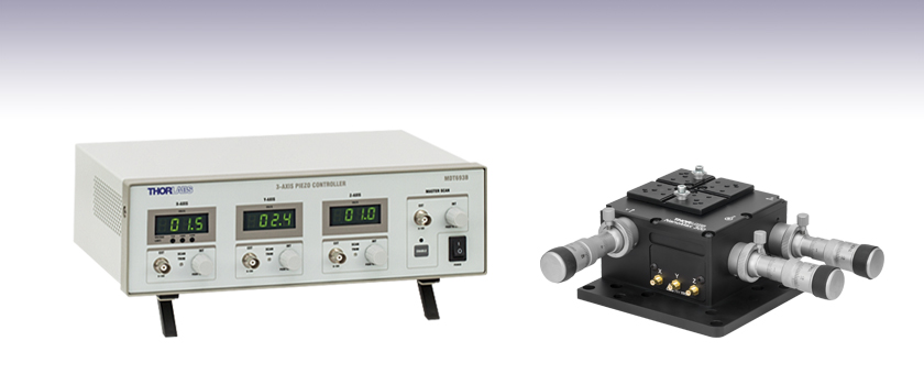
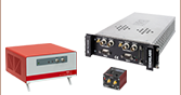
Three-Channel Piezo Controller
MDT630B
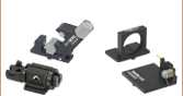
Three-Axis Flexure Stage with
Differential Micrometers Installed


Please Wait
Click for Details
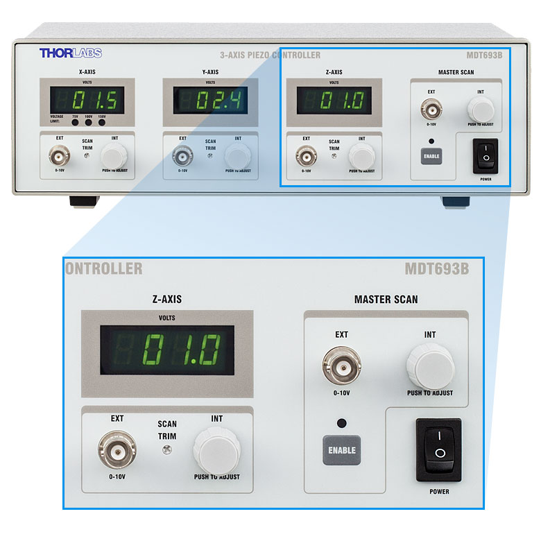
Front Panel of MDT693B Controller
Click to Enlarge
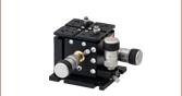
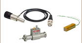
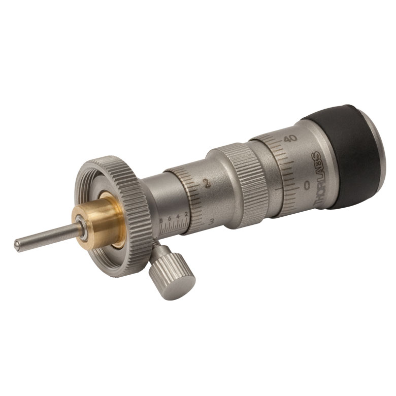
DRV3 Micrometer with Coarse and Fine Adjustment
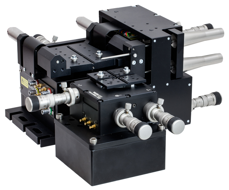
This bundle consists of the MAX302(/M) 3-Axis NanoMax Flexure Stage, three DRV3 Differential Micrometers, and the MDT693B Three-Channel Piezo Controller at a savings over purchasing these items separately. Together, these items provide local and remote control of the position of our MAX302 NanoMax stage along X, Y, and Z with sub-micron resolution. Each axis has a maximum travel range of 4 mm. The DRV3 differential micrometers provide 4 mm of coarse travel and 300 µm of fine travel, with a calculated fine resolution of 100 nm. The embedded piezo elements provide an additional 20 µm of fine travel.
This bundle includes three SMC cables, three SMC-to-BNC adapters (MDC40211), and a region-specific power cord selected at the time of the order.
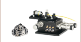
MAX302 3-Axis NanoMax Flexure Stage
Designed for alignment applications requiring sub-micron resolution, the patented flexure design of the MAX302 ensures low crosstalk, high stability, and long-term reliability. This stage is compatible with our entire family of flexure stage accessories. In a typical multi-axis stacked stage, touching one of the two axes that are not referenced to "ground" will result in unwanted motion within the assembly. Since each of the axes in a NanoMax stage are coupled directly to the base of the stage, these adverse effects are eliminated. For more information, please see the full MAX302 presentation.
DRV3 Differential Micrometer
The DRV3 features two large knobs for coarse and fine adjustment. The coarse adjuster knob provides 500 µm/rev over a 4 mm range, while the fine adjuster knob provides 50 µm/rev over a 300 µm range. The calculated fine drive resolution is 100 nm. The rubber grip on the fine adjuster knob reduces heat transfer when making small adjustments, improving stability. For more information, please see the full DRV3 presentation.
MDT693B Three-Channel Open-Loop Piezo Controller
The MDT693B piezo controller features three precise, low-noise, independently controllable output channels and is capable of supporting the MAX302's absolute maximum control voltage of 75 V. The control voltage can be modified using rotary knobs on the front panel and by providing an external signal through BNC or USB 2.0. For more information, please see the full MDT693B presentation.
MAX302 Three-Axis Flexure Stage
| Item # | MAX302(/M) |
|---|---|
| General Specifications | |
| Travel per Axis | 4 mm |
| Load Capacity | <1.54 lbs (<0.7 kg) Recommended 2.2 lbs (1 kg) Max |
| Thermal Stability | 1 µm/°C |
| Deck Height | 2.46" (62.5 mm) |
| Optical Axis Height | 2.95" (75 mm) |
| Weight | 1.65 lbs (0.75 kg) |
| Piezo Specifications | |
| Piezo Voltage Range | 0 - 75 V |
| Piezo Travel Range | 20 µm +0.2 µm / -0.0µm |
| Piezo Bidirectional Repeatability | 0.2 µm |
| Piezo Absolute On-Axis Accuracy | 1.0 µm |
| Resonant Frequency | 375 Hz (No Load) 200 Hz (275 g Load) 150 Hz (575 g Load) |
| Arcuate Cross Talk | |||
|---|---|---|---|
| As a Function of X-Axis Positiona | As a Function of Z-Axis Positionb | ||
| X-Axis Position | Arcuate Motion in Z-Axis |
Z-Axis Position | Arcuate Motion in X-Axis |
| 0.0 mm | 80.0 µm | 0.0 mm | 57.1 µm |
| 0.5 mm | 45.0 µm | 0.5 mm | 32.1 µm |
| 1.0 mm | 20.0 µm | 1.0 mm | 14.3 µm |
| 1.5 mm | 5.0 µm | 1.5 mm | 3.6 µm |
| 2.0 mm | 0.0 µm | 2.0 mm | 0.0 µm |
| 2.5 mm | 5.0 µm | 2.5 mm | 3.6 µm |
| 3.0 mm | 20.0 µm | 3.0 mm | 14.3 µm |
| 3.5 mm | 45.0 µm | 3.5 mm | 32.1 µm |
| 4.0 mm | 80.0 µm | 4.0 mm | 57.1 µm |
DRV3 Differential Actuator
| Item # | DRV3 |
|---|---|
| Travel Range | Coarse: 4 mm (0.16") When Used with MAX302c Fine: 300 µm |
| Translation per Revolution | Coarse: 500 µm/rev Fine: 50 µm/rev |
| Resolution | Fine: 100 nm (Calculated) |
MDT693B Three-Channel Piezo Controller
| Item # | MDT693B |
|---|---|
| Output Specifications | |
| Number of Channels | 3 |
| Connectors | BNC (One BNC-to-SMC Adapter per Channel Included) |
| Output Voltage | 0 - 75 V, 0 - 100 V, or 0 - 150 V (Selected by Switch on Rear) |
| Output Voltage Resolution When Using Knobs |
1.1 mV (for 75 V Output Voltage Setting) 1.5 mV (for 100 V Output Voltage Setting) 2.2 mV (for 150 V Output Voltage Setting) |
| Output Current (Max) | 60 mA |
| Output Noised | 1.5 mV (RMS) ~9.9 mV (Peak-to-Peak) |
| Output Impedance (Max) | 150 Ω, 1.0 nF |
| Load Impedancee (Min) | 2.5 kΩ |
| Bandwidth (-3 dB) | 9 kHz (No Load, Small Signal) 8.5 kHz (No Load, 150 Vpp)f 200 Hz (1.4 µF Piezo, 150 Vpp)f |
| Bandwidth Stability (-3 dB) | <0.01% Over 5 Hours |
| External Control through BNC | |
| Input Voltage | 0 - 10 V |
| Input Impedance | 10 kΩ |
| Input Gain | 7.5 V/V ± 5% (for 75 V Output Voltage Setting) 10 V/V ± 5% (for 100 V Output Voltage Setting) 15 V/V ± 5% (for 150 V Output Voltage Setting) |
| Output Voltage Resolution When Using BNC |
Limited by Noise of External Voltage Source |
| Scan Trim Gain Adjustment | 80% to 120% of Sum of Master Scan External Voltage and Offset from Rotary Adjustment Knob |
| External Control through Command Line | |
| Physical Interface | Female Type B USB 2.0 Connector |
| Digital-to-Analog Resolution | 16-Bit, 2.75 mV |
| Analog-to-Digital Resolution | 16-Bit, 3.0 mV |
| Physical Specifications | |
| Display Type | 7-Segment LED with Four Digits |
| Display Resolution | 0.1 V |
| Enclosure Size | 12.18" × 4.15" × 8.55" (309.4 mm × 105.5 mm × 217.1 mm) |
| Weight | 3.02 kg (6.65 lbs) |
| Operating Temperature | 10 to 40 °C |
| Power Specifications | |
| Input Voltage | 100 - 240 VAC |
| Input Frequency | 50 - 60 Hz |
| Input Power (Max) | 60 VA |
| Fuse Type | IEC60127-2/3 (250 VA, Slow Blow, Type "T") |
| Fuse Dimensions | 5 mm x 20 mm |
| Fuse Rating | 600 mA |
MAX302 Three-Axis Flexure Stage
SMC Male
Input Voltage: 0 - 75 V
MDT693B Three-Channel Piezo Controller
Piezo Output
BNC Female
Output Voltage: 0 - 150 V
Output Impedance (Max): 150 Ω, 1.0 nF
External Voltage Control
BNC Female
Input Voltage: 0 - 10 V
Input Impedance: 10 kΩ
External Computer Control
Type B USB Female

Piezo Driver Bandwidth Tutorial
Knowing the rate at which a piezo is capable of changing lengths is essential in many high-speed applications. The bandwidth of a piezo controller and stack can be estimated if the following is known:
- The maximum amount of current the controllers can produce. This is 0.5 A for our BPC Series Piezo Controllers, which is the driver used in the examples below.
- The load capacitance of the piezo. The higher the capacitance, the slower the system.
- The desired signal amplitude (V), which determines the length that the piezo extends.
- The absolute maximum bandwidth of the driver, which is independent of the load being driven.
To drive the output capacitor, current is needed to charge it and to discharge it. The change in charge, dV/dt, is called the slew rate. The larger the capacitance, the more current needed:
For example, if a 100 µm stack with a capacitance of 20 µF is being driven by a BPC Series piezo controller with a maximum current of 0.5 A, the slew rate is given by
Hence, for an instantaneous voltage change from 0 V to 75 V, it would take 3 ms for the output voltage to reach 75 V.
Note: For these calculations, it is assumed that the absolute maximum bandwidth of the driver is much higher than the bandwidths calculated, and thus, driver bandwidth is not a limiting factor. Also please note that these calculations only apply for open-loop systems. In closed-loop mode, the slow response of the feedback loop puts another limit on the bandwidth.
Sinusoidal Signal
The bandwidth of the system usually refers to the system's response to a sinusoidal signal of a given amplitude. For a piezo element driven by a sinusoidal signal of peak amplitude A, peak-to-peak voltage Vpp, and frequency f, we have:
A diagram of voltage as a function of time is shown to the right. The maximum slew rate, or voltage change, is reached at t = 2nπ, (n=0, 1, 2,...) at point a in the diagram to the right:
From the first equation, above:

Thus,
For the example above, the maximum full-range (75 V) bandwidth would be
 .
.
For a smaller piezo stack with 10 times lower capacitance, the results would be 10 times better, or about 1060 Hz. Or, if the peak-to-peak signal is reduced to 7.5 V (10% max amplitude) with the 100 µm stack, again, the result would be 10 times better at about 1060 Hz.
Triangle Wave Signal
For a piezo actuator driven by a triangle wave of max voltage Vpeak and minimum voltage of 0, the slew rate is equal to the slope:
![]() .
.
Or, since f = 1/T:
Square Wave Signal
For a piezo actuator driven by a square wave of maximum voltage Vpeak and minimum voltage 0, the slew rate limits the minimum rise and fall times. In this case, the slew rate is equal to the slope while the signal is rising or falling. If tr is the minimum rise time, then
or
 .
.
For additional information about piezo theory and operation, see the Piezoelectric Tutorials page.
Piezo Controller Software
Version 2.4.2
Software package with GUI and drivers to control the MDT693B, as well as an SDK for third-party development.
External Control Using Serial Commands
The three output channels of the MDT693B piezo controller can also be modulated remotely by sending serial commands through USB. The list of available commands is given in Chapter 7 of the manual. They include the ability to read and set voltages on a per-channel basis, to increment or decrement the control voltage at fixed step sizes, and to enable Master Scan mode.
Compatibility
The MDT693B is also backwards compatible with the software and serial commands used to control the previous-generation MDT693A.
Please note that firmware version 1.09 or later is required if using version 2 of the software. The firmware can be updated by clicking the Software link to the left.
| Posted Comments: | |
Mark Martino
(posted 2024-02-02 10:05:28.42) Hello Thorlabs,
I'm interested in a PZT stage that can cover roughly 200 microns total travel with a resolution of roughly 100nm. Do I need to actuate this stage with a ~100V or higher PZT controller/amplifier/driver is required? Do you have suggestions for PZT stages for phase shifting our interferometer (midwave at 10.6 microns)?
Thanks!
Mark cdolbashian
(posted 2024-02-16 09:20:58.0) Thank you for reaching out to us with this inquiry. For small, qualitative, steps like this a piezo actuator is certainly the best approach here. I have reached out to you directly to discuss your application. Moritz Cavigelli
(posted 2023-09-05 11:11:53.74) I cannot get the manual as a pdf version, as the link just forwards me to a blank page. Could you please provide me with the corresponding manual?
Thanks! ksosnowski
(posted 2023-09-07 02:41:07.0) Hello Moritz, thanks for reaching out to Thorlabs. The MDT630A kit we used to sell included our MDT693A Piezo Driver, MAX302 Stage, and DRV3 differential micrometer. Each of these devices have their own manual which are available on our website. We currently offer a newer piezo driver MDT693B as well in our new kit part# MDT630B using the same stage and actuator. HANG CHEN
(posted 2021-06-12 17:00:37.117) Hi,
I am wondering what the relationship between the applied voltage and the travel displacement. Are they linearly dependent? Thanks. cdolbashian
(posted 2021-06-22 03:44:53.0) Thank you for reaching out to us at Thorlabs. Piezo elements have a nonlinear relationship with the applied voltage, especially for bare piezos. Additionally they will exhibit electrical hysteresis: the Voltage-to-Displacement relationship will differ as a function of the previous Voltage setpoint. More information can be found in our short tutorial on piezos on the "technical resources" section of our "Products" menu. Giuseppe Vicidomini
(posted 2020-11-09 15:35:27.84) Dear Sir or Madam,
I am using the MDT630B/M 3-Axis NanoMax stages but I am not able anymore to control the z-axis. In particular, by turning the know I can only reach the value 6.2 V. By changing the cables, i.e., using the y-output to control the z-axis of the stage, I had a similar problem. While using the z-output for the y-axis I do not have a problem. Reading the manual I have the impression that the z-axis enters a sort of protection modality, and the controller attenuates the output. Do you have any suggestions to solve this problem. YLohia
(posted 2020-12-29 03:09:03.0) Hello, thank you for contacting Thorlabs. We reached out to you directly a while ago to gather more details to help troubleshoot -- please reply to us at europe@thorlabs.com if you still have this issue. Are you using an external signal, or are you using the controller in stand-alone operation? Are you still able to adjust the z-axis properly using the manual adjuster? Can you please check that all manual adjusters are properly inserted in the stage? They must be in contant with the stage for the piezos to move. Would you be able to view the output of the MDT630B/M controller on an oscilloscope to verify that the controller is able to output the right voltage? `mbirowosuto
(posted 2016-06-14 22:34:47.77) Dear Sir,
We need a software for this Nanomax 300 product (MDT6938). We purchase it but we didnot receive the software. Serial Number is 150424175409.
Thanks and looking forward,
Best regards,
Dr. Danang Birowosuto
Nanyang Technological University besembeson
(posted 2016-06-15 05:32:57.0) Response from Bweh at Thorlabs USA: At the bottom of the overview on this page, we have a link to the "full MDT693B presentation" that also includes the software. We will make the software link more visible. Here is the link to the page with the software for you to download: http://www.thorlabs.com/newgrouppage9.cfm?objectgroup_id=1191 julien.paparone
(posted 2014-04-09 05:05:37.36) Hello,
I'm currently trying to interface my MDT693B with my computer (win7 pro x64 sp1) via labview. The CD application is unable to install the drivers, and the software provided on the website being out-of-date, I can't use the product as it is meant to. Have you been experiencing this problem so far, and if so, how did you manage to fix it ?
Yours,
Julien Paparone cdaly
(posted 2014-04-09 05:31:29.0) Response from Chris at Thorlabs: To install the drivers from the CD, you will need to have administrative privileges on the computer. If you are not an administrator, you can also browse the CD for the file “CD-Starter2.exe” in the root of the CD. Right click the file and choose the “Run as administrator” option from the menu, this should solve the issue, but we will contact you directly to provide any additional support. snaghizadeh
(posted 2014-03-02 19:27:46.813) Dear Sir/Madam,
I am contacting you from Koç university, Istanbul, Turkey.
We are using your MDT693A piezo controller. I am trying to write a LabView code, in which I wish to find the max output from our sample at each (x,y) coordinate pair.
Please do me a favor and assist me in understanding the following questions.
1)I read through manuals, however, I could not find relationship between voltage and displacement.
I mean to have minimum displacement of 20 nm, how much should I change the voltage? Does this amount depend on different voltage scales (75 ,100)?
2) What is the minimum voltage step(resolution)?
3)Does the displacement happen in both positive and negative X, Y, and Z directions? If so, what voltage range cause movement in negative directions?
Many thanks,
Solmaz cdaly
(posted 2014-03-06 04:06:26.0) 1) The controller is an open loop controller. It simply outputs a voltage. There is no feedback capability in an open loop system to display something like position. If you were to assume a linear response form your piezo, you would get the given displacement you want by the voltage range and divide by the range in the same distance units as your displacement range. V(x)=VMax*X/Range. We cannot guarantee this will work as piezo devices are not strictly linear.
2) The display resolution of the controller is +/-0.1V, though the actual resolution, when using a software interface an analog input to drive the voltage would be 2.75mV.
3) This depends on your piezo device. Some piezos cannot handle a reverse bias and can only be used in the positive voltage range to extend the piezo. Thorlabs
(posted 2010-10-06 11:32:01.0) Reponse from Javier at Thorlabs to kl_mun: we currently do not offer 25 mm travel stages fit with piezo control for fine adjustment. I will contact you directly to discuss your application requirements. kl_mun
(posted 2010-10-06 06:00:30.0) Can we upgrade the MDT630A/M with a 25mm of coarse travel instead of 4mm?
Thanks. |
Multi-Axis Stage Selection Guide
Click to Enlarge
In the above application, a 3-Axis NanoMax flexure stage is aligned in front of a 6-axis stage at the proper 112.5 mm deck height using an AMA554 Height Adapter.
3-Axis Stages
Thorlabs offers three different 3-Axis Stage variations: NanoMax flexure stages, MicroBlock compact flexure stages, and RollerBlock long-travel stages. Each stage features a 62.5 mm nominal deck height. Our NanoMax line of 3-axis stages offers built-in closed- and open-loop piezos as well as modular drive options that include stepper motors, differential drives, or additional piezos. The MicroBlock stages are available with differential micrometer drives or fine thread thumbscrews; these drives are not removable. Finally, our RollerBlock stage drivers can be switched out for any actuator that has a Ø3/8" (9.5 mm) mounting barrel.
4- and 5-Axis Stages
Our 4- and 5-axis stages are ideal for the static positioning of waveguides or complex optical elements with respect to our 3-axis or 6-axis high-performance alignment stages. Thorlabs' 5-axis stages have nominal heights of 62.5 mm or 112.5 mm. The AMA554 Height Adapter can be used to raise the deck height of the 3-axis or 4-axis stages to 112.5 mm for compatibility with our 5-axis MicroBlock or 6-Axis NanoMax Stages.
6-Axis Stages
Thorlabs' 6-Axis NanoMax Nanopositioners are ideal for complex, multi-axis positioning and have a nominal deck height of 112.5 mm. These stages offer a common point of rotation and a patented parallel flexure design that allows all actuators to be coupled directly to the base to minimize any unwanted motion in the system. Built-in closed- and open-loop piezo options are available. A selection of modular drive options allows any axis to be manual or motorized with the option for external piezos. Our units without included actuators are also available in right- or left-handed configurations. To increase the stage height of the 3-axis stages to 112.5 mm, we recommend our AMA554 Height Adapter, shown in the image to the right.
A complete selection and comparison of our multi-axis stages is available below.
3-Axis Stages
| Item # | MAX313D | MAX312D | MAX311D | MAX383 | MAX381 | MAX303 | MAX302 | MAX301 | MBT602 | MBT616D | RB13M | RBL13D | ||||||||
|---|---|---|---|---|---|---|---|---|---|---|---|---|---|---|---|---|---|---|---|---|
| Stage Type | NanoMax Flexure Stages | MicroBlock Compact Flexure Stages |
RollerBlock Long Travel Stages | |||||||||||||||||
| Included Drives | DRV3 Differential Micrometers | DRV208 Stepper Motor Actuators | N/A | Fine Thread Thumbscrews | Differential Micrometers | 148-801ST Micrometer Drives |
DRV304 Differential Micrometers |
|||||||||||||
| Built-in Piezos | N/A | Open Loop |
Closed Loop | N/A | Closed Loop | N/A | Open Loop | Closed Loop | N/A | N/A | ||||||||||
| Travel (X, Y, Z) | 4 mm (0.16") | 13 mm (0.51") | ||||||||||||||||||
| Deck Height (Nominal) | 62.5 mm (2.46") | |||||||||||||||||||
| Optical Axis Height (Nominal) | 75 mm (2.95") | |||||||||||||||||||
| Load Capacity (Max) | 1 kg (2.2 lbs) | 4.4 kg (9.7 lbs) | ||||||||||||||||||
| Thermal Stability | 1 µm/°C | - | ||||||||||||||||||
| Weight | 1.00 kg (2.20 lbs) | 0.64 kg (1.40 lbs) | 0.59 kg (1.30 lbs) | |||||||||||||||||
4-Axis Stages
| Item # | MBT401D MBT401D/M |
MBT402D MBT402D/M |
|
|---|---|---|---|
| Stage Type | 4-Axis Thin-Profile MicroBlock Device Stage | 4-Axis Low-Profile MicroBlock Device Stage | |
| Included Drives | Differential Micrometers | ||
| Built-in Piezos | N/A | ||
| Travel | Horizontal Axis (Y)a | 13 mm (0.51") | |
| Vertical Axis (Z) | 6 mm (0.24") | ||
| Pitch (θy) | ±5° | ||
| Yaw (θz) | ±5° | ||
| Deck Height (Nominal) | 62.5 mm (2.46") | ||
| Optical Axis Height (Nominal) | 75 mm (2.95") | ||
| Load Capacity (Max) | 0.5 kg (1.1 lbs) | ||
5-Axis Stages
| Item # | MBT401D (MBT401D/M) or MBT402D (MBT402D/M) with MBT501 |
PY005 | |
|---|---|---|---|
| Stage Type | 5-Axis MicroBlock Stage System | Compact 5-Axis Stage | |
| Included Drives | Differential Micrometers | 100 TPI Actuators | |
| Built-in Piezos | N/A | ||
| Travel | Optical Axis (X) | 13 mm (0.51") | 3 mm (0.12") |
| Horizontal Axis (Y) | 13 mm (0.51") | 3 mm (0.12") | |
| Vertical Axis (Z) | 6 mm (0.24") | 3 mm (0.12") | |
| Pitch (θy) | ±5° | ±3.5° | |
| Yaw (θz) | ±5° | ±5° | |
| Deck Height (Nominal) | 112.5 mm (4.43") | 62.5 mm (2.46")a | |
| Optical Axis Height (Nominal) | 125 mm (4.92") | 75 mm (2.95")a | |
| Load Capacity (Max) | 0.5 kg (1.1 lbs) | 0.23 kg (0.5 lbs) | |
6-Axis Stages
| Item # | MAX601D MAX601D/M |
MAX602D MAX602D/M |
MAX603D MAX603D/M |
MAX681 MAX681/M |
MAX682 MAX682/M |
MAX683 MAX683/M |
MAX607 MAX607/M MAX607La MAX607L/Ma |
MAX608 MAX608/M MAX608La MAX608L/Ma |
MAX609 MAX609/M MAX609La MAX609L/Ma |
|
|---|---|---|---|---|---|---|---|---|---|---|
| Stage Type | 6-Axis NanoMax Flexure Stage | |||||||||
| Included Drives | DRV3 Differential Micrometers | DRV208 Stepper Motor Actuators | N/A | |||||||
| Built-in Piezos | N/A | Open Loop | Closed Loop | N/A | Open Loop | Closed Loop | N/A | Open Loop | Closed Loop | |
| Travel | X, Y, Z | 4 mm (0.16") | ||||||||
| θx, θy, θz | 6° | |||||||||
| Deck Height (Nominal) | 112.5 mm (4.43") | |||||||||
| Optical Axis Height (Nominal) | 125 mm (4.92") | |||||||||
| Load Capacity (Max) | 1.0 kg (2.2 lbs) | |||||||||