 Products Home / Lasers / Coherent Sources / Laser Diodes by Package & Type / Pigtailed Butterfly Laser Diodes / Pigtailed External Cavity (ECL) Single-Frequency Lasers, Butterfly Package
Pigtailed External Cavity (ECL) Single-Frequency Lasers, Butterfly Package
- Narrow Linewidth, Single-Frequency Laser Diodes
- 1550 nm Center Wavelength
- Integrated TEC Element
- FC/APC Terminated
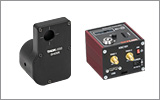
SFL1550S
ECL with SM Fiber
SFL1550P
ECL with PM Fiber


Please Wait
| Webpage Features | |
|---|---|
| Clicking this icon opens a window that contains specifications and mechanical drawings. | |
 |
Clicking this icon allows you to download our standard support documentation. |
Features
- Output Centered at 1550 nm
- External Cavity, Single-Frequency Design
- Narrow 50 kHz Typical Linewidth with 45 dB Typical SMSR
- SM or PM Fiber Output
- FC/APC Connector, 2.0 mm Narrow Key
- Industry-Standard 14-Pin, Type 1 Butterfly Package
Applications
- Seed Laser
- Laser Communications
- Metrology
- Nonlinear Frequency Doubling
- Source Laser for LIDAR/Remote Sensing Systems
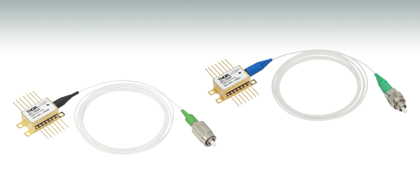
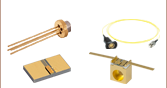
Thorlabs' External Cavity (ECL) Single-Frequency Laser Diodes deliver a narrow linewidth (50 kHz typical), single-frequency output with up to 40 mW of output power. Each external cavity, semiconductor laser is housed in a compact, 14-pin butterfly package, enabling compatibility with any standard 14-pin laser diode mount (Item # LM14S2 or LM14TS). The single-frequency laser contains an integrated thermoelectric cooler (TEC), thermistor, and optical isolator with a single mode or polarization-maintaining output fiber with an FC/APC connector. These lasers do not have built-in monitor photodiodes and must be operated in constant current mode. For constant power mode operation, please see our TO-can, pigtailed, and butterfly laser diode offerings in the selection guide to the right for options with monitor photodiodes.
These ECL lasers are compatible with Thorlabs' line of laser diode drivers and temperature controllers. These butterfly packages are also compatible with the CLD1015 laser diode mount with integrated controller and TEC. To achieve the narrowest possible linewidth, we recommend using a driver with low drive current noise, such as our LDC series of drivers. For applications requiring the most stable wavelength and power output, we recommend using the LM14TS mount due to its active stabilization of the laser diode case temperature.
While the SCLs are designed to provide high-power, single-frequency operation over a range of operating currents and temperatures, there are certain combinations where these lasers exhibit multimode operation. Proper temperature control and current tuning is needed to ensure single-frequency operation. To assist the user in selecting the appropriate operating conditions, a datasheet, which provides the operating characteristics and single-frequency regimes of that particular laser, is provided with each unit. For additional single frequency laser options, see our line of Distributed Bragg Reflector (DBR) lasers.
We recommend cleaning the fiber connector before each use if there is any chance that dust or other contaminants may have deposited on the surface. The laser intensity at the center of the fiber tip can be very high and may burn the tip of the fiber if contaminants are present. While the connectors on these pigtailed laser diodes are cleaned and capped before shipping, we cannot guarantee that they will remain free of contamination after they are removed from the package. For all of these pigtailed laser diodes, the laser must be off when connecting or disconnecting the device from other fibers, particularly when the power level is above 10 mW.
| SFL1550 Series Single-Frequency Lasers | Symbol | Min | Typical | Max |
|---|---|---|---|---|
| Center Wavelength | λC | 1549.5 nm | 1550 nm | 1550.5 nm |
| Linewidth | Δν | - | 50 kHz | 100 kHz |
| Side Mode Supression Ratio | SMSR | 40 dB | 45 dB | - |
| Optical Power @ IOP | PO | 25 mW | 40 mW | - |
| Forward Voltage @ IOP | VF | - | 1.5 V | 1.8 V |
| Operating Current | IOP | - | 300 mA | - |
| Threshold Current | ITH | - | 50 mA | - |
| Slope Efficiency | ΔP/ΔI | - | 0.2 mW/mA | - |
| Relative Intensity Noise | RIN | - | -150 dB/Hz | - |
| Single-Frequency Continuous Tuning Range (1 kHz rate) | Δf | - | 3 GHz | - |
| Operation Chip Temperature | TCHIP | - | 25 °C | - |
| Operation Case Temperature | TCASE | 10 °C | - | 60 °C |
| TEC Operation @ TCASE = 25 °C | ||||
| TEC Current | ITEC | - | 0.3 A | - |
| TEC Voltage | VTEC | - | 0.6 V | - |
| Thermistor Resistance | RTH | - | 10 kΩ | - |
The plots below are typical, and performance will vary between individual lasers. Each SFL laser diode comes with individual performance plots.
Typical Characteristics: SFL1550 Series Lasers
Click to Enlarge
Grey shaded areas indicate regions of multimode operation.
Click to Enlarge
The spectrum was measured using an optical spectrum analyzer with a spectral resolution of 0.02 nm.


Click to Enlarge
For a Lorentzian lineshape, the measured delayed self-homodyne linewidth is exactly double the laser linewidth. To obtain a Lorentzian lineshape, an ultra-low noise current driver and TEC controller must be used.
Click to Enlarge
To demonstrate single-frequency, continuous tuning, the outputs from two SFL1550 lasers were combined and the heterodyne beat frequency was measured on an RF spectrum analyzer.
ECL Single-Frequency Pigtailed Butterfly Laser Diodes Pin Diagram

| Pin Identification | |||
|---|---|---|---|
| Pin | Assignment | Pin | Assignment |
| 1 | TECa + | 14 | TEC - |
| 2 | Thermistor | 13 | Case |
| 3 | NCb | 12 | NC |
| 4 | NC | 11 | LDc Cathode |
| 5 | Thermistor | 10 | LD Anode |
| 6 | NC | 9 | NC |
| 7 | NC | 8 | NC |
ECL, DFB, VHG-Stabilized, and DBR Single-Frequency Lasers
Click to Enlarge
Figure 1: ECL Lasers have a Grating Outside of the Gain Chip
A wide variety of applications require tunable single-frequency operation of a laser system. In the world of diode lasers, there are currently four main configurations to obtain a single-frequency output: external cavity laser (ECL), distributed feedback (DFB), volume holographic grating (VHG), and distributed Bragg reflector (DBR). All four are capable of single-frequency output through the utilization of grating feedback. However, each type of laser uses a different grating feedback configuration, which influences performance characteristics such as output power, tuning range, and side mode suppression ratio (SMSR). We discuss below some of the main differences between these four types of single-frequency diode lasers.
External Cavity Laser
The External Cavity Laser (ECL) is a versatile configuration that is compatible with most standard free space diode lasers. This means that the ECL can be used at a variety of wavelengths, dependent upon the internal laser diode gain element. A lens collimates the output of the diode, which is then incident upon a grating (see Figure 1). The grating provides optical feedback and is used to select the stabilized output wavelength. With proper optical design, the external cavity allows only a single longitudinal mode to lase, providing single-frequency laser output with high side mode suppression ratio (SMSR > 45 dB).
One of the main advantages of the ECL is that the relatively long cavity provides extremely narrow linewidths (<1 MHz). Additionally, since it can incorporate a variety of laser diodes, it remains one of the few configurations that can provide narrow linewidth emission at blue or red wavelengths. The ECL can have a large tuning range (>100 nm) but is often prone to mode hops, which are very dependent on the ECL's mechanical design as well as the quality of the antireflection (AR) coating on the laser diode.
Click to Enlarge
Figure 2: DFB Lasers Have a Bragg Reflector Along the Length of the Active Gain Medium
Distributed Feedback Laser
The Distributed Feedback (DFB) Laser (available in NIR and MIR) incorporates the grating within the laser diode structure itself (see Figure 2). This corrugated periodic structure coupled closely to the active region acts as a Bragg reflector, selecting a single longitudinal mode as the lasing mode. If the active region has enough gain at frequencies near the Bragg frequency, an end reflector is unnecessary, relying instead upon the Bragg reflector for all optical feedback and mode selection. Due to this “built-in” selection, a DFB can achieve single-frequency operation over broad temperature and current ranges. To aid in mode selection and improve manufacturing yield, DFB lasers often utilize a phase shift section within the diode structure as well.
The lasing wavelength for a DFB is approximately equal to the Bragg wavelength:

where λ is the wavelength, neff is the effective refractive index, and Λ is the grating period. By changing the effective index, the lasing wavelength can be tuned. This is accomplished through temperature and current tuning of the DFB.
The DFB has a relatively narrow tuning range: about 2 nm at 850 nm, about 4 nm at 1550 nm, or at least 1 cm-1 in the mid-IR (4.00 - 11.00 µm). However, over this tuning range, the DFB can achieve single-frequency operation, which means that this is a continuous tuning range without mode hops. Because of this feature, DFBs have become a popular and majority choice for real-world applications such as telecom and sensors. Since the cavity length of a DFB is rather short, the linewidths are typically in the 1 MHz to 10 MHz range. Additionally, the close coupling between the grating structure and the active region results in lower maximum output power compared to ECL and DBR lasers.
Click to Enlarge
Figure 3: VHG Lasers have a Volume Holographic Grating Outside of the Active Gain Medium
Volume-Holographic-Grating-Stabilized Laser
A Volume-Holographic-Grating-(VHG)-Stabilized Laser also uses a Bragg reflector, but in this case a transmission grating is placed in front of the laser diode output (see Figure 3). Since the grating is not part of the laser diode structure, it can be thermally decoupled from the laser diode, improving the wavelength stability of the device. The grating typically consists of a piece of photorefractive material (typically glass) which has a periodic variation in the index of refraction. Only the wavelength of light that satisfies the Bragg condition for the grating is reflected back into the laser cavity, which results in a laser with extremely wavelength-stable emission. A VHG-Stabilized laser can produce output with a similar linewidth to a DFB laser at higher powers that is wavelength-locked over a wide range of currents and temperatures.
Click to Enlarge
Figure 4: DBR Lasers have a Bragg Reflector Outside of the Active Gain Medium
Distributed Bragg Reflector Laser
Similar to DFBs, Distributed Bragg Reflector (DBR) lasers incorporate an internal grating structure. However, whereas DFB lasers incorporate the grating structure continuously along the active region (gain region), DBR lasers place the grating structure(s) outside this region (see Figure 4). In general a DBR can incorporate various regions not typically found in a DFB that yield greater control and tuning range. For instance, a multiple-electrode DBR laser can include a phase-controlled region that allows the user to independently tune the phase apart from the grating period and laser diode current. When utilized together, the DBR can provide single-frequency operation over a broad tuning range. For example, high end sample-grating DBR lasers can have a tuning range as large as 30 - 40 nm. Unlike the DFB, the output is not mode hop free; hence, careful control of all inputs and temperature must be maintained.
In contrast to the complicated control structure for the multiple-electrode DBR, a simplified version of the DBR is engineered with just one electrode. This single-electrode DBR eliminates the complications of grating and phase control at the cost of tuning range. For this architecture type, the tuning range is similar to a DFB laser but will mode hop as a function of the applied current and temperature. Despite the disadvantage of mode hops, the single-electrode DBR does provide some advantages over its DFB cousin, namely higher output power because the grating is not continuous along the length of the device. Both DBR and DFB lasers have similar laser linewidths. Currently, Thorlabs offers only single-electrode DBR lasers.
Conclusion
ECL, DFB, VHG, and DBR laser diodes provide single-frequency operation over their designed tuning range. The ECL can be designed for a larger selection of wavelengths than either the DFB or DBR. While prone to mode hops, it also provides the narrowest linewidth (<1 MHz) of the three choices. In appropriately designed instruments, ECLs can also provide extremely broad tuning ranges (>100 nm).
The DFB laser is the most stable single-frequency, tunable laser of the four. It can provide mode-hop-free performance over its entire tuning range (<5 nm), making it one of the most popular forms of single-frequency laser for much of industry. It has the lowest output power due to inherent properties of the continuous grating feedback structure.
The VHG laser provides the most stable wavelength performance over a range of temperatures and currents and can provide higher powers than are typical in DFB lasers. This stability makes it excellent for use in OEM applications.
The single-electrode DBR laser provides similar linewidth and tuning range as the DFB (<5 nm). However, the single-electrode DBR will have periodic mode hops in its tuning curve.
Laser Safety and Classification
Safe practices and proper usage of safety equipment should be taken into consideration when operating lasers. The eye is susceptible to injury, even from very low levels of laser light. Thorlabs offers a range of laser safety accessories that can be used to reduce the risk of accidents or injuries. Laser emission in the visible and near infrared spectral ranges has the greatest potential for retinal injury, as the cornea and lens are transparent to those wavelengths, and the lens can focus the laser energy onto the retina.
 |
 |
 |
 |
 |
 |
 |
 |
 |
Safe Practices and Light Safety Accessories
- Laser safety eyewear must be worn whenever working with Class 3 or 4 lasers.
- Regardless of laser class, Thorlabs recommends the use of laser safety eyewear whenever working with laser beams with non-negligible powers, since metallic tools such as screwdrivers can accidentally redirect a beam.
- Laser goggles designed for specific wavelengths should be clearly available near laser setups to protect the wearer from unintentional laser reflections.
- Goggles are marked with the wavelength range over which protection is afforded and the minimum optical density within that range.
- Laser Safety Curtains and Laser Safety Fabric shield other parts of the lab from high energy lasers.
- Blackout Materials can prevent direct or reflected light from leaving the experimental setup area.
- Thorlabs' Enclosure Systems can be used to contain optical setups to isolate or minimize laser hazards.
- A fiber-pigtailed laser should always be turned off before connecting it to or disconnecting it from another fiber, especially when the laser is at power levels above 10 mW.
- All beams should be terminated at the edge of the table, and laboratory doors should be closed whenever a laser is in use.
- Do not place laser beams at eye level.
- Carry out experiments on an optical table such that all laser beams travel horizontally.
- Remove unnecessary reflective items such as reflective jewelry (e.g., rings, watches, etc.) while working near the beam path.
- Be aware that lenses and other optical devices may reflect a portion of the incident beam from the front or rear surface.
- Operate a laser at the minimum power necessary for any operation.
- If possible, reduce the output power of a laser during alignment procedures.
- Use beam shutters and filters to reduce the beam power.
- Post appropriate warning signs or labels near laser setups or rooms.
- Use a laser sign with a lightbox if operating Class 3R or 4 lasers (i.e., lasers requiring the use of a safety interlock).
- Do not use Laser Viewing Cards in place of a proper Beam Trap.
Laser Classification
Lasers are categorized into different classes according to their ability to cause eye and other damage. The International Electrotechnical Commission (IEC) is a global organization that prepares and publishes international standards for all electrical, electronic, and related technologies. The IEC document 60825-1 outlines the safety of laser products. A description of each class of laser is given below:
| Class | Description | Warning Label |
|---|---|---|
| 1 | This class of laser is safe under all conditions of normal use, including use with optical instruments for intrabeam viewing. Lasers in this class do not emit radiation at levels that may cause injury during normal operation, and therefore the maximum permissible exposure (MPE) cannot be exceeded. Class 1 lasers can also include enclosed, high-power lasers where exposure to the radiation is not possible without opening or shutting down the laser. |  |
| 1M | Class 1M lasers are safe except when used in conjunction with optical components such as telescopes and microscopes. Lasers belonging to this class emit large-diameter or divergent beams, and the MPE cannot normally be exceeded unless focusing or imaging optics are used to narrow the beam. However, if the beam is refocused, the hazard may be increased and the class may be changed accordingly. |  |
| 2 | Class 2 lasers, which are limited to 1 mW of visible continuous-wave radiation, are safe because the blink reflex will limit the exposure in the eye to 0.25 seconds. This category only applies to visible radiation (400 - 700 nm). |  |
| 2M | Because of the blink reflex, this class of laser is classified as safe as long as the beam is not viewed through optical instruments. This laser class also applies to larger-diameter or diverging laser beams. |  |
| 3R | Class 3R lasers produce visible and invisible light that is hazardous under direct and specular-reflection viewing conditions. Eye injuries may occur if you directly view the beam, especially when using optical instruments. Lasers in this class are considered safe as long as they are handled with restricted beam viewing. The MPE can be exceeded with this class of laser; however, this presents a low risk level to injury. Visible, continuous-wave lasers in this class are limited to 5 mW of output power. |  |
| 3B | Class 3B lasers are hazardous to the eye if exposed directly. Diffuse reflections are usually not harmful, but may be when using higher-power Class 3B lasers. Safe handling of devices in this class includes wearing protective eyewear where direct viewing of the laser beam may occur. Lasers of this class must be equipped with a key switch and a safety interlock; moreover, laser safety signs should be used, such that the laser cannot be used without the safety light turning on. Laser products with power output near the upper range of Class 3B may also cause skin burns. |  |
| 4 | This class of laser may cause damage to the skin, and also to the eye, even from the viewing of diffuse reflections. These hazards may also apply to indirect or non-specular reflections of the beam, even from apparently matte surfaces. Great care must be taken when handling these lasers. They also represent a fire risk, because they may ignite combustible material. Class 4 lasers must be equipped with a key switch and a safety interlock. |  |
| All class 2 lasers (and higher) must display, in addition to the corresponding sign above, this triangular warning sign. |  |
|
Video Insight: Setting Up a Pigtailed Butterfly Laser Diode
A laser diode packaged in a butterfly housing can be precisely controlled, in a compact package, when the laser is installed in a mount that includes thermoelectric cooler (TEC) and current drivers. The mount can make it easier, and safer, to operate the laser, but the procedure for installing the laser in the mount and configuring the settings requires some care. This video provides a step-by-step guide, which begins with an introduction to the different components and concludes with the laser operating under TEC control and with the recommended maximum current limit enabled.
When operated within their specifications, laser diodes have extremely long lifetimes. Most failures occur from mishandling or operating the lasers beyond their maximum ratings. Laser diodes are among the most static-sensitive devices currently made and proper ESD protection should be worn whenever handling a laser diode. Due to their extreme electrostatic sensitivity, laser diodes cannot be returned after their sealed package has been opened. Laser diodes in their original sealed package can be returned for a full refund or credit.
Handling and Storage Precautions
Because of their extreme susceptibility to damage from electrostatic discharge (ESD), care should be taken whenever handling and operating laser diodes.
Wrist Straps
Use grounded anti-static wrist straps whenever handling diodes.
Anti-Static Mats
Always work on grounded anti-static mats.
Laser Diode Storage
When not in use, short the leads of the laser together to protect against ESD damage.
Operating and Safety Precautions
Use an Appropriate Driver
Laser diodes require precise control of operating current and voltage to avoid overdriving the laser. In addition, the laser driver should provide protection against power supply transients. Select a laser driver appropriate for your application. Do not use a voltage supply with a current-limiting resistor since it does not provide sufficient regulation to protect the laser diode.
Power Meters
When setting up and calibrating a laser diode with its driver, use a NIST-traceable power meter to precisely measure the laser output. It is usually safest to measure the laser diode output directly before placing the laser in an optical system. If this is not possible, be sure to take all optical losses (transmissive, aperture stopping, etc.) into consideration when determining the total output of the laser.
Reflections
Flat surfaces in the optical system in front of a laser diode can cause some of the laser energy to reflect back onto the laser’s monitor photodiode, giving an erroneously high photodiode current. If optical components are moved within the system and energy is no longer reflected onto the monitor photodiode, a constant-power feedback loop will sense the drop in photodiode current and try to compensate by increasing the laser drive current and possibly overdriving the laser. Back reflections can also cause other malfunctions or damage to laser diodes. To avoid this, be sure that all surfaces are angled 5-10°, and when necessary, use optical isolators to attenuate direct feedback into the laser.
Heat Sinks
Laser diode lifetime is inversely proportional to operating temperature. Always mount the laser diode in a suitable heat sink to remove excess heat from the laser package.
Voltage and Current Overdrive
Be careful not to exceed the maximum voltage and drive current listed on the specification sheet with each laser diode, even momentarily. Also, reverse voltages as little as 3 V can damage a laser diode.
ESD-Sensitive Device
Laser diodes are susceptible to ESD damage even during operation. This is particularly aggravated by using long interface cables between the laser diode and its driver due to the inductance that the cable presents. Avoid exposing the laser diode or its mounting apparatus to ESD at all times.
ON/OFF and Power-Supply-Coupled Transients
Due to their fast response times, laser diodes can be easily damaged by transients less than 1 µs. High-current devices such as soldering irons, vacuum pumps, and fluorescent lamps can cause large momentary transients, and thus surge-protected outlets should always be used when working with laser diodes.
If you have any questions regarding laser diodes, please contact Thorlabs Technical Support for assistance.
| Posted Comments: | |
user
(posted 2022-08-06 01:32:23.327) Hi, I'm using SFL1550P. Could do you provide me with information to drive the module with ITC510&LM14S2 such as TEC current limi? I'm not sure if ITC510 is compatible with LM14S2 since the model is a little bit old. Is there any special advice for this combination? cdolbashian
(posted 2022-08-15 04:38:48.0) Thank you for reaching out to us with this inquiry! The recommended typical current needed is 300mA, the ABSOLUTE maximum is 2.8A, but I would stay around 2A as a max current limit to be safe. user
(posted 2022-03-24 14:42:11.333) We're using the SFL1550P with a CLD1015 controller. We would like to lock this laser with a similar laser using an external phase locked loop. Could the PLL tuning voltage be used to drive the CLD1015 to generate heterodyne tones with offsets determined by the PLL? My understanding is that an approx. 5 GHz single frequency tuning range is possible. ksosnowski
(posted 2022-04-20 06:16:07.0) Thanks for reaching out to Thorlabs. The SFL1550P can be continuously current-tuned to generate heterodyne beat frequencies. The manual for this unit has more detail in Sections 3.3 and 3.4, and 5GHz range is possible at a scan rate of 10Hz. Section 3.4 includes a typical frequency modulation response for the unit, showing a lower range at higher scan rates. Lawrence Trask
(posted 2021-11-09 12:30:45.357) Greetings, we are wondering if these lasers can be used as a slave laser for optical injection locking. If not, would you have any suggestions on a semiconductor laser in a butterfly package that can be used as a slave laser for optical injection locking? I did not see anything that specifies a built in isolator, but wasn’t sure if there are other things that may prevent optical injection locking using these lasers. Our wavelength of interest is at 1550 nm. YLohia
(posted 2021-11-12 03:55:22.0) Hello, thank you for contacting Thorlabs. The SFL1550P laser has not been tested in an optical injection locking application and is not intended to be used in a standard OIL scheme due to the integrated isolator. One of our Fabry-Perot laser diodes such as the FPL1009P may be a better fit, but please note that these have not been tested for such an application by Thorlabs either. Michael Thewalt
(posted 2021-04-29 17:37:55.34) We are looking for an external cavity diode laser similar to this but at 1326 nm YLohia
(posted 2021-04-30 09:59:51.0) Thank you for contacting Thorlabs. Unfortunately, we don't offer lasers like the SFL1550P at 1326 nm (or similar) at the moment. That being said, we are currently working on offering a TLX3 tunable laser for the O-band in the near-future. This will be similar to the TLX1 (https://www.thorlabs.us/newgrouppage9.cfm?objectgroup_id=9997) and will cover your 1326 nm requirement with linewidth: < 500 MHz. user
(posted 2021-04-07 01:17:30.33) Hello,
We are using SFL 1550P in a black box with variable current. I plotted current (mA) vs Power and observed that the power jumped from uW (at 62mA) to mW (63mA) and thus I took threshold current as 62mA. However, the specs says that threshold current is 50mA. Which threshold value i must take?
Please reply. YLohia
(posted 2021-04-08 10:31:14.0) Hello, thank you for contacting Thorlabs. The 50 mA listed on the website is the typical spec for threshold current. This value changes from unit to unit (and is also dependent on the operating temperature of the device). For your purposes, please use 62 mA. Samrat Sarkar
(posted 2021-03-23 14:17:21.81) Hello Yash, We are using SFL1500P with a laser diode driver and TEC controller board. When the laser is fed to a Mach Zehnder Interferometer, the interference is not stable at all, the power at both the ports of the MZI fluctuates. Please suggest us what we can do to deal with this issue and also send the phase noise, frequency noise, RIN PSDs. Also share the linewidth characteristics graph. YLohia
(posted 2021-03-30 10:44:12.0) Hello, unfortunately, we do not have phase noise, frequency noise, or RIN PSD plots for this laser. I have reached out to you directly to discuss further. YLohia
(posted 2021-04-01 11:00:13.0) Hello, thank you for contacting Thorlabs. If you're not observing interference in a well-aligned interferometer, you're either attempting to use a laser with a lower coherence length than your MZI path length or your laser is in a mode-hop (and therefore has a broader linewidth). Please try running the laser at a few different operating temperature / current combinations. For example, keep the current the same (228 mA) and then cycle the temperature down in 1 C decrements from 31 C to 25 C. If you don't see any differences in performance, try the same procedure at various other drive currents (change them in intervals of 25 mA for example). The SFL1550P can be prone to mode-hops, so if you're in a state that has one, that could explain the problem. If you have a fiber-based isolator, I would suggest plugging that in right after the laser output in case there is some instability caused by backreflections in the system.
Unfortunately, we don't have phase noise/frequency noise info. Ultimately, the final parameter (if you're only looking at the performance of the laser) that could have an impact on the interference is the linewidth (which, of course, depends on the phase noise, but it is the final easily parameter) since that affects the coherence length. user
(posted 2020-11-18 16:41:36.537) Does SFL1550S have a maximum operating current or maximum output power limit? YLohia
(posted 2020-11-18 10:22:33.0) Thank you for contacting Thorlabs. These units are serialized and individually tested. Each unit comes with its own maximum current spec. Jae Cheul Lee
(posted 2020-10-26 00:01:42.63) Hi,
Recently we bought your SFL1550P with beam collimator. I wonder you have the beam profile from the collimator output measured or expected?
Look forward to hearing from you soon. YLohia
(posted 2020-10-26 02:30:12.0) Hello, thank you for contacting Thorlabs. Which collimator did you purchase with this laser? Please note that the laser is single-mode PM pigtailed, so the fiber acts as a spatial filter producing nearly M^2 = 1 beam quality. Demian Biasetti
(posted 2019-10-24 04:31:41.95) Dear Thorlabs, we (Max Born Insitute, Germany) have recentely acquired a SFL 1550P Polarization mantaining laser diode but I can not find at any place which is the polariy that a must put in the LDC205C (Thorlabs) current controller (AG or CG). In the manual of Laser Diode Mount for 14-Pin Butterfy, where I inserted the Type I pin configiration card there is also no information about this. Another question is what does the "range" (in mA) of the single mode operation table, means. For different temperatures correspond different current and a ranges for single mode operation. Are the different current values the centers of their corresponding range (that appear in the next column of the table) to operate in single mode? in that case, I must tune the wavelenght. It is better that I do it just by changing the current an follow the linear dependence? Thank you. YLohia
(posted 2019-10-28 12:06:02.0) Hello, thank you for contacting Thorlabs. The grounding should be set to AG as shown in the "Pin Diagrams" tab of the LM14S2 mount that is intended to be used with this diode: https://www.thorlabs.com/images/TabImages/LM14S2_type1_D1-600.gif. The "Current" column in the serialized SFL specsheet is the centerpoint of the range and then the single mode range is +/- (Range/2). Supriyo Babul
(posted 2019-07-10 06:43:43.357) Dear Thorlabs,
What is the constant of thermistor(β) of the used thermistor inside SFL1550P LASER module? YLohia
(posted 2019-07-10 09:31:52.0) Hello, thank you for contacting Thorlabs. The Beta value for this thermistor is around 3870 at 25 degrees C. Alternately, the Steinhart Coefficients are:
A: 1.129241E-03;
B: 2.341077E-04;
C: 8.775468E-08; user
(posted 2019-06-11 14:32:31.68) How is this laser different from the DBR lasers (which look the same) in your product portfolio? Does the fiber pigtail contain a Bragg grating, which provides the feedback making it an external cavity laser? Or is the Bragg reflector inside the butterfly package, but not on the same chip as in DBR lasers? YLohia
(posted 2019-06-12 04:24:05.0) Hello, thank you for contacting Thorlabs. The DBR lasers have a Bragg reflector coated directly onto the gain chip, whereas the SFL series uses a separate grating mounted within the butterfly package (separated from the gain chip). We are currently in the process of releasing our Ultra Low Noise laser which will use a fiber-bragg grating to create single-frequency operation at 1550 nm. If you want more information about that, please feel free to reach us at techsupport@thorlabs.com. Xiaoguang Sun
(posted 2019-03-18 08:15:31.74) I have an SFL1550P, SN SFL 10901. I lost the measured data with the laser, can you send it to me? YLohia
(posted 2019-04-08 11:01:18.0) Hello, you can request serialized spec sheets for our laser diodes by emailing us at techsupport@thorlabs.com. We have reached out to you directly with this information. akg
(posted 2018-08-30 03:13:19.953) Dear Thorlabs,
I am looking for a Laser Diode at 1550nm. I have to operate it in CW mode without any modulation (I will use external modulation). However I need extremely narrow line-width as I intend to use in interferometry application for Quantum Key Distribution. I don't require wavelength tunability. Will SFL1550S be a good fit there and you suggest a better laser diode from Thorlabs. I am not interested in high optical power.
Sincerely,
Atul YLohia
(posted 2018-09-17 10:29:37.0) Dear Atul, thank you for contacting Thorlabs. The SFL1550S will be the best fit as a single laser diode that we currently offer. We do, however, also sell the TLX1 benchtop source which is a tunable laser that covers the 1528 - 1566nm range. The typical linewidth here is 10kHz. xhyang
(posted 2018-04-25 08:46:33.46) 带尾纤的外腔(ECL)单频激光器,蝶形封装 https://www.thorlabschina.cn/newgrouppage9.cfm?objectgroup_id=4934&pn=SFL1550P
上述产品的频率稳定性如何,如每天或每小时的频率漂移范围 YLohia
(posted 2018-05-02 08:44:40.0) Hello, thank you for contacting Thorlabs. Unfortunately, we do not have this type of reliability data outside of what is given in the manual. The stability mostly depends on the mounting and drive conditions and is generally a system-level spec. Wavelength will drift with current and, to a greater extent, with the temperature. The tuning coefficients are given in the manual. The achievable linewidth will also depend on the noise of the current source. The system should be isolated from temperature changes, vibrations, etc. for optimal performance. Timohodik
(posted 2018-02-06 09:40:46.853) Dear Thorlabs,
Could you please provide information on lifetime in hours for
SFL1550P and CLD1015? In the case of by-the-book operation, of course.
Sincerely yours,
Timophey YLohia
(posted 2018-02-26 09:10:42.0) Hello Timophey, thank you for contacting Thorlabs. While we have not performed any rigorous lifetime testing on the fully packaged laser SFL1550P, the component InP laser chip is very robust and advanced aging studies have estimated the chip lifetime at tens of years of continuous use before failure or degradation under normal operating conditions. In addition, we have had hundreds of units of SFL1550P in the field over the past several years without signs of failure or a high rates of return. Long-term performance may depend on environmental conditions. Unfortunately, we currently do not have the lifetime information/testing for CLD1015. We do, however, anticipate a high durability with this unit due to the very low percentage of RMAs processed since the release of this item in 2012. bsvikram
(posted 2017-05-23 01:10:11.363) Hi, We wanted to know the highest frequency at which SFL1550S can be current modulated and whether this can be done with CLD 1015 mount. We would like to modulate the current at least at few MHz. nbayconich
(posted 2017-06-16 08:13:21.0) Thank you for contacting Thorlabs. The SFL1550S ECL laser diode can be directly modulated up to 10 Mhz but the CLD1015 can only directly modulate a butterfly laser diode package up to 250Khz at 3 dB. Modulating at high frequencies can change the frequency spectrum of the diode but a few Mhz should not change the spectrum.
Another way to modulate the SFL1550S ECL is to use an external modulator. A Techsupport representative will contact you directly with more information. kkmion
(posted 2016-09-16 17:07:39.433) can you supply the Pigtailed External Cavity (ECL) Single-Frequency Lasers at wavelength of 1064 nm? jlow
(posted 2016-09-20 02:22:59.0) Response from Jeremy at Thorlabs: I will contact you directly to discuss about this quote. zsolt.kis1
(posted 2015-09-08 06:17:48.063) Dear Thorlabs,
I would like to use the SFL1150P diode laser in a pulsed mode with an appropriate driver. The driver I would use is capable to modulate the laser current up to 50MHz. My idea is to modulate the laser current between just below the laser threshold and at some current above the threshold, hence I want to create pulses in this way. The pulse width is supposed to be 100-200 ns. What is the response of your laser to such driving ?
Best Regards,
Zsolt Kis
HAS Wigner RCP jlow
(posted 2015-09-18 11:11:19.0) Response from Jeremy at Thorlabs: We have a section in the manual (Section 3.4) discussing about the frequency modulation bandwidth. We will contact you directly to provide more information on this. matthias
(posted 2014-10-15 19:29:21.68) Hi. Can you produce a version of the SFL1550P with a center wavelength of 1560 nm? jlow
(posted 2014-10-16 01:30:24.0) Response from Jeremy at Thorlabs: We can quote this and we will contact you directly for the quote. You can also send RFQ to techsupport@thorlabs.com. pejr
(posted 2014-08-14 16:28:01.177) Hi. Is the Thorlabs' External Cavity (ECL) Single-Frequency Laser Diode at a custom wavelength of 780.0 nm or 785.0 nm possible? Linewidth of <100 kHz to 500 kHz (@10 millisecond measurement time) is also required. Desired output power >35 mW. jlow
(posted 2014-08-19 11:36:13.0) Response from Jeremy at Thorlabs: We do not have the SFL for 780nm range in a butterfly package at the moment. We do have the TLK-L780M which might be suitable for your application. We will contact directly to discuss about this. hallt
(posted 2013-08-07 12:59:58.073) Hi. I would like a very very low intensity noise laser. I was thinking of using your SFL1550S with the CLD1015 controller as you suggest. Could you give me an idea of how much noise I could expect over a 100 kHz-100 MHz using this configuration? thanks. tschalk
(posted 2013-08-09 07:57:00.0) This is a response from Thomas at Thorlabs. Thank you very much for your inquiry. We specify the noise and ripple of the CLD1015 with 30µA without noise reduction filter and 15µA with noise reduction filter (10Hz to 10MHz, RMS). A better solution for low noise applications would be an LDC2xxC, which can be found here: https://www.thorlabs.com/newgrouppage9.cfm?objectgroup_id=10. The LDC205C, for example, delivers 500mA laser current and the noise without ripple is <3µA (10Hz to 10MHz, RMS) and the ripple is <2µA (50/60Hz, RMS). I will contact you with more detailed information. |
| The rows shaded green below denote single-frequency lasers. |
| Item # | Wavelength | Output Power | Operating Current | Operating Voltage | Beam Divergence | Laser Mode | Package | |
|---|---|---|---|---|---|---|---|---|
| Parallel | Perpendicular | |||||||
| L375P70MLD | 375 nm | 70 mW | 110 mA | 5.4 V | 9° | 22.5° | Single Transverse Mode | Ø5.6 mm |
| L404P400M | 404 nm | 400 mW | 370 mA | 4.9 V | 13° (1/e2) | 42° (1/e2) | Multimode | Ø5.6 mm |
| LP405-SF10 | 405 nm | 10 mW | 50 mA | 5.0 V | - | - | Single Transverse Mode | Ø5.6 mm, SM Pigtail |
| L405P20 | 405 nm | 20 mW | 38 mA | 4.8 V | 8.5° | 19° | Single Transverse Mode | Ø5.6 mm |
| LP405C1 | 405 nm | 30 mW | 75 mA | 4.3 V | 1.4 mrad | 1.4 mrad | Single Transverse Mode | Ø3.8 mm, SM Pigtail with Collimator |
| L405G2 | 405 nm | 35 mW | 50 mA | 4.9 V | 10° | 21° | Single Transverse Mode | Ø3.8 mm |
| DL5146-101S | 405 nm | 40 mW | 70 mA | 5.2 V | 8° | 19° | Single Transverse Mode | Ø5.6 mm |
| L405A1 | 405 nm | 175 mW (Min) | 150 mA | 5.0 V | 9° | 20° | Single Transverse Mode | Ø5.6 mm |
| LP405-MF300 | 405 nm | 300 mW | 350 mA | 4.5 V | - | - | Multimode | Ø5.6 mm, MM Pigtail |
| L405G1 | 405 nm | 1000 mW | 900 mA | 5.0 V | 13° | 45° | Multimode | Ø9 mm |
| LP450-SF25 | 450 nm | 25 mW | 75 mA | 5.0 V | - | - | Single Transverse Mode | Ø5.6 mm, SM Pigtail |
| L450G3 | 450 nm | 100 mW (Min) | 80 mA | 5.2 V | 8.4° | 21.5° | Single Transverse Mode | Ø3.8 mm |
| L450G2 | 450 nm | 100 mW (Min) | 80 mA | 5.0 V | 8.4° | 21.5° | Single Transverse Mode | Ø5.6 mm |
| L450P1600MM | 450 nm | 1600 mW | 1200 mA | 4.8 V | 7° | 19 - 27° | Multimode | Ø5.6 mm |
| L473P100 | 473 nm | 100 mW | 120 mA | 5.7 V | 10 | 24 | Single Transverse Mode | Ø5.6 mm |
| LP488-SF20 | 488 nm | 20 mW | 70 mA | 6.0 V | - | - | Single Transverse Mode | Ø5.6 mm, SM Pigtail |
| LP488-SF20G | 488 nm | 20 mW | 80 mA | 5.5 V | - | - | Single Transverse Mode | Ø5.6 mm, SM Pigtail |
| L488P60 | 488 nm | 60 mW | 75 mA | 6.8 V | 7° | 23° | Single Transverse Mode | Ø5.6 mm |
| LP515-SF3 | 515 nm | 3 mW | 50 mA | 5.3 V | - | - | Single Transverse Mode | Ø5.6 mm, SM Pigtail |
| L515A1 | 515 nm | 10 mW | 50 mA | 5.4 V | 6.5° | 21° | Single Transverse Mode | Ø5.6 mm |
| LP520-SF15A | 520 nm | 15 mW | 100 mA | 7.0 V | - | - | Single Transverse Mode | Ø5.6 mm, SM Pigtail |
| LP520-SF15 | 520 nm | 15 mW | 140 mA | 6.5 V | - | - | Single Transverse Mode | Ø9 mm, SM Pigtail |
| L520A1 | 520 nm | 30 mW (Min) | 80 mA | 5.5 V | 8° | 22° | Single Transverse Mode | Ø5.6 mm |
| PL520 | 520 nm | 50 mW | 250 mA | 7.0 V | 7° | 22° | Single Transverse Mode | Ø3.8 mm |
| L520P50 | 520 nm | 45 mW | 150 mA | 7.0 V | 7° | 22° | Single Transverse Mode | Ø5.6 mm |
| L520A2 | 520 nm | 110 mW (Min) | 225 mA | 5.9 V | 8° | 22° | Single Transverse Mode | Ø5.6 mm |
| DJ532-10 | 532 nm | 10 mW | 220 mA | 1.9 V | 0.69° | 0.69° | Single Transverse Mode | Ø9.5 mm (non-standard) |
| DJ532-40 | 532 nm | 40 mW | 330 mA | 1.9 V | 0.69° | 0.69° | Single Transverse Mode | Ø9.5 mm (non-standard) |
| LP633-SF50 | 633 nm | 50 mW | 170 mA | 2.6 V | - | - | Single Transverse Mode | Ø5.6 mm, SM Pigtail |
| HL63163DG | 633 nm | 100 mW | 170 mA | 2.6 V | 8.5° | 18° | Single Transverse Mode | Ø5.6 mm |
| LPS-635-FC | 635 nm | 2.5 mW | 70 mA | 2.2 V | - | - | Single Transverse Mode | Ø9 mm, SM Pigtail |
| LPS-PM635-FC | 635 nm | 2.5 mW | 60 mA | 2.2 V | - | - | Single Transverse Mode | Ø9.0 mm, PM Pigtail |
| L635P5 | 635 nm | 5 mW | 30 mA | <2.7 V | 8° | 32° | Single Transverse Mode | Ø5.6 mm |
| HL6312G | 635 nm | 5 mW | 50 mA | <2.7 V | 8° | 31° | Single Transverse Mode | Ø9 mm |
| LPM-635-SMA | 635 nm | 8 mW | 50 mA | 2.2 V | - | - | Multimode | Ø9 mm, MM Pigtail |
| LP635-SF8 | 635 nm | 8 mW | 60 mA | 2.3 V | - | - | Single Transverse Mode | Ø5.6 mm, SM Pigtail |
| HL6320G | 635 nm | 10 mW | 60 mA | 2.2 V | 8° | 31° | Single Transverse Mode | Ø9 mm |
| HL6322G | 635 nm | 15 mW | 75 mA | 2.4 V | 8° | 30° | Single Transverse Mode | Ø9 mm |
| L637P5 | 637 nm | 5 mW | 20 mA | <2.4 V | 8° | 34° | Single Transverse Mode | Ø5.6 mm |
| LP637-SF50 | 637 nm | 50 mW | 140 mA | 2.6 V | - | - | Single Transverse Mode | Ø5.6 mm, SM Pigtail |
| LP637-SF70 | 637 nm | 70 mW | 220 mA | 2.7 V | - | - | Single Transverse Mode | Ø5.6 mm, SM Pigtail |
| HL63142DG | 637 nm | 100 mW | 140 mA | 2.7 V | 8° | 18° | Single Transverse Mode | Ø5.6 mm |
| HL63133DG | 637 nm | 170 mW | 250 mA | 2.8 V | 9° | 17° | Single Transverse Mode | Ø5.6 mm |
| HL6388MG | 637 nm | 250 mW | 340 mA | 2.3 V | 10° | 40° | Multimode | Ø5.6 mm |
| L637G1 | 637 nm | 1200 mW | 1100 mA | 2.5 V | 10° | 32° | Multimode | Ø9 mm (non-standard) |
| L638P040 | 638 nm | 40 mW | 92 mA | 2.4 V | 10° | 21° | Single Transverse Mode | Ø5.6 mm |
| L638P150 | 638 nm | 150 mW | 230 mA | 2.7 V | 9 | 18 | Single Transverse Mode | Ø3.8 mm |
| L638P200 | 638 nm | 200 mW | 280 mA | 2.9 V | 8 | 14 | Single Transverse Mode | Ø5.6 mm |
| L638P700M | 638 nm | 700 mW | 820 mA | 2.2 V | 9° | 35° | Multimode | Ø5.6 mm |
| HL6358MG | 639 nm | 10 mW | 40 mA | 2.4 V | 8° | 21° | Single Transverse Mode | Ø5.6 mm |
| HL6323MG | 639 nm | 30 mW | 100 mA | 2.5 V | 8.5° | 30° | Single Transverse Mode | Ø5.6 mm |
| HL6362MG | 640 nm | 40 mW | 90 mA | 2.5 V | 10° | 21° | Single Transverse Mode | Ø5.6 mm |
| LP642-SF20 | 642 nm | 20 mW | 90 mA | 2.5 V | - | - | Single Transverse Mode | Ø5.6 mm, SM Pigtail |
| LP642-PF20 | 642 nm | 20 mW | 110 mA | 2.5 V | - | - | Single Transverse Mode | Ø5.6 mm, PM Pigtail |
| HL6364DG | 642 nm | 60 mW | 120 mA | 2.5 V | 10° | 21° | Single Transverse Mode | Ø5.6 mm |
| HL6366DG | 642 nm | 80 mW | 150 mA | 2.5 V | 10° | 21° | Single Transverse Mode | Ø5.6 mm |
| HL6385DG | 642 nm | 150 mW | 250 mA | 2.6 V | 9° | 17° | Single Transverse Mode | Ø5.6 mm |
| L650P007 | 650 nm | 7 mW | 28 mA | 2.2 V | 9° | 28° | Single Transverse Mode | Ø5.6 mm |
| LPS-660-FC | 658 nm | 7.5 mW | 65 mA | 2.6 V | - | - | Single Transverse Mode | Ø5.6 mm, SM Pigtail |
| LP660-SF20 | 658 nm | 20 mW | 80 mA | 2.6 V | - | - | Single Transverse Mode | Ø5.6 mm, SM Pigtail |
| LPM-660-SMA | 658 nm | 22.5 mW | 65 mA | 2.6 V | - | - | Multimode | Ø5.6 mm, MM Pigtail |
| HL6501MG | 658 nm | 30 mW | 75 mA | 2.6 V | 8.5° | 22° | Single Transverse Mode | Ø5.6 mm |
| L658P040 | 658 nm | 40 mW | 75 mA | 2.2 V | 10° | 20° | Single Transverse Mode | Ø5.6 mm |
| LP660-SF40 | 658 nm | 40 mW | 135 mA | 2.5 V | - | - | Single Transverse Mode | Ø5.6 mm, SM Pigtail |
| LP660-SF60 | 658 nm | 60 mW | 210 mA | 2.4 V | - | - | Single Transverse Mode | Ø5.6 mm, SM Pigtail |
| HL6544FM | 660 nm | 50 mW | 115 mA | 2.3 V | 10° | 17° | Single Transverse Mode | Ø5.6 mm |
| LP660-SF50 | 660 nm | 50 mW | 140 mA | 2.3 V | - | - | Single Transverse Mode | Ø5.6 mm, SM Pigtail |
| HL6545MG | 660 nm | 120 mW | 170 mA | 2.45 V | 10° | 17° | Single Transverse Mode | Ø5.6 mm |
| L660P120 | 660 nm | 120 mW | 175 mA | 2.5 V | 10° | 17° | Single Transverse Mode | Ø5.6 mm |
| L670VH1 | 670 nm | 1 mW | 2.5 mA | 2.6 V | 10° | 10° | Single Transverse Mode | TO-46 |
| LPS-675-FC | 670 nm | 2.5 mW | 55 mA | 2.2 V | - | - | Single Transverse Mode | Ø9 mm, SM Pigtail |
| HL6748MG | 670 nm | 10 mW | 30 mA | 2.2 V | 8° | 25° | Single Transverse Mode | Ø5.6 mm |
| HL6714G | 670 nm | 10 mW | 55 mA | <2.7 V | 8° | 22° | Single Transverse Mode | Ø9 mm |
| HL6756MG | 670 nm | 15 mW | 35 mA | 2.3 V | 8° | 24° | Single Transverse Mode | Ø5.6 mm |
| LP685-SF15 | 685 nm | 15 mW | 55 mA | 2.1 V | - | - | Single Transverse Mode | Ø5.6 mm, SM Pigtail |
| HL6750MG | 685 nm | 50 mW | 70 mA | 2.3 V | 9° | 21° | Single Transverse Mode | Ø5.6 mm |
| HL6738MG | 690 nm | 30 mW | 85 mA | 2.5 V | 8.5° | 19° | Single Transverse Mode | Ø5.6 mm |
| LP705-SF15 | 705 nm | 15 mW | 55 mA | 2.3 V | - | - | Single Transverse Mode | Ø5.6 mm, SM Pigtail |
| HL7001MG | 705 nm | 40 mW | 75 mA | 2.5 V | 9° | 18° | Single Transverse Mode | Ø5.6 mm |
| LP730-SF15 | 730 nm | 15 mW | 70 mA | 2.5 V | - | - | Single Transverse Mode | Ø5.6 mm, SM Pigtail |
| HL7302MG | 730 nm | 40 mW | 75 mA | 2.5 V | 9° | 18° | Single Transverse Mode | Ø5.6 mm |
| L760VH1 | 760 nm | 0.5 mW | 3 mA (Max) | 2.2 V | 12° | 12° | Single Frequency | TO-46 |
| DBR760PN | 761 nm | 9 mW | 125 mA | 2.0 V | - | - | Single Frequency | Butterfly, PM Pigtail |
| L763VH1 | 763 nm | 0.5 mW | 3 mA (Max) | 2.0 V | 10° | 10° | Single Frequency | TO-46 |
| DBR767PN | 767 nm | 23 mW | 220 mA | 1.87 V | - | - | Single Frequency | Butterfly, PM Pigtail |
| DBR770PN | 770 nm | 35 mW | 220 mA | 1.92 V | - | - | Single Frequency | Butterfly, PM Pigtail |
| L780P010 | 780 nm | 10 mW | 24 mA | 1.8 V | 8° | 30° | Single Transverse Mode | Ø5.6 mm |
| DBR780PN | 780 nm | 45 mW | 250 mA | 1.9 V | - | - | Single Frequency | Butterfly, PM Pigtail |
| L785P5 | 785 nm | 5 mW | 28 mA | 1.9 V | 10° | 29° | Single Transverse Mode | Ø5.6 mm |
| LPS-PM785-FC | 785 nm | 6.5 mW | 60 mA | - | - | - | Single Transverse Mode | Ø5.6 mm, PM Pigtail |
| LPS-785-FC | 785 nm | 10 mW | 65 mA | 1.85 V | - | - | Single Transverse Mode | Ø5.6 mm, SM Pigtail |
| LP785-SF20 | 785 nm | 20 mW | 85 mA | 1.9 V | - | - | Single Transverse Mode | Ø5.6 mm, SM Pigtail |
| DBR785S | 785 nm | 25 mW | 230 mA | 2.0 V | - | - | Single Frequency | Butterfly, SM Pigtail |
| DBR785P | 785 nm | 25 mW | 230 mA | 2.0 V | - | - | Single Frequency | Butterfly, PM Pigtail |
| L785P25 | 785 nm | 25 mW | 45 mA | 1.9 V | 8° | 30° | Single Transverse Mode | Ø5.6 mm |
| FPV785S | 785 nm | 50 mW | 410 mA | 2.2 V | - | - | Single Frequency | Butterfly, SM Pigtail |
| FPV785P | 785 nm | 50 mW | 410 mA | 2.1 V | - | - | Single Frequency | Butterfly, PM Pigtail |
| LP785-SAV50 | 785 nm | 50 mW | 500 mA | 2.2 V | - | - | Single Frequency | Ø9 mm, SM Pigtail |
| L785P090 | 785 nm | 90 mW | 125 mA | 2.0 V | 10° | 17° | Single Transverse Mode | Ø5.6 mm |
| LP785-SF100 | 785 nm | 100 mW | 300 mA | 2.0 V | - | - | Single Transverse Mode | Ø9 mm, SM Pigtail |
| FPL785P | 785 nm | 200 mW | 500 mA | 2.1 V | - | - | Single Transverse Mode | Butterfly, PM Pigtail |
| FPL785S-250 | 785 nm | 250 mW (Min) | 500 mA | 2.0 V | - | - | Single Transverse Mode | Butterfly, SM Pigtail |
| LD785-SEV300 | 785 nm | 300 mW | 500 mA (Max) | 2.0 V | 8° | 16° | Single Frequency | Ø9 mm |
| LD785-SH300 | 785 nm | 300 mW | 400 mA | 2.0 V | 7° | 18° | Single Transverse Mode | Ø9 mm |
| FPL785C | 785 nm | 300 mW | 400 mA | 2.0 V | 7° | 18° | Single Transverse Mode | 3 mm x 5 mm Submount |
| LD785-SE400 | 785 nm | 400 mW | 550 mA | 2.0 V | 7° | 16° | Single Transverse Mode | Ø9 mm |
| FPV785M | 785 nm | 600 mW | 1100 mA | 1.9 V | - | - | Multimode | Butterfly, MM Pigtail |
| L795VH1 | 795 nm | 0.25 mW | 1.2 mA | 1.8 V | 20° | 12° | Single Frequency | TO-46 |
| DBR795PN | 795 nm | 40 mW | 230 mA | 2.0 V | - | - | Single Frequency | Butterfly, PM Pigtail |
| DBR808PN | 808 nm | 42 mW | 250 mA | 2 V | - | - | Single Frequency | Butterfly, PM Pigtail |
| LP808-SA60 | 808 nm | 60 mW | 150 mA | 1.9 V | - | - | Single Transverse Mode | Ø9 mm, SM Pigtail |
| M9-808-0150 | 808 nm | 150 mW | 180 mA | 1.9 V | 8° | 17° | Single Transverse Mode | Ø9 mm |
| L808P200 | 808 nm | 200 mW | 260 mA | 2 V | 10° | 30° | Multimode | Ø5.6 mm |
| FPL808P | 808 nm | 200 mW | 600 mA | 2.1 V | - | - | Single Transverse Mode | Butterfly, PM Pigtail |
| FPL808S | 808 nm | 200 mW | 750 mA | 2.3 V | - | - | Single Transverse Mode | Butterfly, SM Pigtail |
| L808H1 | 808 nm | 300 mW | 400 mA | 2.1 V | 14° | 6° | Single Transverse Mode | Ø9 mm |
| LD808-SE500 | 808 nm | 500 mW | 750 mA | 2.2 V | 7° | 14° | Single Transverse Mode | Ø9 mm |
| LD808-SEV500 | 808 nm | 500 mW | 800 mA (Max) | 2.2 V | 8° | 14° | Single Frequency | Ø9 mm |
| L808P500MM | 808 nm | 500 mW | 650 mA | 1.8 V | 12° | 30° | Multimode | Ø5.6 mm |
| L808P1000MM | 808 nm | 1000 mW | 1100 mA | 2 V | 9° | 30° | Multimode | Ø9 mm |
| DBR816PN | 816 nm | 45 mW | 250 mA | 1.95 V | - | - | Single Frequency | Butterfly, PM Pigtail |
| LP820-SF80 | 820 nm | 80 mW | 230 mA | 2.3 V | - | - | Single Transverse Mode | Ø5.6 mm, SM Pigtail |
| L820P100 | 820 nm | 100 mW | 145 mA | 2.1 V | 9° | 17° | Single Transverse Mode | Ø5.6 mm |
| L820P200 | 820 nm | 200 mW | 250 mA | 2.4 V | 9° | 17° | Single Transverse Mode | Ø5.6 mm |
| DBR828PN | 828 nm | 24 mW | 250 mA | 2.0 V | - | - | Single Frequency | Butterfly, PM Pigtail |
| LPS-830-FC | 830 nm | 10 mW | 120 mA | - | - | - | Single Transverse Mode | Ø5.6 mm, SM Pigtail |
| LPS-PM830-FC | 830 nm | 10 mW | 50 mA | 2.0 V | - | - | Single Transverse Mode | Ø5.6 mm, PM Pigtail |
| LP830-SF30 | 830 nm | 30 mW | 115 mA | 1.9 V | - | - | Single Transverse Mode | Ø9 mm, SM Pigtail |
| HL8338MG | 830 nm | 50 mW | 75 mA | 1.9 V | 9° | 22° | Single Transverse Mode | Ø5.6 mm |
| L830H1 | 830 nm | 250 mW | 3 A (Max) | 2 V | 8° | 10° | Single Transverse Mode | Ø9 mm |
| FPL830P | 830 nm | 300 mW | 900 mA | 2.22 V | - | - | Single Transverse Mode | Butterfly, PM Pigtail |
| FPL830S | 830 nm | 350 mW | 900 mA | 2.5 V | - | - | Single Transverse Mode | Butterfly, SM Pigtail |
| LD830-SE650 | 830 nm | 650 mW | 900 mA | 2.3 V | 7° | 13° | Single Transverse Mode | Ø9 mm |
| LD830-MA1W | 830 nm | 1 W | 2 A | 2.1 V | 7° | 24° | Multimode | Ø9 mm |
| LD830-ME2W | 830 nm | 2 W | 3 A (Max) | 2.0 V | 8° | 21° | Multimode | Ø9 mm |
| L840P200 | 840 nm | 200 mW | 255 mA | 2.4 V | 9 | 17 | Single Transverse Mode | Ø5.6 mm |
| L850VH1 | 850 nm | 1 mW | 6 mA (Max) | 2 V | 12° | 12° | Single Frequency | TO-46 |
| L850P010 | 850 nm | 10 mW | 50 mA | 2 V | 10° | 30° | Single Transverse Mode | Ø5.6 mm |
| L850P030 | 850 nm | 30 mW | 65 mA | 2 V | 8.5° | 30° | Single Transverse Mode | Ø5.6 mm |
| FPV852S | 852 nm | 20 mW | 400 mA | 2.2 V | - | - | Single Frequency | Butterfly, SM Pigtail |
| FPV852P | 852 nm | 20 mW | 400 mA | 2.2 V | - | - | Single Frequency | Butterfly, PM Pigtail |
| DBR852PN | 852 nm | 24 mW | 300 mA | 2.0 V | - | - | Single Frequency | Butterfly, PM Pigtail |
| LP852-SF30 | 852 nm | 30 mW | 115 mA | 1.9 V | - | - | Single Transverse Mode | Ø9 mm, SM Pigtail |
| L852P50 | 852 nm | 50 mW | 75 mA | 1.9 V | 9° | 22° | Single Transverse Mode | Ø5.6 mm |
| LP852-SF60 | 852 nm | 60 mW | 150 mA | 2.0 V | - | - | Single Transverse Mode | Ø9 mm, SM Pigtail |
| L852P100 | 852 nm | 100 mW | 120 mA | 1.9 V | 8° | 28° | Single Transverse Mode | Ø9 mm |
| L852P150 | 852 nm | 150 mW | 170 mA | 1.9 V | 8° | 18° | Single Transverse Mode | Ø9 mm |
| L852SEV1 | 852 nm | 270 mW | 400 mA (Max) | 2.0 V | 9° | 12° | Single Frequency | Ø9 mm |
| L852H1 | 852 nm | 300 mW | 415 mA (Max) | 2 V | 7° | 15° | Single Transverse Mode | Ø9 mm |
| FPL852P | 852 nm | 300 mW | 900 mA | 2.35 V | - | - | Single Transverse Mode | Butterfly, PM Pigtail |
| FPL852S | 852 nm | 350 mW | 900 mA | 2.5 V | - | - | Single Transverse Mode | Butterfly, SM Pigtail |
| LD852-SE600 | 852 nm | 600 mW | 950 mA | 2.3 V | 7° (1/e2) | 13° (1/e2) | Single Transverse Mode | Ø9 mm |
| LD852-SEV600 | 852 nm | 600 mW | 1050 mA (Max) | 2.2 V | 8° | 13° (1/e2) | Single Frequency | Ø9 mm |
| LP880-SF3 | 880 nm | 3 mW | 25 mA | 2.2 V | - | - | Single Transverse Mode | Ø5.6 mm, SM Pigtail |
| L880P010 | 880 nm | 10 mW | 30 mA | 2.0 V | 12° | 37° | Single Transverse Mode | Ø5.6 mm |
| L895VH1 | 895 nm | 0.2 mW | 1.4 mA | 1.6 V | 20° | 13° | Single Frequency | TO-46 |
| DBR895PN | 895 nm | 12 mW | 300 mA | 2 V | - | - | Single Frequency | Butterfly, PM Pigtail |
| LP904-SF3 | 904 nm | 3 mW | 30 mA | 1.5 V | - | - | Single Transverse Mode | Ø5.6 mm, SM Pigtail |
| L904P010 | 904 nm | 10 mW | 50 mA | 2.0 V | 10° | 30° | Single Transverse Mode | Ø5.6 mm |
| LP915-SF40 | 915 nm | 40 mW | 130 mA | 1.5 V | - | - | Single Transverse Mode | Ø9 mm, SM Pigtail |
| DBR935PN | 935 nm | 13 mW | 300 mA | 1.75 V | - | - | Single Frequency | Butterfly, PM Pigtail |
| LP940-SF30 | 940 nm | 30 mW | 90 mA | 1.5 V | - | - | Single Transverse Mode | Ø9 mm, SM Pigtail |
| M9-940-0200 | 940 nm | 200 mW | 270 mA | 1.9 V | 8° | 28° | Single Transverse Mode | Ø9 mm |
| L960H1 | 960 nm | 250 mW | 400 mA | 2.1 V | 11° | 12° | Single Transverse Mode | Ø9 mm |
| FPV976S | 976 nm | 30 mW | 400 mA (Max) | 2.2 V | - | - | Single Frequency | Butterfly, SM Pigtail |
| FPV976P | 976 nm | 30 mW | 400 mA (Max) | 2.2 V | - | - | Single Frequency | Butterfly, PM Pigtail |
| DBR976PN | 976 nm | 33 mW | 450 mA | 2.0 V | - | - | Single Frequency | Butterfly, PM Pigtail |
| L976SEV1 | 976 nm | 270 mW | 400 mA (Max) | 2.0 V | 9° | 12° | Single Frequency | Ø9 mm |
| BL976-SAG3 | 976 nm | 300 mW | 470 mA | 2.0 V | - | - | Single Transverse Mode | Butterfly, SM Pigtail |
| BL976-PAG500 | 976 nm | 500 mW | 830 mA | 2.0 V | - | - | Single Transverse Mode | Butterfly, PM Pigtail |
| BL976-PAG700 | 976 nm | 700 mW | 1090 mA | 2.0 V | - | - | Single Transverse Mode | Butterfly, PM Pigtail |
| BL976-PAG900 | 976 nm | 900 mW | 1480 mA | 2.5 V | - | - | Single Transverse Mode | Butterfly, PM Pigtail |
| L980P010 | 980 nm | 10 mW | 25 mA | 2 V | 10° | 30° | Single Transverse Mode | Ø5.6 mm |
| LP980-SF15 | 980 nm | 15 mW | 70 mA | 1.5 V | - | - | Single Transverse Mode | Ø5.6 mm, SM Pigtail |
| L980P030 | 980 nm | 30 mW | 50 mA | 1.5 V | 10° | 35° | Single Transverse Mode | Ø5.6 mm |
| L980P100A | 980 nm | 100 mW | 150 mA | 1.6 V | 6° | 32° | Multimode | Ø5.6 mm |
| LP980-SA60 | 980 nm | 60 mW | 230 mA | 2.0 V | - | - | Single Transverse Mode | Ø9.0 mm, SM Pigtail |
| L980H1 | 980 nm | 200 mW | 300 mA (Max) | 2.0 V | 8° | 13° | Single Transverse Mode | Ø9 mm |
| L980P200 | 980 nm | 200 mW | 300 mA | 1.5 V | 6° | 30° | Multimode | Ø5.6 mm |
| DBR1060SN | 1060 nm | 130 mW | 650 mA | 2.0 V | - | - | Single Frequency | Butterfly, SM Pigtail |
| DBR1060PN | 1060 nm | 130 mW | 650 mA | 1.8 V | - | - | Single Frequency | Butterfly, PM Pigtail |
| DBR1064S | 1064 nm | 40 mW | 150 mA | 2.0 V | - | - | Single Frequency | Butterfly, SM Pigtail |
| DBR1064P | 1064 nm | 40 mW | 150 mA | 2.0 V | - | - | Single Frequency | Butterfly, PM Pigtail |
| DBR1064PN | 1064 nm | 110 mW | 550 mA | 2.0 V | - | - | Single Frequency | Butterfly, PM Pigtail |
| LPS-1060-FC | 1064 nm | 50 mW | 220 mA | 1.4 V | - | - | Single Transverse Mode | Ø9 mm, SM Pigtail |
| M9-A64-0200 | 1064 nm | 200 mW | 280 mA | 1.7 V | 8° | 28° | Single Transverse Mode | Ø9 mm |
| L1064H1 | 1064 nm | 300 mW | 700 mA | 1.92 V | 7.6° | 13.5° | Single Transverse Mode | Ø9 mm |
| L1064H2 | 1064 nm | 450 mW | 1100 mA | 1.92 V | 7.6° | 13.5° | Single Transverse Mode | Ø9 mm |
| DBR1083PN | 1083 nm | 100 mW | 500 mA | 1.75 V | - | - | Single Frequency | Butterfly, PM Pigtail |
| L1270P5DFB | 1270 nm | 5 mW | 15 mA | 1.1 V | 7° | 9° | Single Frequency | Ø5.6 mm |
| L1290P5DFB | 1290 nm | 5 mW | 16 mA | 1.0 V | 7° | 9° | Single Frequency | Ø5.6 mm |
| LP1310-SAD2 | 1310 nm | 2.0 mW | 40 mA | 1.1 V | - | - | Single Frequency | Ø5.6 mm, SM Pigtail |
| LP1310-PAD2 | 1310 nm | 2.0 mW | 40 mA | 1.0 V | - | - | Single Frequency | Ø5.6 mm, PM Pigtail |
| LPS-PM1310-FC | 1310 nm | 2.5 mW | 20 mA | 1.1 V | - | - | Single Transverse Mode | Ø5.6 mm, PM Pigtail |
| L1310P5DFB | 1310 nm | 5 mW | 16 mA | 1.0 V | 7° | 9° | Single Frequency | Ø5.6 mm |
| ML725B8F | 1310 nm | 5 mW | 20 mA | 1.1 V | 25° | 30° | Single Transverse Mode | Ø5.6 mm |
| LPSC-1310-FC | 1310 nm | 50 mW | 350 mA | 2 V | - | - | Single Transverse Mode | Ø5.6 mm, SM Pigtail |
| FPL1053S | 1310 nm | 130 mW | 400 mA | 1.7 V | - | - | Single Transverse Mode | Butterfly, SM Pigtail |
| FPL1053P | 1310 nm | 130 mW | 400 mA | 1.7 V | - | - | Single Transverse Mode | Butterfly, PM Pigtail |
| FPL1053T | 1310 nm | 300 mW (Pulsed) | 750 mA | 2 V | 15° | 28° | Single Transverse Mode | Ø5.6 mm |
| FPL1053C | 1310 nm | 300 mW (Pulsed) | 750 mA | 2 V | 15° | 27° | Single Transverse Mode | Chip on Submount |
| L1310G1 | 1310 nm | 2000 mW | 5 A | 1.5 V | 7° | 24° | Multimode | Ø9 mm |
| L1330P5DFB | 1330 nm | 5 mW | 14 mA | 1.0 V | 7° | 9° | Single Frequency | Ø5.6 mm |
| L1370G1 | 1370 nm | 2000 mW | 5 A | 1.4 V | 6° | 22° | Multimode | Ø9 mm |
| BL1425-PAG500 | 1425 nm | 500 mW | 1600 mA | 2.0 V | - | - | Single Transverse Mode | Butterfly, PM Pigtail |
| BL1436-PAG500 | 1436 nm | 500 mW | 1600 mA | 2.0 V | - | - | Single Transverse Mode | Butterfly, PM Pigtail |
| L1450G1 | 1450 nm | 2000 mW | 5 A | 1.4 V | 7° | 22° | Multimode | Ø9 mm |
| BL1456-PAG500 | 1456 nm | 500 mW | 1600 mA | 2.0 V | - | - | Single Transverse Mode | Butterfly, PM Pigtail |
| L1470P5DFB | 1470 nm | 5 mW | 19 mA | 1.0 V | 7° | 9° | Single Frequency | Ø5.6 mm |
| L1480G1 | 1480 nm | 2000 mW | 5 A | 1.6 V | 6° | 20° | Multimode | Ø9 mm |
| L1490P5DFB | 1490 nm | 5 mW | 24 mA | 1.0 V | 7° | 9° | Single Frequency | Ø5.6 mm |
| L1510P5DFB | 1510 nm | 5 mW | 20 mA | 1.0 V | 7° | 9° | Single Frequency | Ø5.6 mm |
| L1530P5DFB | 1530 nm | 5 mW | 21 mA | 1.0 V | 7° | 9° | Single Frequency | Ø5.6 mm |
| LPS-1550-FC | 1550 nm | 1.5 mW | 30 mA | 1.0 V | - | - | Single Transverse Mode | Ø5.6 mm, SM Pigtail |
| LPS-PM1550-FC | 1550 nm | 1.5 mW | 30 mA | 1.1 V | - | - | Single Transverse Mode | Ø5.6 mm, SM Pigtail |
| LP1550-SAD2 | 1550 nm | 2.0 mW | 40 mA | 1.0 V | - | - | Single Frequency | Ø5.6 mm, SM Pigtail |
| LP1550-PAD2 | 1550 nm | 2.0 mW | 40 mA | 1.0 V | - | - | Single Frequency | Ø5.6 mm, PM Pigtail |
| L1550P5DFB | 1550 nm | 5 mW | 20 mA | 1.0 V | 8° | 10° | Single Frequency | Ø5.6 mm |
| ML925B45F | 1550 nm | 5 mW | 30 mA | 1.1 V | 25° | 30° | Single Transverse Mode | Ø5.6 mm |
| SFL1550S | 1550 nm | 40 mW | 300 mA | 1.5 V | - | - | Single Frequency | Butterfly, SM Pigtail |
| SFL1550P | 1550 nm | 40 mW | 300 mA | 1.5 V | - | - | Single Frequency | Butterfly, PM Pigtail |
| LPSC-1550-FC | 1550 nm | 50 mW | 250 mA | 2 V | - | - | Single Transverse Mode | Ø5.6 mm, SM Pigtail |
| FPL1009S | 1550 nm | 100 mW | 400 mA | 1.4 V | - | - | Single Transverse Mode | Butterfly, SM Pigtail |
| FPL1009P | 1550 nm | 100 mW | 400 mA | 1.4 V | - | - | Single Transverse Mode | Butterfly, PM Pigtail |
| ULN15PC | 1550 nm | 140 mW | 650 mA | 3.0 V | - | - | Single Frequency | Extended Butterfly, PM Pigtail |
| ULN15PT | 1550 nm | 140 mW | 650 mA | 3.0 V | - | - | Single Frequency | Extended Butterfly, PM Pigtail |
| FPL1001C | 1550 nm | 150 mW | 400 mA | 1.4 V | 18° | 31° | Single Transverse Mode | Chip on Submount |
| FPL1055T | 1550 nm | 300 mW (Pulsed) | 750 mA | 2 V | 15° | 28° | Single Transverse Mode | Ø5.6 mm |
| FPL1055C | 1550 nm | 300 mW (Pulsed) | 750 mA | 2 V | 15° | 28° | Single Transverse Mode | Chip on Submount |
| L1550G1 | 1550 nm | 1700 mW | 5 A | 1.5 V | 7° | 28° | Multimode | Ø9 mm |
| DFB1550 | 1555 nm | 100 mW (Min) | 1000 mA (Max) | 3.0 V | - | - | Single Frequency | Butterfly, SM Pigtail |
| DFB1550N | 1555 nm | 130 mW (Min) | 1800 mA (Max) | 3.0 V | - | - | Single Frequency | Butterfly, SM Pigtail |
| DFB1550P | 1555 nm | 100 mW (Min) | 1000 mA (Max) | 3.0 V | - | - | Single Frequency | Butterfly, PM Pigtail |
| DFB1550PN | 1555 nm | 130 mW (Min) | 1800 mA (Max) | 3.0 V | - | - | Single Frequency | Butterfly, PM Pigtail |
| L1570P5DFB | 1570 nm | 5 mW | 25 mA | 1.0 V | 7° | 9° | Single Frequency | Ø5.6 mm |
| L1575G1 | 1575 nm | 1700 mW | 5 A | 1.5 V | 6° | 28° | Multimode | Ø9 mm |
| LPSC-1625-FC | 1625 nm | 50 mW | 350 mA | 1.5 V | - | - | Single Transverse Mode | Ø5.6 mm, SM Pigtail |
| FPL1054S | 1625 nm | 80 mW | 400 mA | 1.7 V | - | - | Single Transverse Mode | Butterfly, SM Pigtail |
| FPL1054P | 1625 nm | 80 mW | 400 mA | 1.7 V | - | - | Single Transverse Mode | Butterfly, PM Pigtail |
| FPL1054C | 1625 nm | 250 mW (Pulsed) | 750 mA | 2 V | 15° | 28° | Single Transverse Mode | Chip on Submount |
| FPL1054T | 1625 nm | 200 mW (Pulsed) | 750 mA | 2 V | 15° | 28° | Single Transverse Mode | Ø5.6 mm |
| DFB1642 | 1642 nm | 80 mW | 900 mA (Max) | 3.0 V | - | - | Single Frequency | Butterfly, SM Pigtail |
| DFB1642P | 1642 nm | 80 mW | 900 mA (Max) | 3.0 V | - | - | Single Frequency | Butterfly, PM Pigtail |
| DFB1646 | 1646 nm | 80 mW | 900 mA (Max) | 3.0 V | - | - | Single Frequency | Butterfly, SM Pigtail |
| DFB1646P | 1646 nm | 80 mW | 900 mA (Max) | 3.0 V | - | - | Single Frequency | Butterfly, PM Pigtail |
| FPL1059S | 1650 nm | 80 mW | 400 mA | 1.7 V | - | - | Single Transverse Mode | Butterfly, SM Pigtail |
| FPL1059P | 1650 nm | 80 mW | 400 mA | 1.7 V | - | - | Single Transverse Mode | Butterfly, PM Pigtail |
| DFB1650 | 1650 nm | 80 mW | 900 mA (Max) | 3.0 V | - | - | Single Frequency | Butterfly, SM Pigtail |
| DFB1650P | 1650 nm | 80 mW | 900 mA (Max) | 3.0 V | - | - | Single Frequency | Butterfly, PM Pigtail |
| FPL1059C | 1650 nm | 225 mW (Pulsed) | 750 mA | 2 V | 15° | 28° | Single Transverse Mode | Chip on Submount |
| FPL1059T | 1650 nm | 225 mW (Pulsed) | 750 mA | 2 V | 15° | 28° | Single Transverse Mode | Ø5.6 mm |
| DFB1654 | 1654 nm | 80 mW | 900 mA (Max) | 3.0 V | - | - | Single Frequency | Butterfly, SM Pigtail |
| DFB1654P | 1654 nm | 80 mW | 900 mA (Max) | 3.0 V | - | - | Single Frequency | Butterfly, PM Pigtail |
| FPL1940S | 1940 nm | 15 mW | 400 mA | 2 V | - | - | Single Transverse Mode | Butterfly, SM Pigtail |
| FPL2000S | 2 µm | 15 mW | 400 mA | 2 V | - | - | Single Transverse Mode | Butterfly, SM Pigtail |
| FPL2000C | 2 µm | 30 mW | 400 mA | 5.2 V | 8° | 19° | Single Transverse Mode | Chip on Submount |
| ID3250HHLH | 3.00 - 3.50 µm (DFB) | 5 mW | 400 mA (Max) | 5 V | 6 mrad (0.34°) | 6 mrad (0.34°) | Single Frequency | Horizontal HHL |
| IF3400T1 | 3.40 µm (FP) | 30 mW | 300 mA | 4 V | 40° | 70° | Single Transverse Mode | Ø9 mm |
| ID3750HHLH | 3.50 - 4.00 µm (DFB) | 5 mW | 300 mA (Max) | 5 V | 6 mrad (0.34°) | 6 mrad (0.34°) | Single Frequency | Horizontal HHL |
| QF3850T1 | 3.85 µm (FP) | 200 mW | 600 mA (Max) | 13.5 V | 30° | 40° | Single Transverse Mode | Ø9 mm |
| QF3850HHLH | 3.85 µm (FP) | 320 mW (Min) | 1100 mA (Max) | 13 V | 6 mrad (0.34°) | 6 mrad (0.34°) | Single Transverse Mode | Horizontal HHL |
| QF4040HHLH | 4.05 µm (FP) | 320 mW (Min) | 1100 mA (Max) | 13 V | 6 mrad (0.34°) | 6 mrad (0.34°) | Single Transverse Mode | Horizontal HHL |
| QD4500CM1 | 4.00 - 5.00 µm (DFB) | 40 mW | 500 mA (Max) | 10.5 V | 30° | 40° | Single Frequency | Two-Tab C-Mount |
| QD4500HHLH | 4.00 - 5.00 µm (DFB) | 80 mW | 500 mA (Max) | 11 V | 6 mrad (0.34°) | 6 mrad (0.34°) | Single Frequency | Horizontal HHL |
| QF4050T2 | 4.05 µm (FP) | 70 mW | 250 mA | 12 V | 30° | 40° | Single Transverse Mode | Ø9 mm |
| QF4050C2 | 4.05 µm (FP) | 300 mW | 400 mA | 12 V | 30 | 42 | Single Transverse Mode | Two-Tab C-Mount |
| QF4050T1 | 4.05 µm (FP) | 300 mW | 600 mA (Max) | 12.0 V | 30° | 40° | Single Transverse Mode | Ø9 mm |
| QF4050D2 | 4.05 µm (FP) | 800 mW | 750 mA | 13 V | 30° | 40° | Single Transverse Mode | D-Mount |
| QF4050D3 | 4.05 µm (FP) | 1200 mW | 1000 mA | 13 V | 30° | 40° | Single Transverse Mode | D-Mount |
| QD4472HH | 4.472 µm (DFB) | 85 mW | 500 mA (Max) | 11 V | 6 mrad (0.34°) | 6 mrad (0.34°) | Single Frequency | Horizontal HHL |
| QF4600T2 | 4.60 µm (FP) | 200 mW | 500 mA (Max) | 13.0 V | 30° | 40° | Single Transverse Mode | Ø9 mm |
| QF4600T1 | 4.60 µm (FP) | 400 mW | 800 mA (Max) | 12.0 V | 30° | 40° | Single Transverse Mode | Ø9 mm |
| QF4600C2 | 4.60 µm (FP) | 600 mW | 600 mA | 12 V | 30° | 42° | Single Transverse Mode | Two-Tab C-Mount |
| QF4600T3 | 4.60 µm (FP) | 1000 mW | 800 mA (Max) | 13 V | 30° | 40° | Single Transverse Mode | Ø9 mm |
| QF4600D4 | 4.60 µm (FP) | 2500 mW | 1800 mA | 12.5 V | 40° | 30° | Single Transverse Mode | D-Mount |
| QF4600D3 | 4.60 µm (FP) | 3000 mW | 1700 mA | 12.5 V | 30° | 40° | Single Transverse Mode | D-Mount |
| QD4602HH | 4.602 µm (DFB) | 150 mW | 1000 mA (Max) | 12 V | 6 mrad (0.34°) | 6 mrad (0.34°) | Single Frequency | Horizontal HHL |
| QF4650HHLH | 4.65 µm (FP) | 1500 mW (Min) | 1100 mA | 12 V | 6 mrad (0.34°) | 6 mrad (0.34°) | Single Transverse Mode | Horizontal HHL |
| QD5500CM1 | 5.00 - 6.00 µm (DFB) | 40 mW | 700 mA (Max) | 9.5 V | 30° | 45° | Single Frequency | Two-Tab C-Mount |
| QD5500HHLH | 5.00 - 6.00 µm (DFB) | 150 mW | 500 mA (Max) | 11 V | 6 mrad (0.34°) | 6 mrad (0.34°) | Single Frequency | Horizontal HHL |
| QD5250C2 | 5.20 - 5.30 µm (DFB) | 60 mW | 700 mA (Max) | 9.5 V | 30° | 45° | Single Frequency | Two-Tab C-Mount |
| QD5263HH | 5.263 µm (DFB) | 130 mW | 1000 mA (Max) | 12 V | 6 mrad (0.34°) | 6 mrad (0.34°) | Single Frequency | Horizontal HHL |
| QD6500CM1 | 6.00 - 7.00 µm (DFB) | 40 mW | 650 mA (Max) | 10 V | 35° | 50° | Single Frequency | Two-Tab C-Mount |
| QD6500HHLH | 6.00 - 7.00 µm (DFB) | 80 mW | 600 mA (Max) | 11 V | 6 mrad (0.34°) | 6 mrad (0.34°) | Single Frequency | Horizontal HHL |
| QD6134HH | 6.134 µm (DFB) | 50 mW | 1000 mA (Max) | 12 V | 6 mrad (0.34°) | 6 mrad (0.34°) | Single Frequency | Horizontal HHL |
| QD7500CM1 | 7.00 - 8.00 µm (DFB) | 40 mW | 600 mA (Max) | 10 V | 40° | 50° | Single Frequency | Two-Tab C-Mount |
| QD7500HHLH | 7.00 - 8.00 µm (DFB) | 50 mW | 700 mA (Max) | 12 V | 6 mrad (0.34°) | 6 mrad (0.34°) | Single Frequency | Horizontal HHL |
| QD7500DM1 | 7.00 - 8.00 µm (DFB) | 100 mW | 600 mA (Max) | 11.5 V | 40° | 55° | Single Frequency | D-Mount |
| QD7416HH | 7.416 µm (DFB) | 100 mW | 1000 mA (Max) | 12 V | 6 mrad (0.34°) | 6 mrad (0.34°) | Single Frequency | Horizontal HHL |
| QD7716HH | 7.716 µm (DFB) | 30 mW | 1000 mA (Max) | 12 V | 6 mrad (0.34°) | 6 mrad (0.34°) | Single Frequency | Horizontal HHL |
| QF7900HB | 7.9 µm (FP) | 700 mW | 1600 mA (Max) | 9 V | 6 mrad (0.34°) | 6 mrad (0.34°) | Single Transverse Mode | Horizontal HHL |
| QD7901HH | 7.901 µm (DFB) | 50 mW | 700 mA (Max) | 10 V | 6 mrad (0.34°) | 6 mrad (0.34°) | Single Frequency | Horizontal HHL |
| QD8050CM1 | 8.00 - 8.10 µm (DFB) | 100 mW | 1000 mA (Max) | 9.5 V | 55° | 70° | Single Frequency | Two-Tab C-Mount |
| QD8500CM1 | 8.00 - 9.00 µm (DFB) | 100 mW | 900 mA (Max) | 9.5 V | 40° | 55° | Single Frequency | Two-Tab C-Mount |
| QD8500HHLH | 8.00 - 9.00 µm (DFB) | 100 mW | 600 mA (Max) | 10.2 V | 6 mrad (0.34°) | 6 mrad (0.34°) | Single Frequency | Horizontal HHL |
| QF8450C2 | 8.45 µm (FP) | 300 mW | 750 mA | 9 V | 40° | 60° | Single Transverse Mode | Two-Tab C-Mount |
| QF8500HB | 8.5 µm (FP) | 500 mW | 2000 mA (Max) | 9 V | 6 mrad (0.34°) | 6 mrad (0.34°) | Single Transverse Mode | Horizontal HHL |
| QD8650CM1 | 8.60 - 8.70 µm (DFB) | 50 mW | 900 mA (Max) | 9.5 V | 55° | 70° | Single Frequency | Two-Tab C-Mount |
| QD8912HH | 8.912 µm (DFB) | 150 mW | 1000 mA (Max) | 12 V | 6 mrad (0.34°) | 6 mrad (0.34°) | Single Frequency | Horizontal HHL |
| QD9500CM1 | 9.00 - 10.00 µm (DFB) | 60 mW | 800 mA (Max) | 9.5 V | 40° | 55° | Single Frequency | Two-Tab C-Mount |
| QD9500HHLH | 9.00 - 10.00 µm (DFB) | 100 mW | 600 mA (Max) | 10.2 V | 6 mrad (0.34°) | 6 mrad (0.34°) | Single Frequency | Horizontal HHL |
| QD9062HH | 9.062 µm (DFB) | 130 mW | 1000 mA (Max) | 12 V | 6 mrad (0.34°) | 6 mrad (0.34°) | Single Frequency | Horizontal HHL |
| QF9150C2 | 9.15 µm (FP) | 200 mW | 850 mA | 11 V | 40° | 60° | Single Transverse Mode | Two-Tab C-Mount |
| QF9200HB | 9.2 µm (FP) | 250 mW | 2000 mA (Max) | 9 V | 6 mrad (0.34°) | 6 mrad (0.34°) | Single Transverse Mode | Horizontal HHL |
| QF9500T1 | 9.5 µm (FP) | 300 mW | 550 mA | 12 V | 40° | 55° | Single Transverse Mode | Ø9 mm |
| QD9550C2 | 9.50 - 9.60 µm (DFB) | 60 mW | 800 mA (Max) | 9.5 V | 40° | 55° | Single Frequency | Two-Tab C-Mount |
| QF9550CM1 | 9.55 µm (FP) | 80 mW | 1500 mA | 7.8 V | 35° | 60° | Single Transverse Mode | Two-Tab C-Mount |
| QD9697HH | 9.697 µm (DFB) | 80 mW | 1000 mA (Max) | 12 V | 6 mrad (0.34°) | 6 mrad (0.34°) | Single Frequency | Horizontal HHL |
| QD10500CM1 | 10.00 - 11.00 µm (DFB) | 40 mW | 600 mA (Max) | 10 V | 40° | 55° | Single Frequency | Two-Tab C-Mount |
| QD10500HHLH | 10.00 - 11.00 µm (DFB) | 50 mW | 700 mA (Max) | 12 V | 6 mrad (0.34°) | 6 mrad (0.34°) | Single Frequency | Horizontal HHL |
| QD10530HH | 10.530 µm (DFB) | 50 mW | 1000 mA (Max) | 12 V | 6 mrad (0.34°) | 6 mrad (0.34°) | Single Frequency | Horizontal HHL |
| QD10549HH | 10.549 µm (DFB) | 60 mW | 1000 mA (Max) | 12 V | 6 mrad (0.34°) | 6 mrad (0.34°) | Single Frequency | Horizontal HHL |
| QD10622HH | 10.622 µm (DFB) | 60 mW | 1000 mA (Max) | 12 V | 6 mrad (0.34°) | 6 mrad (0.34°) | Single Frequency | Horizontal HHL |
| The rows shaded green above denote single-frequency lasers. |
| Item # | Info | Wavelength | Typical Powera | Typical Drive Currenta | Typical Linewidth | Package | Pin Code | Laser Mode | Wavelength Testedb |
|---|---|---|---|---|---|---|---|---|---|
| SFL1550S | 1550 nm | 40 mW | 300 mA | 50 kHz | SM Butterfly, FC/APC | 14-Pin Type 1c | Single Frequencyd | Yes | |
| SFL1550P | PMe Butterfly, FC/APC |