Erbium-Doped Fiber Amplifiers (EDFA)
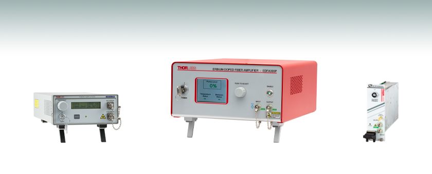
- Saturation Output Power of >20 dBm or >24.5 dBm
- Single Mode or Polarization-Maintaining Output
- Low-Noise, High-Gain Performance
- Turnkey Benchtop Systems or PXIe Plug-in Modules
EDFA300P
Polarization-Maintaining EDFA, >24.5 dBm Output Power
EDFA100S
Single Mode EDFA, >20 dBm Output Power
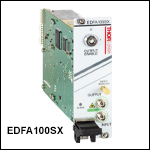
EDFA300SX
PXIe Plug-In Module,
>24.5 dBm Output Power

Please Wait
| Key System Specificationsa | |||||
|---|---|---|---|---|---|
| Item # | EDFA100S(X) | EDFA100P(X) | EDFA300S(X) | EDFA300P(X) | |
| Output Powerb (@ 3 dBm Input Power) |
>20 dBm | >24.5 dBm | |||
| Small Signal Gainb (@ -20 dBm Input Power) |
>30 dB | >28 dB | >40 dB | ||
| Noise Figureb (@ 3 dBm Input Power) |
<5 dB | <6 dB | |||
| Polarization Extinction Ratio | N/A | >25 dB | N/A | >25 dB | |
| Polarization-Dependent Gain | <0.5 dB | N/A | <0.5 dB | N/A | |
| Feature Comparison | |||||
|---|---|---|---|---|---|
| Item # | EDFA100S/ EDFA100P |
EDFA100SX/ EDFA100PX |
EDFA300S/ EDFA300P |
EDFA300SX/ EDFA300PX |
|
| Front Panel Interface |  |
- |  |
- | |
| Current Control Mode |  |
 a a |
 |
 a a |
|
| Power Control Mode | - |  a a |
 a a |
 a a |
|
| Gain Control Mode | - |  a a |
 a a |
 a a |
|
| Remote Control Interface | USB | PXIe | USB | PXIe | |
Features
- Operating Wavelength Range: 1530 - 1565 nm (C-Band)
- Available in Eight Models (See Table on the Right)
- Both Benchtop Systems and Plug-In Modules are Available
- Ideal for Use as a Preamplifier or Booster Amplifier in Data Communication Links
- Low Dispersion Design for Ultrafast Pulse Applications
- Front Panel Controls and Remote Control Over USB for Benchtop Systems
- Custom Dispersion-Compensating Patch Cables are Available Upon Request; Contact Tech Sales for Details
- Gain-Flattening Filters Available for the EDFA100 Series Amplifiers
Thorlabs' core-pumped erbium-doped fiber amplifiers (EDFAs) provide high small signal gains and output powers in a compact, turnkey benchtop package or a plug-in PXIe module with FC/APC (2.0 mm narrow key) input and output connectors. Our EDFAs are available in two output powers, >20 dBm or >24.5 dBm, which correspond to the EDFA100 and EDFA300 series amplifiers, respectively. With a <0.06 ps/nm dispersion that minimizes pulse broadening, the EDFA100 amplifiers are designed for femtosecond pulse amplification; see the fs Pulse Amplification tab for more information. The EDFA300 amplifiers, which provide higher output power and higher gain than the EDFA100 devices, are recommended for use as booster amplifiers. For detailed specifications and typical performance graphs, see the Specs and Graphs tabs, respectively.
For additional flexibility, the EDFAs are available in single mode (SM) and polarization-maintaining (PM) models. The EDFA100S(X) and EDFA300S(X) SM amplifiers are polarization-insensitive, and the input and output fibers to the amplifier are standard single-mode fiber (SMF-28-J9). The EDFA100P(X) and EDFA300P(X) PM amplifiers are polarization sensitive, only amplifying light that is linearly polarized along the slow axis. The input and output fibers of the PM amplifiers are polarization maintaining fiber (PM1550-XP) and the connector keys are aligned to the slow axis of the fibers.
Operation Modes
The gain and output power of EDFA100 series benchtop amplifiers is determined by the pump current, which can be varied through the instrument's front panel or remotely via USB 2.0 connector. The EDFA300 series benchtop amplifiers can operate in three modes, including current, power, or gain control modes. Current control is available via the instrument front panel or remotely via USB, while power and gain adjustment modes are only available through a command-line interface.
Each amplifier has a corresponding plug-in module that is designed to be operated in a PXIe chassis. These plug-in modules can operate in three modes, constant current, constant power, and constant gain. Controls for all three modes are accessible via a computer connection to the PXIe chassis.
For applications that require EDFAs with custom form factors, power consumption, or optical specifications, please contact Tech Sales. Thorlabs also offers Ytterbium-Doped Fiber Amplifiers (YDFAs) and a Praseodymium-Doped Fiber Amplifier (PDFA), which operate in the 1025 - 1075 nm and 1280 - 1330 nm (O-band) wavelength ranges, respectively.
Gain Flattening Filters
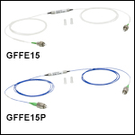
To flatten the gain spectrum of the EDFA100 series fiber amplifiers for applications that require equal gain across a wide spectral range, Thorlabs offers gain flattening filters (sold separately below). The filters are offered in SM (Item # GFFE15) and PM (Item # GFFE15P) models that are compatible with the EDFA100S(X) and EDFA100P(X) amplifiers, respectively.

Unless otherwise indicated, all specifications below are valid for CW inputs only.
| Item # | EDFA100S(X) | EDFA100P(X) |
|---|---|---|
| Amplifier Specifications (@ 1000 mA Pump Current) | ||
| Operating Wavelength Rangea | 1530 - 1565 nm | |
| Saturated Output Powerb,c (@ 3 dBm Input Power) |
>20 dBm | |
| Small Signal Gainb (@ -20 dBm Input Power) | >30 dB | >28 dB |
| Noise Figureb (@ 3 dBm Input Power) | <5 dB | |
| Output Power Stabilityd (Constant Current Modee @ 3 dBm Input Power) |
<±2% Over 24 Hours | |
| Output Power Stabilityd (Constant Power Mode @ 3 dBm Input Power) | <±0.5% Over 24 Hour (EDFA100 Series PXIe Modules Only)f |
|
| Total Dispersion Within Amplifierg | <0.06 ps/nm | |
| Laser Class | 3B | |
| Fiber Specifications | ||
| Output Polarization | Random | Linear, Aligned to Slow Axis |
| Polarization Extinction Ratio | N/A | >25 dB |
| Polarization-Dependent Gain | <0.5 dB | N/A |
| Return Loss at Input Port | >50 dB | |
| Input / Output Isolation | >30 dB | |
| Input / Output Fiber Type | SMF-28-J9 | PM1550-XP |
| Input / Output Fiber Connectors | FC/APC Compatible, 2.0 mm Narrow Key |
|
| Absolute Maximum Ratings | |
|---|---|
| Absolute Maximum Input Power | 10 dBm |
| Absolute Maximum Output Power | 23 dBm |
| Operating Temperature | 15 to 35 °C |
| Storage Temperature | 0 to 50 °C |
| General Specifications | ||
|---|---|---|
| Item | EDFA100 Series Benchtop Systems |
EDFA100 Series PXIe Modules |
| Input Voltage | 100 - 240 VAC, 50 - 60 Hz | - |
| Input Power | 20 VA (Max) | - |
| Fuse Rating | 500 mA | - |
| Fuse Type | IEC60127-2/III (250 VA, Slow Blow Type "T") | - |
| Electrical Power (From PXIe Chassis) |
- | 12 W (1 A @ 12 V)a |
| Dimensions (W x H x D) |
146.3 mm x 77.7 mm x 308.9 mm (5.76" x 3.06" x 12.16") |
40.3 mm x 128.7 mm x 207.2 mm (1.59" x 5.07" x 8.16") |
| Weight | 2.08 kg (4.58 lbs) | 0.45 kg (1 lb) |
Unless otherwise indicated, all specifications below are valid for CW inputs only.
| Item # | EDFA300S(X) | EDFA300P(X) |
|---|---|---|
| Amplifier Specifications (@ Max Pump Currenta) | ||
| Operating Wavelength Rangeb | 1530 - 1565 nm | |
| Saturated Output Powerc,d | >24.5 dBm | |
| Small Signal Gainc (@ -20 dBm Input Power) | >40 dB | |
| Noise Figurec (@ 3 dBm Input Power) | <6 dB | |
| Output Power Stabilitye (Constant Current Mode @ 3 dBm Input Power) | <±2% Over 24 Hours | |
| Output Power Stabilitye (Constant Power Mode @ 3 dBm Input Power) | <±0.5% Over 24 Hours | |
| Total Dispersion Within Amplifierf | <0.14 ps/nm | |
| Laser Class | 3B | |
| Fiber Specifications | ||
| Output Polarization | Random | Linear, Aligned to Slow Axis |
| Polarization Extinction Ratio | N/A | >25 dB |
| Polarization-Dependent Gain | <0.5 dB | N/A |
| Return Loss at Input Port | >50 dB | |
| Input / Output Isolation | >30 dB | |
| Input / Output Fiber Type | SMF-28-J9 | PM1550-XP |
| Input / Output Fiber Connectors | FC/APC Compatible, 2.0 mm Narrow Key |
|
| Absolute Maximum Ratings | |
|---|---|
| Absolute Maximum Input Power | 13 dBm |
| Absolute Maximum Output Power | 26 dBm |
| Operating Temperature | 15 to 30 °C |
| Storage Temperature | -10 to 40 °C |
| General Specifications | ||
|---|---|---|
| Item | EDFA300 Series Benchtop Systems |
EDFA300 Series PXIe Modules |
| Input Voltage | 100 - 240 VAC, 50 - 60 Hz | - |
| Input Power | 20 W (Max) | - |
| Fuse Rating | 2 A, 250 V | - |
| Fuse Type | Time-Lag (Slow-Blow) | - |
| Fuse Size | 5 mm x 20 mm | - |
| Electrical Power (From PXIe Chassis) |
- | 12 W (1 A @ 12 V)a |
| Dimensions (W x H x D) |
250.0 mm x 122.2 mm x 300.0 mm (9.84" x 4.81" x 11.81") |
40.3 mm x 128.7 mm x 207.2 mm (1.59" x 5.07" x 8.16") |
| Weight | 3.4 kg (7.5 lbs) | 0.45 kg (1 lb) |
Performance Graphs
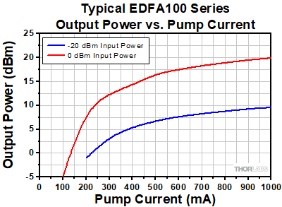
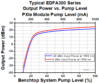
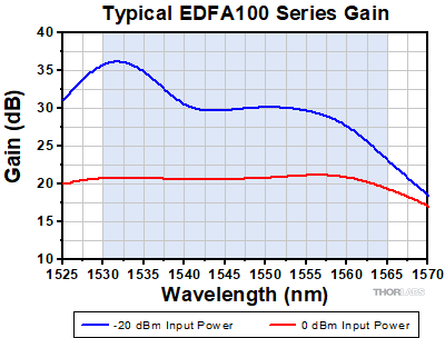
All EDFA100 Series performance graphs are representative of the EDFA100S(X) and EDFA100P(X) devices, and were obtained using a CW input, the maximum pump current of 1000 mA, and the factory pump temperature setting of 25 °C unless otherwise stated. EDFA300 Series performance graphs are taken with the maximum pump level and are representative of the EDFA300S(X) and EDFA300P(X) devices. Note that this data reflects the typical performance of our EDFAs, and is presented for reference only. The guaranteed specifications for all models are shown in the Specs tab.
Output Power Scaling
Click to Enlarge
Click for Raw Data
Typical EDFA100 Series Output Power at 1550 nm as a Function of
Pump Current
Click to Enlarge
Click for Raw Data
The typical EDFA300 series benchtop and EDFA300 series PXIe module output power at 1550 nm as a function of pump level. Please note that the pump current in the EDFA300 series PXIe modules is specified in mA as opposed to percentage. The maximum current in the EDFA300 series PXIe modules is 1000 mA, and all current values can be converted to percentage by normalizing the value to the 1000 mA maximum.
Gain
Click to Enlarge
Click for Raw Data
The typical EDFA100 Series gain as a function of the wavelength. The blue-shaded region denotes the specified operating wavelength range. For applications that require equal gain across a wide wavelength range, gain flattening filters for use with the EDFA100x are also available below.
Click to Enlarge
Click for Raw Data
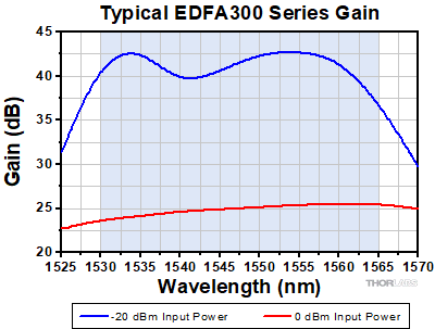
The typical EDFA300 Series gain as a function of the wavelength. The blue-shaded region denotes the specified operating wavelength range.
Noise Figure
Click to Enlarge
Click for Raw Data
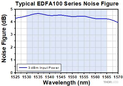
The typical EDFA100 Series noise figure as a function of the wavelength. The blue-shaded region denotes the specified operating wavelength range.
Click to Enlarge
Click for Raw Data
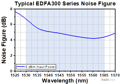
The typical EDFA300 Series noise figure as a function of the wavelength. The blue-shaded region denotes the specified operating wavelength range.
Femtosecond Pulse Amplification with the EDFA100x Amplifiers
Compared to booster optical amplifiers (BOAs) and semiconductor optical amplifiers (SOAs), erbium-doped fiber amplifiers (EDFAs) can amplify femtosecond pulses to significantly higher peak power levels. Details on the amplification mechanisms involved are provided in the Amplifier Comparison section at the bottom of this tab.
Below, we present measurements that show how the temporal profile of a 430 fs FWHM input pulse at 1550 nm is affected by propagation through the EDFA100P amplifier.
Experimental Setup
Femtosecond laser pulses centered at 1550 nm were emitted by an erbium fiber oscillator. The 3 dB spectral bandwidth of these pulses was measured to be 9 nm, corresponding to a transform-limited pulse width of 290 fs FWHM; the actual pulse width was measured by an intensity autocorrelator as 430 fs FWHM. The average output power of the fiber oscillator was 1.1 mW. Since the repetition rate of the fiber oscillator was 50 MHz, the measured pulse energy was 22 pJ.
These 430 fs FWHM, 22 pJ pulses were propagated into the EDFA100P amplifier. In some cases, the fiber oscillator was connected directly to the amplifier, while in others, the fiber oscillator was connected to the amplifier through an intermediary dispersion-compensating fiber patch cable. The total output power was varied by adjusting the EDFA100P pump current. We measured the temporal profile of the amplified output pulses as a function of the output power using an intensity autocorrelator.
Results
We characterized the amplified output pulses at three output pulse energies: 0.3 nJ, 0.6 nJ, and 1.1 nJ. The measurements were stopped at 1.1 nJ output pulse energy because nonlinearities appeared in the temporal profile. The data in each graph has been normalized to make the shapes of the autocorrelations easier to compare.
Click to Enlarge
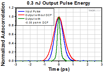
When the amplifier was set to 0.3 nJ output pulse energy, we observed minimal distortion to the temporal profile of the output pulse. The use of a dispersion-compensating fiber (DCF) compressed the output pulse to 150 fs.
| 0.3 nJ Test | Measured Pulse Width (FWHM) | Calculated Peak Power |
|---|---|---|
| Input Pulse | 430 fs | 45 W |
| Output Pulse (No DCF Precompensation) |
570 fs | 0.46 kW |
| Output Pulse (-0.05 ps/nm DCF Precompensation) |
150 fs | 1.76 kW |

Click to Enlarge
When the amplifier output pulse energy was doubled to 0.6 nJ, there was still minimal distortion to the non-precompensated output pulse. By applying precompensation, the output pulse was compressed to 88 fs, but pedestals associated with nonlinearities appeared on the sides. The peak output power in the precompensated case was 6 kW.
| 0.6 nJ Test | Measured Pulse Width (FWHM) |
Calculated Peak Power |
|---|---|---|
| Input Pulse | 430 fs | 45 W |
| Output Pulse (No DCF Precompensation) |
480 fs | 1.1 kW |
| Output Pulse (-0.05 ps/nm DCF Precompensation) |
88 fs | 6 kW |
Click to Enlarge
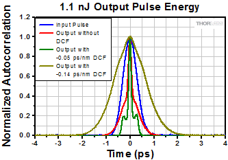
When the output pulse energy was doubled again to 1.1 nJ, significant distortions appeared in the non-precompensated pulse. Our previous -0.05 ps/nm DCF precompensation led to strong pedestals on the sides. A larger DCF precompensation of -0.14 ps/nm nearly removed the nonlinearities, but the output pulse broadened to 970 fs.
| 1.1 nJ Test | Measured Pulse Width (FWHM) | Calculated Peak Power |
|---|---|---|
| Input Pulse | 430 fs | 45 W |
| Output Pulse (No DCF Precompensation) |
140 fsa | - |
| Output Pulse (-0.05 ps/nm DCF Precompensation) |
80 fsa | - |
| Output Pulse (-0.14 ps/nm DCF Precompensation) |
970 fs | 1 kW |
Conclusion
When the peak power of the output pulse is ~1 kW or lower, nonlinearities in the temporal profile of the output pulse are minimal. (This peak power limit corresponds to a B integral between 1 and 2, below the limit at which nonlinear optical effects can become significant.) As the peak power increases beyond ~1 kW, spectral broadening due to self-phase modulation and other nonlinear optical effects compresses the pulse width and distorts the temporal profile. A careful balance between the initial chirp on the pulse, the amplifier dispersion, and the pulse energy can produce nonlinearly compressed pulses with low distortion.
An example of this is shown in the 0.6 nJ case above. When used with a femtosecond erbium oscillator and a precompensating fiber, the EDFA100P amplifier is capable of producing <100 fs pulses that have peak power of 6 kW. Without a precompensating fiber, the amplifier still provides high gain and minimal temporal distortion by keeping the peak power of the output pulse (and the B integral) below the threshold for nonlinearity.
Amplifier Comparison
Fiber amplifiers such as EDFAs and YDFAs are typically better suited than semiconductor optical amplifiers (e.g., BOAs and SOAs) for amplifying femtosecond laser pulses. These amplifier types differ in their saturation energies, their gain saturation dynamics, and their free carrier lifetimes. In semiconductor amplifiers, the saturation energies are relatively low, on the order of a few picojoules. This limits the amplified pulse energy that can be achieved by semiconductor amplifiers. By way of comparison, in fiber amplifiers, the saturation energies exceed microjoule levels. Additionally, the gain recovery times in semiconductor amplifiers are governed by the carrier lifetime, which is in the 10 ps to 100 ps timescale. The carrier lifetime of fiber amplifiers is typically in the 10 µs to 1 ms timescale.
Consider the case of a mode-locked femtosecond laser with a repetition rate on the order of 1 MHz. For pulse energies well below the saturation energy of the semiconductor amplifiers, the pulses will be amplified with minimal distortion. However, once the pulse energy exceeds the saturation energy, the amplification will saturate during the pulse, leading to a gain difference over the pulse's temporal profile and distorting the pulse shape. Since fiber amplifiers have higher saturation energies than semiconductor amplifiers, they are less prone to experience gain saturation by this mechanism.
Because the gain recovery time of a semiconductor amplifier (10 ps to 100 ps timescale) is shorter than the repetition period, the gain medium recovers before the next pulse in the pulse train arrives at the semiconductor amplifier. Therefore the same process is repeated for each pulse. In fiber amplifiers, the free carrier lifetime (10 µs to 1 ms timescale) is much longer than the repetition period. Consequently, fiber amplifiers can be thought of as responding to the pulse's average power, as opposed to its peak power.
An additional point that is especially relevant to femtosecond pulses is the role of nonlinear processes in the amplifier. While the nonlinear response of a fiber amplifier is almost instantaneous, the nonlinear response time of a semiconductor amplifier is in the 10 ps to 100 ps timescale, as it is related to its carrier lifetime. This ps timescale represents another source of pulse distortions when the pulse energy exceeds the saturation energy.
EDFA100 Series Benchtop System Front and Back Panels
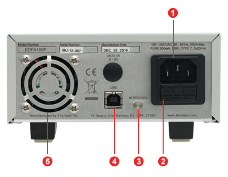
Click to Enlarge
Back Panel
Click to Enlarge
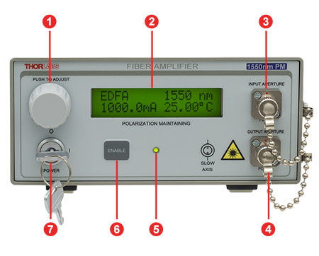
Front Panel
| Back Panel | |
|---|---|
| Callout | Description |
| 1 | AC Power Cord Connector |
| 2 | Fuse Tray |
| 3 | Remote Interlock |
| 4 | USB Port for Remote Interface |
| 5 | Cooling Fan (Do Not Block) |
| Front Panel | |
|---|---|
| Callout | Description |
| 1 | Control Knob to Adjust Pump Laser Current and Temperature |
| 2 | Display to Show Pump Laser Temperature and Drive Current |
| 3 | Optical Input for Single Mode FC/APC Fiber Connector |
| 4 | Optical Output for Single Mode FC/APC Fiber Connector |
| 5 | Amplifier Emission Indicator |
| 6 | Amplifier Enable Switch |
| 7 | Key Switch for Power |
EDFA300 Series Benchtop System Front and Back Panels
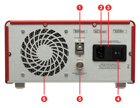
Click to Enlarge
Back Panel
Click to Enlarge
Front Panel
| Back Panel | |
|---|---|
| Callout | Description |
| 1 | USB Port for Diagnostics and Remote Interface |
| 2 | AC Power Cord Connector |
| 3 | Fuse Tray |
| 4 | AC Power Switch |
| 5 | Remote Interlock Input (BNC) |
| 6 | Cooling Fan (Do Not Block) |
| Front Panel | |
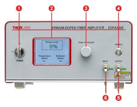
|---|---|
| Callout | Description |
| 1 | Key Switch for Power |
| 2 | Display to Show Pump Level, Temperature Status, and Emission Status |
| 3 | Control Knob to Adjust Pump Laser Current |
| 4 | Amplifier Enable Switch and Emission Indicator |
| 5 | Optical Output for Single Mode FC/APC Fiber Connector |
| 6 | Optical Input for Single Mode FC/APC Fiber Connector |
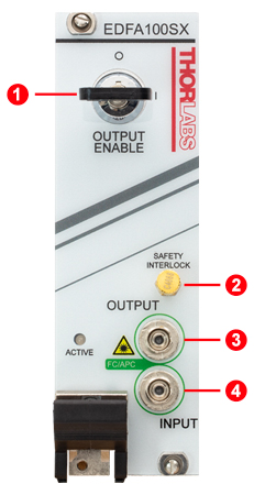
EDFA100 Series and EDFA300 Series PXIe Module Front Panel
| Callout | Description |
|---|---|
| 1 | Output Enable Key-Lock Switch |
| 2 | Remote Interlock Connector: SMB Female |
| 3 | Output: FC/APC |
| 4 | Input: FC/APC |
Shipping List
Included with Item #s EDFA100S and EDFA100P:
- Erbium-Doped Fiber Amplifier in Benchtop Package
- Amplifier Enable Key (Qty. 2)
- Interlock-Shorting Pin
- FBC250 Bulkhead and Connector Cleaner
- Region-Specific Power Cord
- Printed Manual
Included with Item #s EDFA300S and EDFA300P:
- Erbium-Doped Fiber Amplifier in Benchtop Package
- Interlock-Shorting BNC Connector
- Region-Specific Power Cord
- FBC250 Bulkhead and Connector Cleaner
- 1 m Patch Cable with FC/APC Connectors (for Connection to the Output Port)
- EDFA300S: SMF-28 Ultra SM Patch Cable (Item # P3-SMF28Y-FC-1 with Ø900 µm Jacket or P3-SMF28E-FC-1 with Ø3 mm Jacket)
- EDFA300P: PM1550-XP (PANDA) PM Patch Cable (Item # P3-1550PMY-1 with Ø900 µm Jacket or P3-1550PM-FC-1 with Ø3 mm Jacket)
- Sacrificial Fiber Interface (for Connection to the Output Port)*
*If the sacrifical interface becomes damaged, replacements are available by contacting Tech Sales.
Included with Item #s EDFA100SX, EDFA100PX, EDFA300SX, and EDFA300PX:
- Erbium-Doped Fiber Amplifier in PXIe-Compatible Module Package
- Amplified Enable Key (Qty. 2)
- FBC250 Bulkhead and Connector Cleaner
- Cap for FC/APC Connector (Qty. 2)
| Posted Comments: | |
user
(posted 2025-04-15 17:18:44.05) Hi, we have a EDFA100S and would like to know if its able to amplify low optical powers on the order of 1nW or -60dBm. Looking around the graphs only goes to -30dBm. jpoling
(posted 2025-04-22 12:58:02.0) Thank you for contacting Thorlabs. The input signal into the EDFA must be at least greater than the background noise that is characteristic of the EDFA in order for the amplified signal to be discernable. For this reason, we would not recommend amplifying signals smaller than -40 dBm. Yi-Ru CHEN
(posted 2024-07-17 10:03:11.713) Hello, do you provide the driver for Windows 11? jpolaris
(posted 2024-07-23 03:41:21.0) Thank you for contacting Thorlabs. We tested the current EDFA100P drivers with a Windows 11 machine and found them to be compatible. These drivers are downloadable from the following link. https://www.thorlabs.com/software_pages/ViewSoftwarePage.cfm?Code=LFL Vladimir Zenin
(posted 2024-07-02 12:37:17.57) Hi Thorlabs,
I am curious about using EDFA100P for amplification of fs laser pulses beyond 1 nJ. In the tab 'fs Pulse Amplification' you mention that the output beyond 1 nJ leads to distortions of the temporal profile of the pulse due to nonlinearities, even when using precompensation. However, what if I first broaden my fs pulse (for example, run it through a fiber), to reduce the peak power, then amplify it, and then compress it with dispersion compensating power?
Another question: you mention that you used 'erbium fiber oscillator' - which one was it?
Thank you in advance! cdolbashian
(posted 2024-07-19 03:35:18.0) Thank you for reaching out to us with this inquiry. It is certainly possible to achieve higher pulse energies given the correct pre-conditioning of your pulse. I have contacted you directly to discuss, theoretically, how you would achieve such performance. Srinivas Bala
(posted 2024-02-19 19:06:37.12) Hello,
We are looking for an EDFA to work with a Menlo Femto Second Optical Frequency Comb to amplify a narrow wavelength range between 1559nm to 1561 nm.
In our process we would filter the output from the Optical Frequency Comb which is +20 dBm @1555-15765nm. After filtering the 10nm band we will have a narrow wavelength between 1559.5nm to 1560.5nm and this would result in low power in the order of -50dbm. Do you have a preamplifier that can handle such a low input? The pulse width will be around 300 fs. Menlo informed us that they buy these EDFA's from you and told us to contact you. We need this Pre Amplifer to have a gain of around 25-30dbm or better and should be powered by 12V DC.
We are not sure if we need a DCF. Please advise.
Thanks
Srinivas ksosnowski
(posted 2024-02-26 01:22:49.0) Hello Srinivas, thanks for reaching out to Thorlabs. Our EDFA's do have small signal gain in the neighborhood of 30dB or better (28dB on the PM version). -50dBm input is well within the -20dBm small signal gain spec. Femtosecond Pulse Amplification is a common application of these fiber amplifiers. We designed the EDFA100 series with <0.06 ps/nm internal dispersion to help minimize pulse broadening. However we do also offer Dispersion Compensating Fiber patch cables if additional compensation is required. While our benchtop units require mains voltage (100 - 240 VAC) to operate, we do offer some PXIe card format options like EDFA100SX which operate on 12V. I have reached out directly to discuss this application in further detail. Yixiu Shen
(posted 2023-12-14 15:31:31.247) I am using the EDFA 100P's with an input power of 3mW, why is the output power not up to the expected amplification or I only have a very small output, I am also experiencing this problem after purchasing a new EDFA of the same type. (I am sure that the wavelength and the fibre used are up to standard) Yazan Lampert
(posted 2023-10-02 22:02:26.0) Dear all,
we would like to know if the polarization dependent gain is caused by the isolator inside the EDFA or if it's caused by the doped fiber its self.
Best,
Yazan cdolbashian
(posted 2023-10-18 04:46:19.0) Thank you for reaching out to us with this inquiry. The polarization dependent gain can be attributed to the pair of isolators with the assembly. I have contacted you directly to discuss this further. Zhenghao Liu
(posted 2023-03-09 12:54:39.86) Hi,
Would you please specify - what is the length of the fiber inside your EDFA100P model?
Many thanks,
Zhenghao jdelia
(posted 2023-03-09 01:58:19.0) Thank you for contacting Thorlabs. The length of fiber inside the EDFA100P is ~ 3.3 m +/- 0.5 m. Rudianto Silitonga
(posted 2022-09-24 16:08:30.167) How do I get your product? jdelia
(posted 2022-09-26 03:16:34.0) Thank you for contacting Thorlabs. You can order our products by adding them to your shopping cart directly on the website or by requesting a quote from our sales team, who you can reach at sales@thorlabs.com or 1-973-300-3000. Nicolas Forget
(posted 2019-10-28 17:09:49.317) Hi, I would like to know whether the EDFA100P can be used both ways, ie with light coming in from both the input and output ports.
Best regards, Nicolas YLohia
(posted 2019-10-29 11:10:36.0) Hello Nicolas, the EDFA is not bidirectional -- the input must be supplied via the "Input Port". If you require a bidirectional operation, then our semiconductor optical amplifiers such as the SOA1117P would be a better fit. The SOA is built with a symmetric structure, so when operating in the reverse direction, the gain will stay the same but saturation power and noise figure may be different. Tiong Leh (Johnny) Yap
(posted 2019-10-16 18:17:04.947) Hi,
I would like to ask for quotation for EDFA100S.
Thank you.
Regards,
Johnny YLohia
(posted 2019-10-16 10:51:11.0) Hello Johnny, thank you for contacting Thorlabs. Quotes can be requested by emailing our Sales Team at sales@thorlabs.com or selecting "Request Quote" from your cart. Yohan Barbarin
(posted 2019-10-08 03:07:20.72) Dear,
We have an issue with the interlock. It looks like it is only mecanical and not electronical.
Could you please give us more information about the electrical specs of the interlock input.
Best regards,
Yohan YLohia
(posted 2019-10-08 02:33:52.0) Hello Yohan, thank you for contacting Thorlabs. The electrical specs for the interlock can be found on Page 10 of the manual: https://www.thorlabs.com/_sd.cfm?fileName=TTN118382-D02.pdf&partNumber=EDFA100S user
(posted 2019-09-04 08:30:52.267) Please can you provide advice on the lowest input power to use with the EDFA100S ?
For example, do you have a graph to show how the SNR in the output varies as a function of the input power ?
The wavelength I want to use is 1550 nm.
I would like to consider input powers down to - 40 dBm, maybe even lower. I notice your graph stops at minus 30 dBm.
Thank you asundararaj
(posted 2019-09-12 01:39:32.0) Thank you for your feedback. The EDFA100S can be seeded with -40 dBm input power. However, the SNR of the output will be reduced as input power is increased. I have contacted you directly to discuss this further. cees de Kok
(posted 2019-03-13 03:54:32.757) We are considering the purchase of the EDFA100P.
We are also working at wavelength on or a little bit below 1520 nm. The gain curve in the documentation which goes as low as 1525 nm seems to still not go down very steeply below 1525...
So my question is: do you have gain-data for 1520 nm or even lower? llamb
(posted 2019-03-15 08:29:36.0) Hello, thank you for your feedback. I have emailed you directly with additional data. k.l.perrier
(posted 2019-03-06 11:08:13.807) We are interested in the Gain and Noise spectrum below 1525nm. Is it possible to provide us the graphs from 1490nm-1570nm or similar range?
Thank you llamb
(posted 2019-03-15 08:23:53.0) Thank you for contacting Thorlabs. I have reached out to you directly with further data. |

Click to Enlarge
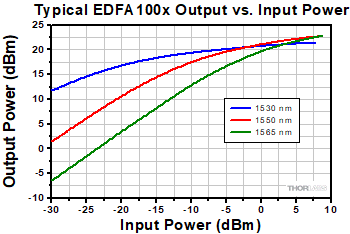
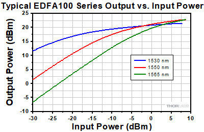
This plot gives the wavelength-dependent output power as a function of input power for our EDFA100x units. Data was taken using a CW input, the maximum pump current of 1000 mA, and the factory pump temperature setting of 25 °C. A complete set of performance graphs is available on the Graphs tab.
- Ideal for Use as a Preamplifier for Input Signal Powers ≥ -30 dBm
- <0.06 ps/nm Dispersion Within Amplifier to Minimize Pulse Broadening
- Provides Minimal Nonlinearity for Ultrafast Applications
- Constant Current Mode Operation
- Suitable for CW and Pulsed Signals
Thorlabs' EDFA100x core-pumped erbium-doped fiber amplifiers (EDFAs) offer >20 dBm output power with a low noise figure of <5 dB. The EDFA100S is a single mode EDFA with minimal sensitivity to the input light polarization, while the EFDA100P is a polarization-maintaining EDFA that only amplifies light polarized along the slow axis of the fiber. Each EDFA100x includes built-in input and output isolators. In order to support applications involving femtosecond pulses, they are engineered to impart minimal dispersion. The fs Pulse Amplification tab contains more details on femtosecond operation. If additional dispersion compensation is needed at the input or output, dispersion-compensating patch cables are available from stock or patch cables with custom dispersion compensation are available from Tech Sales.
The pump current of the EDFA100x amplifier is adjustable through the instrument's front panel, allowing the user to vary the gain and output power of the amplifier (see the Front & Back Panels tab). In addition, remote control of the pump current is supported by sending serial commands via a USB 2.0 connector; drivers are available on the Software tab. For added safety, the user may connect an interlock circuit to the 2.5 mm mono jack on the rear panel.
Each EDFA100x uses a universal power supply allowing operation over 100 - 240 VAC, 50 - 60 Hz without the need to select the line voltage. A region-specific power cord is included. For a full list of items shipped with each EDFA100x, please see the Shipping List tab.

Click to Enlarge
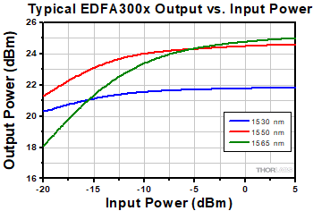
This plot gives the wavelength-dependent output power as a function of input power for our EDFA300x units. Data was taken with the pump level set to 100%. A complete set of performance graphs is available on the Graphs tab.
- Ideal Uses:
- Preamplifier for Signal Powers ≥ -20 dBm
- Booster Between a Preamplifier and a Power-Amplifier Stage
- Constant Current, Power, and Gain Operation Modes
- Suitable for CW and Pulsed Signals
Thorlabs' EDFA300x core-pumped erbium-doped fiber amplifiers (EDFAs) offer >24.5 dBm output power with a low noise figure of <6 dB. The EDFA300S is a single mode EDFA with minimal sensitivity to the input light polarization, while the EFDA300P is a polarization-maintaining EDFA that only amplifies input light polarized along the slow axis of the fiber. Each EDFA300x instrument includes built-in input and output isolators to protect the input laser source from any amplified spontaneous emission or back reflections, as well as to prevent the pump light from exiting the amplifier. If additional dispersion compensation is needed at the input or output, dispersion-compensating patch cables are available from stock or patch cables with custom dispersion compensation are available from Tech Sales.
Each unit includes a 1 m FC/APC patch cable, and this cable should be connected to the output at all times to protect the output receptacle from the optical damage caused by repeated connections. A sacrificial optical interface compatible with FC/APC connectors is also supplied with each unit, which can be plugged into the output port of the amplifier, and all fiber cable connections can be made to this interface. Note that this option will introduce approximately 0.7 dB of extra insertion loss, but it offers the advantage of preventing direct contact between a fiber cable and the internal connector surface. For a full list of items shipped with each EDFA300x, please see the Shipping List tab.
Operation Modes
The EDFA300x devices can be operated in three modes, including automatic current control (ACC), automatic power control (APC), and automatic gain control (AGC). ACC mode drives the pump current in the EDFA at a fixed level and is accessible through the instrument’s front panel. The user can vary the gain and output power level of the instrument by adjusting the pump current level. These fiber amplifiers can also be operated in APC or AGC mode, which maintain fixed output power or fixed gain, respectively. Note that these two operation modes are only accessible through a command-line interface; the EDFA300x device can be connected to a PC via the USB port on the back panel of the instrument; see the Front & Back Panels tab for details.
The command line interface can also be used to enable or disable the amplifier, set the current level in the ACC mode, or read status indicators. The indicators available through the USB interface include temperature error, interlock status, and emission status. For more details on these features, please refer to the instrument manual.
Each EDFA uses a universal power supply allowing operation over 100 - 240 VAC, 50 - 60 Hz without the need to select the line voltage. A region-specific power cord is included.

Click to Enlarge
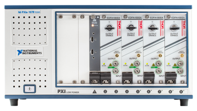
Four EDFA100SX Modules in a PXI-Compatible Chassis (Not Included)
- Compact PXIe Packaging
- Identical Optical Performance to the EDFA100x or EDFA300x Benchtop Amplifiers
- Customizable Front and Back Panel (Contact Us for Details)
The EDFA100 series and EDFA300 series PXI Express (PXIe) Plug-In Modules provide identical optical performance to their respective EDFA100x and EDFA300x benchtop amplifiers. The EDFA100SX and EDFA100PX modules have the added functionality of operating in constant power or constant gain mode, in addition to the constant current operation of the EDFA100x benchtop amplifiers. The EDFA300 series PXIe modules operate over the same three modes as the EDFA300x benchtop amplifiers, constant current, constant power, and constant gain. These PXIe modules offer seamless integration into new or existing PXI test and measurement setups and are compatible with a broad range of existing electrical and optical plug-in modules. Additionally, the small form-factor of these module's 2-slot PXI card saves space, power consumption, and cost especially when multiple EDFA modules are required to operate in parallel. The module is ready to use when plugged into any PXIe-compatible chassis (not sold by Thorlabs). The image to the right shows an example where four EDFA100SX amplifiers are plugged into a 9-slot chassis.
The EDFA100 series and EDFA300 series plug-in modules are fully controlled through the PXI chassis using a PXI controller module and can be recognized as a serial port on a computer allowing serial communications with the device. A list of control commands for these modules is available through the manual. Additionally, a LabVIEW interface, which can operate multiple EDFA cards plugged into one PXIe chassis, can be provided upon request. Please contact Tech Sales with any inquiries.

Click to Enlarge
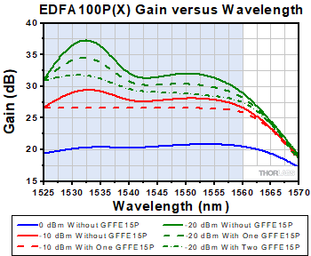
The typical gain of the EDFA100P(X) amplifier without and with the GFFE15P gain flattening filter with different input powers. The blue-shaded region indicates the gain-flattening wavelength range. The filter is optimal for a -10 dBm input power; the gain flatness improves from ~3 dBm (solid red line) to <0.5 dB with the filter (dashed red line). The gain flatness at -20 dBm input power has more variation without the filter (solid green line). While gain flatness can be improved with one filter (dashed green line), cascading two filters further flattens the signal (dashed-dotted green line). The gain spectrum with 0 dBm input power (solid blue line) cannot be further improved with the filter.
- Flatten Gain Spectrum of EDFA100 Series Erbium-Doped Fiber Amplifiers
- 1525 - 1570 nm Operating Wavelength Range
- Optimized for a -10 dBm Input Power
- Available in SM and PM Versions
Thorlabs' Gain Flattening Filters are designed for use with the EDFA100 series erbium-doped fiber amplifiers (EDFAs). The filters are offered in SM (Item # GFFE15) and PM (Item # GFFE15P) models that are compatible with the EDFA100S(X) and EDFA100P(X) amplifiers, respectively. These filters are intended to be connected to the output port of the EDFA and are designed to flatten the gain spectrum of the fiber amplifiers for applications that require equal gain across a wide spectral range. The gain spectrum of the EDFAs depends on the input power level with the gain variations increasing over the operating wavelength range as the input power is decreased. The design transmission curve of the filter, given below, flattens the gain of the EDFA100 series at -10 dBm input power.
One of the key specifications for the gain flattening filter is the peak-to-peak error function, which is defined as the difference between the measured transmission curve (in dB) and the design transmission curve (in dB). Each filter will have a transmission profile that deviates from the design curve to some level, and the error function captures this variation over the wavelength range. The peak-to-peak error function is a single valued specification defined as the difference between the maximum error function and the minimum error function. That value in dB is given in the specs table below.
The plot to the right shows the typical EDFA100P(X) amplifier gain versus wavelength for three different input power levels (0 dBm, -10 dBm, and -20 dBm). The filters are designed to provide optimal gain flatness at a -10 dBm input power level, as seen in the gain plot to the right. The gain flatness at -10 dBm input power over the 1525 - 1560 nm wavelength range is improved from ~3 dB without the filter to <0.5 dB after placing the GFFE15P filter. Similarly, the gain flatness at -20 dBm input power can be improved from ~8.5 dB to <6 dB over the same wavelength range by adding the filter. Since the gain at -20 dBm shows a larger variation versus wavelength compared to the -10 dBm case, cascading two filters can further improve the flatness to <4 dB as shown in the plot. When connecting two filters together, we recommend using either a ADAFC3 or ADAFCPM2 narrow key FC/APC fiber optic mating sleeve, which are suitable for SM and PM fibers, respectively. The gain spectrum of the EDFA100P(X) amplifier for 0 dBm input power level exhibits good flatness and cannot be further improved using these filters.
| Item # | GFFE15 | GFFE15P |
|---|---|---|
| Wavelength Rangea (Click for Design Profile) |
1525 nm - 1570 nm | |
| Insertion Lossb | <0.8 dB | |
| Peak-to-Peak Error Function | <0.5 dB | |
| Polarization-Dependent Loss | <0.1 dB | - |
| Extinction Ratio | - | 20 dB |
| Return Loss | >50 dB | |
| Connector Type | FC/APC | |
| Fiber Type |
SMF-28 In White Ø900 μm Tubing | PM1550-XP In Blue Ø900 μm Tubing |
| Compatible Amplifier | EDFA100S(X) | EDFA100P(X) |
 Products Home



 Zoom
Zoom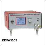
 Erbium-Doped Fiber Amplifiers (EDFA)