 Products Home / Lasers / Coherent Sources / Laser Diodes by Package & Type / Single-Frequency, Ultra-Low-Noise Laser, Extended Butterfly Package
Single-Frequency, Ultra-Low-Noise Laser, Extended Butterfly Package
- C-Band, Single-Frequency Laser Source
- 100 Hz Typical, 250 Hz Max Linewidth with 70 dB Typical SMSR
- Typical Relative Intensity Noise (RIN) of -165 dBc/Hz
- Integrated TEC Elements and Thermistors
- PM Fiber Pigtailed with FC/APC Connector
US Patents: 10193306, 10483718,
10476233, and 10454248
ULN15PC
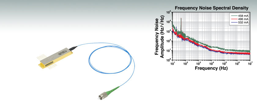
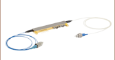
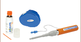
Ultra-Low-Noise Laser, Current Tuning, Extended Butterfly Package, PM Fiber
Frequency noise of an ultra-low-noise laser at various currents within a region of single mode operation. The peak in noise at 43 Hz is due to HVAC systems present in the testing facility. The data is typical, and performance will vary among individual lasers.


Please Wait
| Webpage Features | |
|---|---|
| Clicking this icon opens a window that contains specifications and mechanical drawings. | |
 |
Clicking this icon allows you to download our standard support documentation. |
|
Choose Item |
Clicking the words "Choose Item" opens a drop-down list containing all of the in-stock lasers around the desired center wavelength. The red icon next to the serial number then allows you to download L-I and spectral measurements for that serial-numbered device. |
Features
- 1550 nm Typical Center Wavelength
- Less than -165 dBc/Hz Relative Intensity Noise (RIN)
- 14-Pin Hermetically Sealed Extended Butterfly Package
- Two Integrated Thermoelectric Coolers (TEC) and Thermistors
- PM Fiber Pigtail with 2.0 mm Narrow Key FC/APC Connector
- Compatible with LM14TS Laser Mount
- Requires Low-Noise Current Source
Thorlabs' Ultra-Low-Noise (ULN) Hybrid Lasers provide signals with relative intensity noise below -165 dBc/Hz and typical (Lorentzian) linewidths of 100 Hz. The single mode output can reach optical powers of 140 mW with a side mode suppression ratio (SMSR) of 70 dB. These specifications are achieved through a patented design consisting of a single angled facet (SAF) gain chip coupled to a fiber Bragg grating (FBG) enclosed in a hermetically sealed case.1 Two integrated thermoelectric coolers (TECs) and thermistor pairs act in a closed loop to control the temperature of the gain chip and FBG independently. In addition, each laser features an auxiliary thermistor that monitors the case temperature and a built-in monitor photodiode.
The lasing spectrum of these sources changes between single longitudinal mode and multimode depending on the drive current. As the system experiences effects of hysteresis, the width of these ranges will also change depending on whether the drive current is being increased or decreased. Each laser's center wavelength is tested and reported on a serialized data sheet; this wavelength may be anywhere in the ITU C band (1530 - 1565 nm), but most of the devices below will operate at or near 1550 nm. Users should reference the laser's individual data sheet to see where these regions exist for their device. This is discussed further in the Operation tab above.
Specifications for each item can be found in the tables below and by clicking on the blue icons (![]() ). These specifications are typical values and the performance will vary from device to device. Each ultra-low-noise laser diode is serialized and shipped with individual test data. Customers can click "Choose Item" below to view a variety of available center wavelengths. The reported specifications are achievable by using a low-noise current supply. Customers that require a specific wavelength may contact Tech Support to place a special order.
). These specifications are typical values and the performance will vary from device to device. Each ultra-low-noise laser diode is serialized and shipped with individual test data. Customers can click "Choose Item" below to view a variety of available center wavelengths. The reported specifications are achievable by using a low-noise current supply. Customers that require a specific wavelength may contact Tech Support to place a special order.
The chosen current supply (Thorlabs does not currently offer one in its portfolio with sufficiently low noise for these lasers) should be given time to stabilize before the output of the laser is measured. In addition, an optical isolator should be placed at the output of the laser. We recommend the IOT-G-1550A dual-stage isolator, which can achieve a peak isolation of 55 dB; alternatively, two fiber-coupled isolators can be used in-line to achieve a similar isolation.
Thorlabs also offers a turnkey ULN laser system, which integrates the ULN15PC laser with a low-noise driver and temperature stabilization inside of a benchtop housing. Factory-set for single-frequency operation, this laser system has a preset drive current and FBG temperature.
Current-Tuning vs Temperature-Tuning Configurations
Our ultra-low-noise lasers are available in either a current- or temperature-tuning configuration. The current-tuning configuration is designed to maximize the range of drive currents where the laser operates in a single mode. The temperature-tuning configuration allows for independent adjustment of the FBG temperature without impacting the width of the mode-hop-free range. Users requiring the maximum possible mode-hop-free tuning and/or current range should select the current-tuning configuration, while users wishing to thermally tune the output wavelength without impacting the output power should select the temperature-tuning configuration. See the subgroups below for more information on the differences between these configurations. For more information on how these devices operate, see the Operation tab above.
Mounting and Care
Each laser is housed in an extended 14-pin butterfly-style package. This extended package is not compatible with standard 14-pin laser diode mounts but is compatible with the LM14TS Active Butterfly Mount. If not using Thorlabs' mount, the diode must be affixed to a purpose-built heat sink. The laser's case has four mounting slots for use with 2-56 (M2) screws. Note that the ultra-low-noise hybrid lasers are extremely sensitive to both seismic and acoustic vibrations, so a mounting fixture that dampens vibration is suggested. Thorlabs offers packs of fifty 2-56 screws (Item # SH2S019) as well as a 2-56 tap (Item # TAP256) to aid in installation. Mounting torque should not exceed 0.14 N•m (20 oz-in); this can be applied and checked using a torque driver.
We recommend cleaning the fiber connector before each use in case any dust or other contaminants have been deposited on the surface. The laser intensity at the center of the fiber tip can be very high and may burn the tip of the fiber if contaminants are present. While the connector is cleaned and capped before shipping, we cannot guarantee that it will remain free of contamination after it is removed from the package. We also recommend that the laser is turned off when connecting or disconnecting the device from other fibers.
1. Morton P, Morton M. "High-Power, Ultra-Low Noise Hybrid Lasers for Microwave Photonics and Optical Sensing." Journal of Lightwave Technology. 2018 November 1; 36: 5048-5057.
Single Longitudinal Mode Operation
Thorlabs' ULN hybrid lasers exhibit fluctuations between single and multimode operation. These regions of stable output change based on a number of factors.1 Here, we will describe how the drive current changes the single mode operating regions. Note: the following data is typical; users should reference the laser's serialized data sheet to see the drive currents that provide stable single mode operation for their particular device.
Longitudinal Mode Transitions
The fluctuations between single mode and multimode operation are due, in part, to the supported lasing modes within the cavity created between the high-reflectance back facet of the gain chip and fiber Bragg grating. The graph below shows the single mode powers for a representative ULN15PT temperature-tuning laser. Drive currents between the single mode ranges will result in multimode outputs. For that reason, the resulting powers were removed from the graph. As an example, when driven at approximately 220 mA, this unit will generate multimode output, while a 300 mA drive current will produce a single mode output. Current-tuning configurations of these lasers are designed to minimize these multimode regions.
Click to Enlarge
Click for Data
Each single mode region is shown; multimode regions have been removed.
Hysteresis
The single mode regions of the ULN hybrid lasers are not a static width; they change depending on whether the current is increased or decreased after single mode operation is reached. The graph below is of a representative ULN15PC current-tuning laser's power output when increasing and decreasing the current. Consider the laser's performance when driven with currents between 700 and 725 mA. If the current is increased from 700 mA, the output will not become single mode until a current of approximately 715 mA (red curves on the graph below); however, after entering this region of single mode operation, the drive current can be lowered to almost 700 mA with the laser cavity maintaining single mode operation (blue curves). When driving a ULN hybrid laser, it is important to keep in mind the direction of the current change to maintain stable operation.
 Click to Enlarge
Click for Data
The range of currents which produce single mode outputs is wider for decreasing currents compared to increasing currents.
Longitudinal Mode Shifts with TFBG
The grating period of the ULN laser's internal FBG changes based on its temperature. When using a temperature-tuning ULN laser, independently setting this temperature helps define the cavity's supported lasing modes and tune to a desired output wavelength. However, because the FBG temperature influences the supported lasing modes, the single mode regions shift. The graph below shows how the single mode operating regions change when adjusting the TFBG in a typical ULN15PT temperature-tuning laser. For a large enough temperature change, the laser will eventually move from single mode to multimode operation. If the laser is driven at a current at the edge of a region of single mode operation, this change can occur over just a few degrees Celsius. For this reason, we recommend monitoring the laser's output with an optical spectrum analyzer while temperature tuning to ensure that the output remains single mode.
 Click to Enlarge
Click for Data
Single mode regions will shift as TFBG changes, which may cause the laser to fall out of single mode operation at a fixed drive current.
Wavelength Shift
In addition affecting the laser's modes, changes in drive current will also shift the output wavelength. A representative graph of a ULN15PC laser's wavelength can be seen below. Each group of colored points indicates a mode-hop-free, single mode operating region. The same wavelength/current dependence can be seen in our temperature-tuning models; however these models are designed to provide wavelength tuning at a constant power by changing the fiber Bragg grating temperature. Note: the stepping structure of the center wavelengths is due to the resolution of the optical spectrum analyzer used to take the measurement; the change in wavelength is smooth across each region of single mode operation.
 Click to Enlarge
Click for Data
Within single mode operating regions, the center wavelength will shift with current. Each trendline indicates a region of single mode performance. The stepping structure of the measured data is due to the resolution of the optical spectrum analyzer used to take the measurement; the change in wavelength is smooth when in single mode operation.
1. Morton P, Morton M. "High-Power, Ultra-Low Noise Hybrid Lasers for Microwave Photonics and Optical Sensing." Journal of Lightwave Technology. 2018 November 1; 36: 5048-5057.
Extended Butterfly Package Pin Diagram
| Pin Identification | |||
|---|---|---|---|
| Pin | Assignment | Pin | Assignment |
| 1 | FBG TEC - | 8 | Photodiode Anode |
| 2 | FBG TEC + | 9 | Laser Diode Anode |
| 3 | Case Thermistor | 10 | Laser Diode Cathode |
| 4 | Case Thermistor | 11 | Chip Thermistor |
| 5 | Photodiode Cathode | 12 | Chip Thermistor |
| 6 | Chip TEC - | 13 | FBG Thermistor |
| 7 | Chip TEC + | 14 | FBG Thermistor |
ECL, DFB, VHG-Stabilized, DBR, and Hybrid Single-Frequency Lasers
Click to Enlarge
Figure 1: ECL Lasers have a Grating Outside of the Gain Chip
A wide variety of applications require tunable single-frequency operation of a laser system. In the world of diode lasers, there are currently four main configurations to obtain a single-frequency output: external cavity laser (ECL), distributed feedback (DFB), volume holographic grating (VHG), and distributed Bragg reflector (DBR). All four are capable of single-frequency output through the utilization of grating feedback. In addition, an ECL can be combined with a fiber Bragg grating (FBG) to create a hybrid design. However, each type of laser uses a different grating feedback configuration, which influences performance characteristics such as output power, tuning range, and side mode suppression ratio (SMSR). We discuss below some of the main differences between single-frequency diode lasers.
External Cavity Laser
The External Cavity Laser (ECL) is a versatile configuration that is compatible with most standard free space diode lasers. This means that the ECL can be used at a variety of wavelengths, dependent upon the internal laser diode gain element. A lens collimates the output of the diode, which is then incident upon a grating (see Figure 1). The grating provides optical feedback and is used to select the stabilized output wavelength. With proper optical design, the external cavity allows only a single longitudinal mode to lase, providing single-frequency laser output with high side mode suppression ratio (SMSR > 45 dB).
One of the main advantages of the ECL is that the relatively long cavity provides extremely narrow linewidths (<1 MHz). Additionally, since it can incorporate a variety of laser diodes, it remains one of the few configurations that can provide narrow linewidth emission at blue or red wavelengths. The ECL can have a large tuning range (>100 nm) but is often prone to mode hops, which are very dependent on the ECL's mechanical design as well as the quality of the antireflection (AR) coating on the laser diode.
Click to Enlarge
Figure 2: DFB Lasers Have a Bragg Reflector Along the Length of the Active Gain Medium
Distributed Feedback Laser
The Distributed Feedback (DFB) Laser (available in NIR and MIR) incorporates the grating within the laser diode structure itself (see Figure 2). This corrugated periodic structure coupled closely to the active region acts as a Bragg reflector, selecting a single longitudinal mode as the lasing mode. If the active region has enough gain at frequencies near the Bragg frequency, an end reflector is unnecessary, relying instead upon the Bragg reflector for all optical feedback and mode selection. Due to this “built-in” selection, a DFB can achieve single-frequency operation over broad temperature and current ranges. To aid in mode selection and improve manufacturing yield, DFB lasers often utilize a phase shift section within the diode structure as well.
The lasing wavelength for a DFB is approximately equal to the Bragg wavelength:

where λ is the wavelength, neff is the effective refractive index, and Λ is the grating period. By changing the effective index, the lasing wavelength can be tuned. This is accomplished through temperature and current tuning of the DFB.
The DFB has a relatively narrow tuning range: about 2 nm at 850 nm, about 4 nm at 1550 nm, or at least 1 cm-1 in the mid-IR (4.00 - 11.00 µm). However, over this tuning range, the DFB can achieve single-frequency operation, which means that this is a continuous tuning range without mode hops. Because of this feature, DFBs have become a popular and majority choice for real-world applications such as telecom and sensors. Since the cavity length of a DFB is rather short, the linewidths are typically in the 1 MHz to 10 MHz range. Additionally, the close coupling between the grating structure and the active region results in lower maximum output power compared to ECL and DBR lasers.
Click to Enlarge
Figure 3: VHG Lasers have a Volume Holographic Grating Outside of the Active Gain Medium
Volume-Holographic-Grating-Stabilized Laser
A Volume-Holographic-Grating-(VHG)-Stabilized Laser also uses a Bragg reflector, but in this case a transmission grating is placed in front of the laser diode output (see Figure 3). Since the grating is not part of the laser diode structure, it can be thermally decoupled from the laser diode, improving the wavelength stability of the device. The grating typically consists of a piece of photorefractive material (typically glass) which has a periodic variation in the index of refraction. Only the wavelength of light that satisfies the Bragg condition for the grating is reflected back into the laser cavity, which results in a laser with extremely wavelength-stable emission. A VHG-Stabilized laser can produce output with a similar linewidth to a DFB laser at higher powers that is wavelength-locked over a wide range of currents and temperatures.
Click to Enlarge
Figure 4: DBR Lasers have a Bragg Reflector Outside of the Active Gain Medium
Distributed Bragg Reflector Laser
Similar to DFBs, Distributed Bragg Reflector (DBR) Lasers incorporate an internal grating structure. However, whereas DFB lasers incorporate the grating structure continuously along the active region (gain region), DBR lasers place the grating structure(s) outside this region (see Figure 4). In general a DBR can incorporate various regions not typically found in a DFB that yield greater control and tuning range. For instance, a multiple-electrode DBR laser can include a phase-controlled region that allows the user to independently tune the phase apart from the grating period and laser diode current. When utilized together, the DBR can provide single-frequency operation over a broad tuning range. For example, high end sample-grating DBR lasers can have a tuning range as large as 30 - 40 nm. Unlike the DFB, the output is not mode hop free; hence, careful control of all inputs and temperature must be maintained.
In contrast to the complicated control structure for the multiple-electrode DBR, a simplified version of the DBR is engineered with just one electrode. This single-electrode DBR eliminates the complications of grating and phase control at the cost of tuning range. For this architecture type, the tuning range is similar to a DFB laser but will mode hop as a function of the applied current and temperature. Despite the disadvantage of mode hops, the single-electrode DBR does provide some advantages over its DFB cousin, namely higher output power because the grating is not continuous along the length of the device. Both DBR and DFB lasers have similar laser linewidths. Currently, Thorlabs offers only single-electrode DBR lasers.
Ultra-Low-Noise Hybrid Laser
Thorlabs Ultra-Low-Noise (ULN) Hybrid Lasers each consist of a single angled facet (SAF) gain chip coupled to an exceptionally long fiber Bragg grating (FBG). They are designed to create a laser cavity, similar to an ECL, through the length of fiber. This cavity provides the ULN hybrid laser with a very narrow line width on the order of 100 Hz and low relative intensity noise of -165 dBc/Hz (typical). The FBG reflects a portion of the light emitted from the gain medium while remaining thermally isolated from it. The grating period can be changed by introducing thermal stress to the fiber, allowing users to temperature tune the laser output while being able to independently stabilize the gain medium's temperature. Because the laser's configuration provides excellent low-noise performance, it is likely the laser will not be the limiting factor at low-noise levels. It is critical to monitor the laser's environment to limit external noise contributions like acoustic and seismic vibrations, as well as driving the laser with a low-noise current source.
Click to Enlarge
Figure 5: Thorlabs Hybrid Lasers have a Fiber Bragg Grating Coupled to the Active Gain Medium
Conclusion
ECL, DFB, VHG, DBR, and hybrid laser diodes provide single-frequency operation over their designed tuning range. The ECL can be designed for a larger selection of wavelengths than either the DFB or DBR. While prone to mode hops, it provides narrow linewidths (<1 MHz). In appropriately designed instruments, ECLs can also provide extremely broad tuning ranges (>100 nm).
The DFB laser is the most stable single-frequency, tunable laser configuration. It can provide mode-hop-free performance over its entire tuning range (<5 nm), making it one of the most popular forms of single-frequency laser for much of industry. It has the lowest output power due to inherent properties of the continuous grating feedback structure.
The VHG laser provides stable wavelength performance over a range of temperatures and currents and can provide higher powers than are typical in DFB lasers. This stability makes it excellent for use in OEM applications.
The single-electrode DBR laser provides similar linewidth and tuning range as the DFB (<5 nm). However, the single-electrode DBR will have periodic mode hops in its tuning curve.
Hybrid lasers can be used to achieve extremely low-noise signals. In order to take advantage of this characteristic, the laser must be isolated from unwanted noise sources, such as acoustic and seismic vibrations and drive current noise.
| Posted Comments: | |
Vijayalakshmi Surendranath Shroff
(posted 2022-09-27 12:38:08.5) Dear Sir/Madam,
I am interested with ULN laser series. I kindly request you for a quotation for ULN15 current tuning lasers. Could you please also let me know the coherence length of the laser since I would be interested in characterising the line width of the laser. Can I also know the overall current tuning range of the laser?
Best regards,
Vijayalakshmi S cdolbashian
(posted 2022-10-04 04:03:37.0) Thank you for reaching out to us with this inquiry! A quotation can be requested by contacting our sales team (SALES@THORLABS.COM). The coherence length can be calculated via the linewidth, and is calculated to be ~240km. Current tuning information can be found on the product page by clicking the blue "i" icon, and navigating to the "Current tuning" tab. |
| The rows shaded green below denote single-frequency lasers. |
| Item # | Wavelength | Output Power | Operating Current | Operating Voltage | Beam Divergence | Laser Mode | Package | |
|---|---|---|---|---|---|---|---|---|
| Parallel | Perpendicular | |||||||
| L375P70MLD | 375 nm | 70 mW | 110 mA | 5.4 V | 9° | 22.5° | Single Transverse Mode | Ø5.6 mm |
| L404P400M | 404 nm | 400 mW | 370 mA | 4.9 V | 13° (1/e2) | 42° (1/e2) | Multimode | Ø5.6 mm |
| LP405-SF10 | 405 nm | 10 mW | 50 mA | 5.0 V | - | - | Single Transverse Mode | Ø5.6 mm, SM Pigtail |
| L405P20 | 405 nm | 20 mW | 38 mA | 4.8 V | 8.5° | 19° | Single Transverse Mode | Ø5.6 mm |
| LP405C1 | 405 nm | 30 mW | 75 mA | 4.3 V | 1.4 mrad | 1.4 mrad | Single Transverse Mode | Ø3.8 mm, SM Pigtail with Collimator |
| L405G2 | 405 nm | 35 mW | 50 mA | 4.9 V | 10° | 21° | Single Transverse Mode | Ø3.8 mm |
| DL5146-101S | 405 nm | 40 mW | 70 mA | 5.2 V | 8° | 19° | Single Transverse Mode | Ø5.6 mm |
| L405A1 | 405 nm | 175 mW (Min) | 150 mA | 5.0 V | 9° | 20° | Single Transverse Mode | Ø5.6 mm |
| LP405-MF300 | 405 nm | 300 mW | 350 mA | 4.5 V | - | - | Multimode | Ø5.6 mm, MM Pigtail |
| L405G1 | 405 nm | 1000 mW | 900 mA | 5.0 V | 13° | 45° | Multimode | Ø9 mm |
| LP450-SF25 | 450 nm | 25 mW | 75 mA | 5.0 V | - | - | Single Transverse Mode | Ø5.6 mm, SM Pigtail |
| L450G3 | 450 nm | 100 mW (Min) | 80 mA | 5.2 V | 8.4° | 21.5° | Single Transverse Mode | Ø3.8 mm |
| L450G2 | 450 nm | 100 mW (Min) | 80 mA | 5.0 V | 8.4° | 21.5° | Single Transverse Mode | Ø5.6 mm |
| L450P1600MM | 450 nm | 1600 mW | 1200 mA | 4.8 V | 7° | 19 - 27° | Multimode | Ø5.6 mm |
| L473P100 | 473 nm | 100 mW | 120 mA | 5.7 V | 10 | 24 | Single Transverse Mode | Ø5.6 mm |
| LP488-SF20 | 488 nm | 20 mW | 70 mA | 6.0 V | - | - | Single Transverse Mode | Ø5.6 mm, SM Pigtail |
| LP488-SF20G | 488 nm | 20 mW | 80 mA | 5.5 V | - | - | Single Transverse Mode | Ø5.6 mm, SM Pigtail |
| L488P60 | 488 nm | 60 mW | 75 mA | 6.8 V | 7° | 23° | Single Transverse Mode | Ø5.6 mm |
| LP515-SF3 | 515 nm | 3 mW | 50 mA | 5.3 V | - | - | Single Transverse Mode | Ø5.6 mm, SM Pigtail |
| L515A1 | 515 nm | 10 mW | 50 mA | 5.4 V | 6.5° | 21° | Single Transverse Mode | Ø5.6 mm |
| LP520-SF15A | 520 nm | 15 mW | 100 mA | 7.0 V | - | - | Single Transverse Mode | Ø5.6 mm, SM Pigtail |
| LP520-SF15 | 520 nm | 15 mW | 140 mA | 6.5 V | - | - | Single Transverse Mode | Ø9 mm, SM Pigtail |
| L520A1 | 520 nm | 30 mW (Min) | 80 mA | 5.5 V | 8° | 22° | Single Transverse Mode | Ø5.6 mm |
| PL520 | 520 nm | 50 mW | 250 mA | 7.0 V | 7° | 22° | Single Transverse Mode | Ø3.8 mm |
| L520P50 | 520 nm | 45 mW | 150 mA | 7.0 V | 7° | 22° | Single Transverse Mode | Ø5.6 mm |
| L520A2 | 520 nm | 110 mW (Min) | 225 mA | 5.9 V | 8° | 22° | Single Transverse Mode | Ø5.6 mm |
| DJ532-10 | 532 nm | 10 mW | 220 mA | 1.9 V | 0.69° | 0.69° | Single Transverse Mode | Ø9.5 mm (non-standard) |
| DJ532-40 | 532 nm | 40 mW | 330 mA | 1.9 V | 0.69° | 0.69° | Single Transverse Mode | Ø9.5 mm (non-standard) |
| LP633-SF50 | 633 nm | 50 mW | 170 mA | 2.6 V | - | - | Single Transverse Mode | Ø5.6 mm, SM Pigtail |
| HL63163DG | 633 nm | 100 mW | 170 mA | 2.6 V | 8.5° | 18° | Single Transverse Mode | Ø5.6 mm |
| LPS-635-FC | 635 nm | 2.5 mW | 70 mA | 2.2 V | - | - | Single Transverse Mode | Ø9 mm, SM Pigtail |
| LPS-PM635-FC | 635 nm | 2.5 mW | 60 mA | 2.2 V | - | - | Single Transverse Mode | Ø9.0 mm, PM Pigtail |
| L635P5 | 635 nm | 5 mW | 30 mA | <2.7 V | 8° | 32° | Single Transverse Mode | Ø5.6 mm |
| HL6312G | 635 nm | 5 mW | 50 mA | <2.7 V | 8° | 31° | Single Transverse Mode | Ø9 mm |
| LPM-635-SMA | 635 nm | 8 mW | 50 mA | 2.2 V | - | - | Multimode | Ø9 mm, MM Pigtail |
| LP635-SF8 | 635 nm | 8 mW | 60 mA | 2.3 V | - | - | Single Transverse Mode | Ø5.6 mm, SM Pigtail |
| HL6320G | 635 nm | 10 mW | 60 mA | 2.2 V | 8° | 31° | Single Transverse Mode | Ø9 mm |
| HL6322G | 635 nm | 15 mW | 75 mA | 2.4 V | 8° | 30° | Single Transverse Mode | Ø9 mm |
| L637P5 | 637 nm | 5 mW | 20 mA | <2.4 V | 8° | 34° | Single Transverse Mode | Ø5.6 mm |
| LP637-SF50 | 637 nm | 50 mW | 140 mA | 2.6 V | - | - | Single Transverse Mode | Ø5.6 mm, SM Pigtail |
| LP637-SF70 | 637 nm | 70 mW | 220 mA | 2.7 V | - | - | Single Transverse Mode | Ø5.6 mm, SM Pigtail |
| HL63142DG | 637 nm | 100 mW | 140 mA | 2.7 V | 8° | 18° | Single Transverse Mode | Ø5.6 mm |
| HL63133DG | 637 nm | 170 mW | 250 mA | 2.8 V | 9° | 17° | Single Transverse Mode | Ø5.6 mm |
| HL6388MG | 637 nm | 250 mW | 340 mA | 2.3 V | 10° | 40° | Multimode | Ø5.6 mm |
| L637G1 | 637 nm | 1200 mW | 1100 mA | 2.5 V | 10° | 32° | Multimode | Ø9 mm (non-standard) |
| L638P040 | 638 nm | 40 mW | 92 mA | 2.4 V | 10° | 21° | Single Transverse Mode | Ø5.6 mm |
| L638P150 | 638 nm | 150 mW | 230 mA | 2.7 V | 9 | 18 | Single Transverse Mode | Ø3.8 mm |
| L638P200 | 638 nm | 200 mW | 280 mA | 2.9 V | 8 | 14 | Single Transverse Mode | Ø5.6 mm |
| L638P700M | 638 nm | 700 mW | 820 mA | 2.2 V | 9° | 35° | Multimode | Ø5.6 mm |
| HL6358MG | 639 nm | 10 mW | 40 mA | 2.4 V | 8° | 21° | Single Transverse Mode | Ø5.6 mm |
| HL6323MG | 639 nm | 30 mW | 100 mA | 2.5 V | 8.5° | 30° | Single Transverse Mode | Ø5.6 mm |
| HL6362MG | 640 nm | 40 mW | 90 mA | 2.5 V | 10° | 21° | Single Transverse Mode | Ø5.6 mm |
| LP642-SF20 | 642 nm | 20 mW | 90 mA | 2.5 V | - | - | Single Transverse Mode | Ø5.6 mm, SM Pigtail |
| LP642-PF20 | 642 nm | 20 mW | 90 mA | 2.5 V | - | - | Single Transverse Mode | Ø5.6 mm, PM Pigtail |
| HL6364DG | 642 nm | 60 mW | 120 mA | 2.5 V | 10° | 21° | Single Transverse Mode | Ø5.6 mm |
| HL6366DG | 642 nm | 80 mW | 150 mA | 2.5 V | 10° | 21° | Single Transverse Mode | Ø5.6 mm |
| HL6385DG | 642 nm | 150 mW | 250 mA | 2.6 V | 9° | 17° | Single Transverse Mode | Ø5.6 mm |
| L650P007 | 650 nm | 7 mW | 28 mA | 2.2 V | 9° | 28° | Single Transverse Mode | Ø5.6 mm |
| LPS-660-FC | 658 nm | 7.5 mW | 65 mA | 2.6 V | - | - | Single Transverse Mode | Ø5.6 mm, SM Pigtail |
| LP660-SF20 | 658 nm | 20 mW | 80 mA | 2.6 V | - | - | Single Transverse Mode | Ø5.6 mm, SM Pigtail |
| LPM-660-SMA | 658 nm | 22.5 mW | 65 mA | 2.6 V | - | - | Multimode | Ø5.6 mm, MM Pigtail |
| HL6501MG | 658 nm | 30 mW | 75 mA | 2.6 V | 8.5° | 22° | Single Transverse Mode | Ø5.6 mm |
| L658P040 | 658 nm | 40 mW | 75 mA | 2.2 V | 10° | 20° | Single Transverse Mode | Ø5.6 mm |
| LP660-SF40 | 658 nm | 40 mW | 135 mA | 2.5 V | - | - | Single Transverse Mode | Ø5.6 mm, SM Pigtail |
| LP660-SF60 | 658 nm | 60 mW | 210 mA | 2.4 V | - | - | Single Transverse Mode | Ø5.6 mm, SM Pigtail |
| HL6544FM | 660 nm | 50 mW | 115 mA | 2.3 V | 10° | 17° | Single Transverse Mode | Ø5.6 mm |
| LP660-SF50 | 660 nm | 50 mW | 140 mA | 2.3 V | - | - | Single Transverse Mode | Ø5.6 mm, SM Pigtail |
| HL6545MG | 660 nm | 120 mW | 170 mA | 2.45 V | 10° | 17° | Single Transverse Mode | Ø5.6 mm |
| L660P120 | 660 nm | 120 mW | 175 mA | 2.5 V | 10° | 17° | Single Transverse Mode | Ø5.6 mm |
| L670VH1 | 670 nm | 1 mW | 2.5 mA | 2.6 V | 10° | 10° | Single Transverse Mode | TO-46 |
| LPS-675-FC | 670 nm | 2.5 mW | 55 mA | 2.2 V | - | - | Single Transverse Mode | Ø9 mm, SM Pigtail |
| HL6748MG | 670 nm | 10 mW | 30 mA | 2.2 V | 8° | 25° | Single Transverse Mode | Ø5.6 mm |
| HL6714G | 670 nm | 10 mW | 55 mA | <2.7 V | 8° | 22° | Single Transverse Mode | Ø9 mm |
| HL6756MG | 670 nm | 15 mW | 35 mA | 2.3 V | 8° | 24° | Single Transverse Mode | Ø5.6 mm |
| LP685-SF15 | 685 nm | 15 mW | 55 mA | 2.1 V | - | - | Single Transverse Mode | Ø5.6 mm, SM Pigtail |
| HL6750MG | 685 nm | 50 mW | 70 mA | 2.3 V | 9° | 21° | Single Transverse Mode | Ø5.6 mm |
| HL6738MG | 690 nm | 30 mW | 85 mA | 2.5 V | 8.5° | 19° | Single Transverse Mode | Ø5.6 mm |
| LP705-SF15 | 705 nm | 15 mW | 55 mA | 2.3 V | - | - | Single Transverse Mode | Ø5.6 mm, SM Pigtail |
| HL7001MG | 705 nm | 40 mW | 75 mA | 2.5 V | 9° | 18° | Single Transverse Mode | Ø5.6 mm |
| LP730-SF15 | 730 nm | 15 mW | 70 mA | 2.5 V | - | - | Single Transverse Mode | Ø5.6 mm, SM Pigtail |
| HL7302MG | 730 nm | 40 mW | 75 mA | 2.5 V | 9° | 18° | Single Transverse Mode | Ø5.6 mm |
| L760VH1 | 760 nm | 0.5 mW | 3 mA (Max) | 2.2 V | 12° | 12° | Single Frequency | TO-46 |
| DBR760PN | 761 nm | 9 mW | 125 mA | 2.0 V | - | - | Single Frequency | Butterfly, PM Pigtail |
| L763VH1 | 763 nm | 0.5 mW | 3 mA (Max) | 2.0 V | 10° | 10° | Single Frequency | TO-46 |
| DBR767PN | 767 nm | 23 mW | 220 mA | 1.87 V | - | - | Single Frequency | Butterfly, PM Pigtail |
| DBR770PN | 770 nm | 35 mW | 220 mA | 1.92 V | - | - | Single Frequency | Butterfly, PM Pigtail |
| L780P010 | 780 nm | 10 mW | 24 mA | 1.8 V | 8° | 30° | Single Transverse Mode | Ø5.6 mm |
| LP780-SAD15 | 780 nm | 15 mW | 180 mA | 2.2 V | - | - | Single Frequency | Ø9 mm, SM Pigtail |
| DBR780PN | 780 nm | 45 mW | 250 mA | 1.9 V | - | - | Single Frequency | Butterfly, PM Pigtail |
| L785P5 | 785 nm | 5 mW | 28 mA | 1.9 V | 10° | 29° | Single Transverse Mode | Ø5.6 mm |
| LPS-PM785-FC | 785 nm | 6.5 mW | 60 mA | - | - | - | Single Transverse Mode | Ø5.6 mm, PM Pigtail |
| LPS-785-FC | 785 nm | 10 mW | 65 mA | 1.85 V | - | - | Single Transverse Mode | Ø5.6 mm, SM Pigtail |
| LP785-SF20 | 785 nm | 20 mW | 85 mA | 1.9 V | - | - | Single Transverse Mode | Ø5.6 mm, SM Pigtail |
| DBR785S | 785 nm | 25 mW | 230 mA | 2.0 V | - | - | Single Frequency | Butterfly, SM Pigtail |
| DBR785P | 785 nm | 25 mW | 230 mA | 2.0 V | - | - | Single Frequency | Butterfly, PM Pigtail |
| L785P25 | 785 nm | 25 mW | 45 mA | 1.9 V | 8° | 30° | Single Transverse Mode | Ø5.6 mm |
| FPV785S | 785 nm | 50 mW | 410 mA | 2.2 V | - | - | Single Frequency | Butterfly, SM Pigtail |
| FPV785P | 785 nm | 50 mW | 410 mA | 2.1 V | - | - | Single Frequency | Butterfly, PM Pigtail |
| LP785-SAV50 | 785 nm | 50 mW | 500 mA | 2.2 V | - | - | Single Frequency | Ø9 mm, SM Pigtail |
| L785P090 | 785 nm | 90 mW | 125 mA | 2.0 V | 10° | 17° | Single Transverse Mode | Ø5.6 mm |
| LP785-SF100 | 785 nm | 100 mW | 300 mA | 2.0 V | - | - | Single Transverse Mode | Ø9 mm, SM Pigtail |
| FPL785P | 785 nm | 200 mW | 500 mA | 2.1 V | - | - | Single Transverse Mode | Butterfly, PM Pigtail |
| FPL785S-250 | 785 nm | 250 mW (Min) | 500 mA | 2.0 V | - | - | Single Transverse Mode | Butterfly, SM Pigtail |
| LD785-SEV300 | 785 nm | 300 mW | 500 mA (Max) | 2.0 V | 8° | 16° | Single Frequency | Ø9 mm |
| LD785-SH300 | 785 nm | 300 mW | 400 mA | 2.0 V | 7° | 18° | Single Transverse Mode | Ø9 mm |
| FPL785C | 785 nm | 300 mW | 400 mA | 2.0 V | 7° | 18° | Single Transverse Mode | 3 mm x 5 mm Submount |
| LD785-SE400 | 785 nm | 400 mW | 550 mA | 2.0 V | 7° | 16° | Single Transverse Mode | Ø9 mm |
| FPV785M | 785 nm | 600 mW | 1100 mA | 1.9 V | - | - | Multimode | Butterfly, MM Pigtail |
| L795VH1 | 795 nm | 0.25 mW | 1.2 mA | 1.8 V | 20° | 12° | Single Frequency | TO-46 |
| DBR795PN | 795 nm | 40 mW | 230 mA | 2.0 V | - | - | Single Frequency | Butterfly, PM Pigtail |
| DBR808PN | 808 nm | 42 mW | 250 mA | 2 V | - | - | Single Frequency | Butterfly, PM Pigtail |
| LP808-SA60 | 808 nm | 60 mW | 150 mA | 1.9 V | - | - | Single Transverse Mode | Ø9 mm, SM Pigtail |
| M9-808-0150 | 808 nm | 150 mW | 180 mA | 1.9 V | 8° | 17° | Single Transverse Mode | Ø9 mm |
| L808P200 | 808 nm | 200 mW | 260 mA | 2 V | 10° | 30° | Multimode | Ø5.6 mm |
| FPL808P | 808 nm | 200 mW | 600 mA | 2.1 V | - | - | Single Transverse Mode | Butterfly, PM Pigtail |
| FPL808S | 808 nm | 200 mW | 750 mA | 2.3 V | - | - | Single Transverse Mode | Butterfly, SM Pigtail |
| L808H1 | 808 nm | 300 mW | 400 mA | 2.1 V | 14° | 6° | Single Transverse Mode | Ø9 mm |
| LD808-SE500 | 808 nm | 500 mW | 750 mA | 2.2 V | 7° | 14° | Single Transverse Mode | Ø9 mm |
| LD808-SEV500 | 808 nm | 500 mW | 800 mA (Max) | 2.2 V | 8° | 14° | Single Frequency | Ø9 mm |
| L808P500MM | 808 nm | 500 mW | 650 mA | 1.8 V | 12° | 30° | Multimode | Ø5.6 mm |
| L808P1000MM | 808 nm | 1000 mW | 1100 mA | 2 V | 9° | 30° | Multimode | Ø9 mm |
| DBR816PN | 816 nm | 45 mW | 250 mA | 1.95 V | - | - | Single Frequency | Butterfly, PM Pigtail |
| LP820-SF80 | 820 nm | 80 mW | 230 mA | 2.3 V | - | - | Single Transverse Mode | Ø5.6 mm, SM Pigtail |
| L820P100 | 820 nm | 100 mW | 145 mA | 2.1 V | 9° | 17° | Single Transverse Mode | Ø5.6 mm |
| L820P200 | 820 nm | 200 mW | 250 mA | 2.4 V | 9° | 17° | Single Transverse Mode | Ø5.6 mm |
| DBR828PN | 828 nm | 24 mW | 250 mA | 2.0 V | - | - | Single Frequency | Butterfly, PM Pigtail |
| LPS-830-FC | 830 nm | 10 mW | 120 mA | - | - | - | Single Transverse Mode | Ø5.6 mm, SM Pigtail |
| LPS-PM830-FC | 830 nm | 10 mW | 120 mA | - | - | - | Single Transverse Mode | Ø5.6 mm, PM Pigtail |
| LP830-SF30 | 830 nm | 30 mW | 115 mA | 1.9 V | - | - | Single Transverse Mode | Ø9 mm, SM Pigtail |
| HL8338MG | 830 nm | 50 mW | 75 mA | 1.9 V | 9° | 22° | Single Transverse Mode | Ø5.6 mm |
| L830H1 | 830 nm | 250 mW | 3 A (Max) | 2 V | 8° | 10° | Single Transverse Mode | Ø9 mm |
| FPL830P | 830 nm | 300 mW | 900 mA | 2.22 V | - | - | Single Transverse Mode | Butterfly, PM Pigtail |
| FPL830S | 830 nm | 350 mW | 900 mA | 2.5 V | - | - | Single Transverse Mode | Butterfly, SM Pigtail |
| LD830-SE650 | 830 nm | 650 mW | 900 mA | 2.3 V | 7° | 13° | Single Transverse Mode | Ø9 mm |
| LD830-MA1W | 830 nm | 1 W | 2 A | 2.1 V | 7° | 24° | Multimode | Ø9 mm |
| LD830-ME2W | 830 nm | 2 W | 3 A (Max) | 2.0 V | 8° | 21° | Multimode | Ø9 mm |
| L840P200 | 840 nm | 200 mW | 255 mA | 2.4 V | 9 | 17 | Single Transverse Mode | Ø5.6 mm |
| L850VH1 | 850 nm | 1 mW | 6 mA (Max) | 2 V | 12° | 12° | Single Frequency | TO-46 |
| L850P010 | 850 nm | 10 mW | 50 mA | 2 V | 10° | 30° | Single Transverse Mode | Ø5.6 mm |
| L850P030 | 850 nm | 30 mW | 65 mA | 2 V | 8.5° | 30° | Single Transverse Mode | Ø5.6 mm |
| FPV852S | 852 nm | 20 mW | 400 mA | 2.2 V | - | - | Single Frequency | Butterfly, SM Pigtail |
| FPV852P | 852 nm | 20 mW | 400 mA | 2.2 V | - | - | Single Frequency | Butterfly, PM Pigtail |
| DBR852PN | 852 nm | 24 mW | 300 mA | 2.0 V | - | - | Single Frequency | Butterfly, PM Pigtail |
| LP852-SF30 | 852 nm | 30 mW | 115 mA | 1.9 V | - | - | Single Transverse Mode | Ø9 mm, SM Pigtail |
| L852P50 | 852 nm | 50 mW | 75 mA | 1.9 V | 9° | 22° | Single Transverse Mode | Ø5.6 mm |
| LP852-SF60 | 852 nm | 60 mW | 150 mA | 2.0 V | - | - | Single Transverse Mode | Ø9 mm, SM Pigtail |
| L852P100 | 852 nm | 100 mW | 120 mA | 1.9 V | 8° | 28° | Single Transverse Mode | Ø9 mm |
| L852P150 | 852 nm | 150 mW | 170 mA | 1.9 V | 8° | 18° | Single Transverse Mode | Ø9 mm |
| L852SEV1 | 852 nm | 270 mW | 400 mA (Max) | 2.0 V | 9° | 12° | Single Frequency | Ø9 mm |
| L852H1 | 852 nm | 300 mW | 415 mA (Max) | 2 V | 7° | 15° | Single Transverse Mode | Ø9 mm |
| FPL852P | 852 nm | 300 mW | 900 mA | 2.35 V | - | - | Single Transverse Mode | Butterfly, PM Pigtail |
| FPL852S | 852 nm | 350 mW | 900 mA | 2.5 V | - | - | Single Transverse Mode | Butterfly, SM Pigtail |
| LD852-SE600 | 852 nm | 600 mW | 950 mA | 2.3 V | 7° (1/e2) | 13° (1/e2) | Single Transverse Mode | Ø9 mm |
| LD852-SEV600 | 852 nm | 600 mW | 1050 mA (Max) | 2.2 V | 8° | 13° (1/e2) | Single Frequency | Ø9 mm |
| LP880-SF3 | 880 nm | 3 mW | 25 mA | 2.2 V | - | - | Single Transverse Mode | Ø5.6 mm, SM Pigtail |
| L880P010 | 880 nm | 10 mW | 30 mA | 2.0 V | 12° | 37° | Single Transverse Mode | Ø5.6 mm |
| L895VH1 | 895 nm | 0.2 mW | 1.4 mA | 1.6 V | 20° | 13° | Single Frequency | TO-46 |
| DBR895PN | 895 nm | 12 mW | 300 mA | 2 V | - | - | Single Frequency | Butterfly, PM Pigtail |
| LP904-SF3 | 904 nm | 3 mW | 30 mA | 1.5 V | - | - | Single Transverse Mode | Ø5.6 mm, SM Pigtail |
| L904P010 | 904 nm | 10 mW | 50 mA | 2.0 V | 10° | 30° | Single Transverse Mode | Ø5.6 mm |
| LP915-SF40 | 915 nm | 40 mW | 130 mA | 1.5 V | - | - | Single Transverse Mode | Ø9 mm, SM Pigtail |
| DBR935PN | 935 nm | 13 mW | 300 mA | 1.75 V | - | - | Single Frequency | Butterfly, PM Pigtail |
| LP940-SF30 | 940 nm | 30 mW | 90 mA | 1.5 V | - | - | Single Transverse Mode | Ø9 mm, SM Pigtail |
| M9-940-0200 | 940 nm | 200 mW | 270 mA | 1.9 V | 8° | 28° | Single Transverse Mode | Ø9 mm |
| L960H1 | 960 nm | 250 mW | 400 mA | 2.1 V | 11° | 12° | Single Transverse Mode | Ø9 mm |
| FPV976S | 976 nm | 30 mW | 400 mA (Max) | 2.2 V | - | - | Single Frequency | Butterfly, SM Pigtail |
| FPV976P | 976 nm | 30 mW | 400 mA (Max) | 2.2 V | - | - | Single Frequency | Butterfly, PM Pigtail |
| DBR976PN | 976 nm | 33 mW | 450 mA | 2.0 V | - | - | Single Frequency | Butterfly, PM Pigtail |
| L976SEV1 | 976 nm | 270 mW | 400 mA (Max) | 2.0 V | 9° | 12° | Single Frequency | Ø9 mm |
| BL976-SAG3 | 976 nm | 300 mW | 470 mA | 2.0 V | - | - | Single Transverse Mode | Butterfly, SM Pigtail |
| BL976-PAG500 | 976 nm | 500 mW | 830 mA | 2.0 V | - | - | Single Transverse Mode | Butterfly, PM Pigtail |
| BL976-PAG700 | 976 nm | 700 mW | 1090 mA | 2.0 V | - | - | Single Transverse Mode | Butterfly, PM Pigtail |
| BL976-PAG900 | 976 nm | 900 mW | 1480 mA | 2.5 V | - | - | Single Transverse Mode | Butterfly, PM Pigtail |
| L980P010 | 980 nm | 10 mW | 25 mA | 2 V | 10° | 30° | Single Transverse Mode | Ø5.6 mm |
| LP980-SF15 | 980 nm | 15 mW | 70 mA | 1.5 V | - | - | Single Transverse Mode | Ø5.6 mm, SM Pigtail |
| L980P030 | 980 nm | 30 mW | 50 mA | 1.5 V | 10° | 35° | Single Transverse Mode | Ø5.6 mm |
| L980P100A | 980 nm | 100 mW | 150 mA | 1.6 V | 6° | 32° | Multimode | Ø5.6 mm |
| LP980-SA60 | 980 nm | 60 mW | 230 mA | 2.0 V | - | - | Single Transverse Mode | Ø9.0 mm, SM Pigtail |
| LP980-SA100 | 980 nm | 100 mW | 180 mA | 1.5 V | - | - | Single Transverse Mode | Ø5.6 mm, SM Pigtail |
| L980H1 | 980 nm | 200 mW | 300 mA (Max) | 2.0 V | 8° | 13° | Single Transverse Mode | Ø9 mm |
| L980P200 | 980 nm | 200 mW | 300 mA | 1.5 V | 6° | 30° | Multimode | Ø5.6 mm |
| DBR1060SN | 1060 nm | 130 mW | 650 mA | 2.0 V | - | - | Single Frequency | Butterfly, SM Pigtail |
| DBR1060PN | 1060 nm | 130 mW | 650 mA | 1.8 V | - | - | Single Frequency | Butterfly, PM Pigtail |
| DBR1064S | 1064 nm | 40 mW | 150 mA | 2.0 V | - | - | Single Frequency | Butterfly, SM Pigtail |
| DBR1064P | 1064 nm | 40 mW | 150 mA | 2.0 V | - | - | Single Frequency | Butterfly, PM Pigtail |
| DBR1064PN | 1064 nm | 110 mW | 550 mA | 2.0 V | - | - | Single Frequency | Butterfly, PM Pigtail |
| LPS-1060-FC | 1064 nm | 50 mW | 220 mA | 1.4 V | - | - | Single Transverse Mode | Ø9 mm, SM Pigtail |
| M9-A64-0200 | 1064 nm | 200 mW | 280 mA | 1.7 V | 8° | 28° | Single Transverse Mode | Ø9 mm |
| L1064H1 | 1064 nm | 300 mW | 700 mA | 1.92 V | 7.6° | 13.5° | Single Transverse Mode | Ø9 mm |
| L1064H2 | 1064 nm | 450 mW | 1100 mA | 1.92 V | 7.6° | 13.5° | Single Transverse Mode | Ø9 mm |
| DBR1083PN | 1083 nm | 100 mW | 500 mA | 1.75 V | - | - | Single Frequency | Butterfly, PM Pigtail |
| L1270P5DFB | 1270 nm | 5 mW | 15 mA | 1.1 V | 7° | 9° | Single Frequency | Ø5.6 mm |
| L1290P5DFB | 1290 nm | 5 mW | 16 mA | 1.0 V | 7° | 9° | Single Frequency | Ø5.6 mm |
| LP1310-SAD2 | 1310 nm | 2.0 mW | 40 mA | 1.1 V | - | - | Single Frequency | Ø5.6 mm, SM Pigtail |
| LP1310-PAD2 | 1310 nm | 2.0 mW | 40 mA | 1.0 V | - | - | Single Frequency | Ø5.6 mm, PM Pigtail |
| LPS-1310-FC | 1310 nm | 2.5 mW | 20 mA | 1.1 V | - | - | Single Transverse Mode | Ø5.6 mm, SM Pigtail |
| LPS-PM1310-FC | 1310 nm | 2.5 mW | 20 mA | 1.1 V | - | - | Single Transverse Mode | Ø5.6 mm, PM Pigtail |
| L1310P5DFB | 1310 nm | 5 mW | 16 mA | 1.0 V | 7° | 9° | Single Frequency | Ø5.6 mm |
| ML725B8F | 1310 nm | 5 mW | 20 mA | 1.1 V | 25° | 30° | Single Transverse Mode | Ø5.6 mm |
| LPSC-1310-FC | 1310 nm | 50 mW | 350 mA | 2 V | - | - | Single Transverse Mode | Ø5.6 mm, SM Pigtail |
| FPL1053S | 1310 nm | 130 mW | 400 mA | 1.7 V | - | - | Single Transverse Mode | Butterfly, SM Pigtail |
| FPL1053P | 1310 nm | 130 mW | 400 mA | 1.7 V | - | - | Single Transverse Mode | Butterfly, PM Pigtail |
| FPL1053T | 1310 nm | 300 mW (Pulsed) | 750 mA | 2 V | 15° | 28° | Single Transverse Mode | Ø5.6 mm |
| FPL1053C | 1310 nm | 300 mW (Pulsed) | 750 mA | 2 V | 15° | 27° | Single Transverse Mode | Chip on Submount |
| L1310G1 | 1310 nm | 2000 mW | 5 A | 1.5 V | 7° | 24° | Multimode | Ø9 mm |
| L1330P5DFB | 1330 nm | 5 mW | 14 mA | 1.0 V | 7° | 9° | Single Frequency | Ø5.6 mm |
| L1370G1 | 1370 nm | 2000 mW | 5 A | 1.4 V | 6° | 22° | Multimode | Ø9 mm |
| BL1425-PAG500 | 1425 nm | 500 mW | 1600 mA | 2.0 V | - | - | Single Transverse Mode | Butterfly, PM Pigtail |
| BL1436-PAG500 | 1436 nm | 500 mW | 1600 mA | 2.0 V | - | - | Single Transverse Mode | Butterfly, PM Pigtail |
| L1450G1 | 1450 nm | 2000 mW | 5 A | 1.4 V | 7° | 22° | Multimode | Ø9 mm |
| BL1456-PAG500 | 1456 nm | 500 mW | 1600 mA | 2.0 V | - | - | Single Transverse Mode | Butterfly, PM Pigtail |
| L1470P5DFB | 1470 nm | 5 mW | 19 mA | 1.0 V | 7° | 9° | Single Frequency | Ø5.6 mm |
| L1480G1 | 1480 nm | 2000 mW | 5 A | 1.6 V | 6° | 20° | Multimode | Ø9 mm |
| L1490P5DFB | 1490 nm | 5 mW | 24 mA | 1.0 V | 7° | 9° | Single Frequency | Ø5.6 mm |
| L1510P5DFB | 1510 nm | 5 mW | 20 mA | 1.0 V | 7° | 9° | Single Frequency | Ø5.6 mm |
| L1530P5DFB | 1530 nm | 5 mW | 21 mA | 1.0 V | 7° | 9° | Single Frequency | Ø5.6 mm |
| LPS-1550-FC | 1550 nm | 1.5 mW | 30 mA | 1.0 V | - | - | Single Transverse Mode | Ø5.6 mm, SM Pigtail |
| LPS-PM1550-FC | 1550 nm | 1.5 mW | 30 mA | 1.1 V | - | - | Single Transverse Mode | Ø5.6 mm, SM Pigtail |
| LP1550-SAD2 | 1550 nm | 2.0 mW | 40 mA | 1.0 V | - | - | Single Frequency | Ø5.6 mm, SM Pigtail |
| LP1550-PAD2 | 1550 nm | 2.0 mW | 40 mA | 1.0 V | - | - | Single Frequency | Ø5.6 mm, PM Pigtail |
| L1550P5DFB | 1550 nm | 5 mW | 20 mA | 1.0 V | 8° | 10° | Single Frequency | Ø5.6 mm |
| ML925B45F | 1550 nm | 5 mW | 30 mA | 1.1 V | 25° | 30° | Single Transverse Mode | Ø5.6 mm |
| SFL1550S | 1550 nm | 40 mW | 300 mA | 1.5 V | - | - | Single Frequency | Butterfly, SM Pigtail |
| SFL1550P | 1550 nm | 40 mW | 300 mA | 1.5 V | - | - | Single Frequency | Butterfly, PM Pigtail |
| LPSC-1550-FC | 1550 nm | 50 mW | 250 mA | 2 V | - | - | Single Transverse Mode | Ø5.6 mm, SM Pigtail |
| FPL1009S | 1550 nm | 100 mW | 400 mA | 1.4 V | - | - | Single Transverse Mode | Butterfly, SM Pigtail |
| FPL1009P | 1550 nm | 100 mW | 400 mA | 1.4 V | - | - | Single Transverse Mode | Butterfly, PM Pigtail |
| ULN15PC | 1550 nm | 140 mW | 650 mA | 3.0 V | - | - | Single Frequency | Extended Butterfly, PM Pigtail |
| ULN15PT | 1550 nm | 140 mW | 650 mA | 3.0 V | - | - | Single Frequency | Extended Butterfly, PM Pigtail |
| FPL1001C | 1550 nm | 150 mW | 400 mA | 1.4 V | 18° | 31° | Single Transverse Mode | Chip on Submount |
| FPL1055T | 1550 nm | 300 mW (Pulsed) | 750 mA | 2 V | 15° | 28° | Single Transverse Mode | Ø5.6 mm |
| FPL1055C | 1550 nm | 300 mW (Pulsed) | 750 mA | 2 V | 15° | 28° | Single Transverse Mode | Chip on Submount |
| L1550G1 | 1550 nm | 1700 mW | 5 A | 1.5 V | 7° | 28° | Multimode | Ø9 mm |
| DFB1550 | 1555 nm | 100 mW (Min) | 1000 mA (Max) | 3.0 V | - | - | Single Frequency | Butterfly, SM Pigtail |
| DFB1550P | 1555 nm | 100 mW (Min) | 1000 mA (Max) | 3.0 V | - | - | Single Frequency | Butterfly, PM Pigtail |
| L1570P5DFB | 1570 nm | 5 mW | 25 mA | 1.0 V | 7° | 9° | Single Frequency | Ø5.6 mm |
| L1575G1 | 1575 nm | 1700 mW | 5 A | 1.5 V | 6° | 28° | Multimode | Ø9 mm |
| LPSC-1625-FC | 1625 nm | 50 mW | 350 mA | 1.5 V | - | - | Single Transverse Mode | Ø5.6 mm, SM Pigtail |
| FPL1054S | 1625 nm | 80 mW | 400 mA | 1.7 V | - | - | Single Transverse Mode | Butterfly, SM Pigtail |
| FPL1054P | 1625 nm | 80 mW | 400 mA | 1.7 V | - | - | Single Transverse Mode | Butterfly, PM Pigtail |
| FPL1054C | 1625 nm | 250 mW (Pulsed) | 750 mA | 2 V | 15° | 28° | Single Transverse Mode | Chip on Submount |
| FPL1054T | 1625 nm | 200 mW (Pulsed) | 750 mA | 2 V | 15° | 28° | Single Transverse Mode | Ø5.6 mm |
| FPL1059S | 1650 nm | 80 mW | 400 mA | 1.7 V | - | - | Single Transverse Mode | Butterfly, SM Pigtail |
| FPL1059P | 1650 nm | 80 mW | 400 mA | 1.7 V | - | - | Single Transverse Mode | Butterfly, PM Pigtail |
| FPL1059C | 1650 nm | 225 mW (Pulsed) | 750 mA | 2 V | 15° | 28° | Single Transverse Mode | Chip on Submount |
| FPL1059T | 1650 nm | 225 mW (Pulsed) | 750 mA | 2 V | 15° | 28° | Single Transverse Mode | Ø5.6 mm |
| FPL1940S | 1940 nm | 15 mW | 400 mA | 2 V | - | - | Single Transverse Mode | Butterfly, SM Pigtail |
| FPL2000S | 2 µm | 15 mW | 400 mA | 2 V | - | - | Single Transverse Mode | Butterfly, SM Pigtail |
| FPL2000C | 2 µm | 30 mW | 400 mA | 5.2 V | 8° | 19° | Single Transverse Mode | Chip on Submount |
| ID3250HHLH | 3.00 - 3.50 µm (DFB) | 5 mW | 400 mA (Max) | 5 V | 6 mrad (0.34°) | 6 mrad (0.34°) | Single Frequency | Two-Tab C-Mount |
| QF3850T1 | 3.85 µm (FP) | 200 mW | 600 mA (Max) | 13.5 V | 30° | 40° | Single Transverse Mode | Ø9 mm |
| QF3850HHLH | 3.85 µm (FP) | 320 mW (Min) | 1100 mA (Max) | 13 V | 6 mrad (0.34°) | 6 mrad (0.34°) | Single Transverse Mode | Horizontal HHL |
| QF4040HHLH | 4.05 µm (FP) | 320 mW (Min) | 1100 mA (Max) | 13 V | 6 mrad (0.34°) | 6 mrad (0.34°) | Single Transverse Mode | Horizontal HHL |
| QD4500CM1 | 4.00 - 5.00 µm (DFB) | 40 mW | 500 mA (Max) | 10.5 V | 30° | 40° | Single Frequency | Two-Tab C-Mount |
| QF4050T2 | 4.05 µm (FP) | 70 mW | 250 mA | 12 V | 30° | 40° | Single Transverse Mode | Ø9 mm |
| QF4050C2 | 4.05 µm (FP) | 300 mW | 400 mA | 12 V | 30 | 42 | Single Transverse Mode | Two-Tab C-Mount |
| QF4050T1 | 4.05 µm (FP) | 300 mW | 600 mA (Max) | 12.0 V | 30° | 40° | Single Transverse Mode | Ø9 mm |
| QF4050D2 | 4.05 µm (FP) | 800 mW | 750 mA | 13 V | 30° | 40° | Single Transverse Mode | D-Mount |
| QF4050D3 | 4.05 µm (FP) | 1200 mW | 1000 mA | 13 V | 30° | 40° | Single Transverse Mode | D-Mount |
| QD4472HH | 4.472 µm (DFB) | 85 mW | 500 mA (Max) | 11 V | 6 mrad (0.34°) | 6 mrad (0.34°) | Single Frequency | Horizontal HHL |
| QF4600T2 | 4.60 µm (FP) | 200 mW | 500 mA (Max) | 13.0 V | 30° | 40° | Single Transverse Mode | Ø9 mm |
| QF4600T1 | 4.60 µm (FP) | 400 mW | 800 mA (Max) | 12.0 V | 30° | 40° | Single Transverse Mode | Ø9 mm |
| QF4600C2 | 4.60 µm (FP) | 600 mW | 600 mA | 12 V | 30° | 42° | Single Transverse Mode | Two-Tab C-Mount |
| QF4600T3 | 4.60 µm (FP) | 1000 mW | 800 mA (Max) | 13 V | 30° | 40° | Single Transverse Mode | Ø9 mm |
| QF4600D4 | 4.60 µm (FP) | 2500 mW | 1800 mA | 12.5 V | 40° | 30° | Single Transverse Mode | D-Mount |
| QF4600D3 | 4.60 µm (FP) | 3000 mW | 1700 mA | 12.5 V | 30° | 40° | Single Transverse Mode | D-Mount |
| QD4602HH | 4.602 µm (DFB) | 150 mW | 1000 mA (Max) | 12 V | 6 mrad (0.34°) | 6 mrad (0.34°) | Single Frequency | Horizontal HHL |
| QF4650HHLH | 4.65 µm (FP) | 1500 mW (Min) | 1100 mA | 12 V | 6 mrad (0.34°) | 6 mrad (0.34°) | Single Transverse Mode | Horizontal HHL |
| QD5500CM1 | 5.00 - 6.00 µm (DFB) | 40 mW | 700 mA (Max) | 9.5 V | 30° | 45° | Single Frequency | Two-Tab C-Mount |
| QD5250C2 | 5.20 - 5.30 µm (DFB) | 60 mW | 700 mA (Max) | 9.5 V | 30° | 45° | Single Frequency | Two-Tab C-Mount |
| QD5263HH | 5.263 µm (DFB) | 130 mW | 1000 mA (Max) | 12 V | 6 mrad (0.34°) | 6 mrad (0.34°) | Single Frequency | Horizontal HHL |
| QD6500CM1 | 6.00 - 7.00 µm (DFB) | 40 mW | 650 mA (Max) | 10 V | 35° | 50° | Single Frequency | Two-Tab C-Mount |
| QD6134HH | 6.134 µm (DFB) | 50 mW | 1000 mA (Max) | 12 V | 6 mrad (0.34°) | 6 mrad (0.34°) | Single Frequency | Horizontal HHL |
| QD7500CM1 | 7.00 - 8.00 µm (DFB) | 40 mW | 600 mA (Max) | 10 V | 40° | 50° | Single Frequency | Two-Tab C-Mount |
| QD7500HHLH | 7.00 - 8.00 µm (DFB) | 50 mW | 700 mA (Max) | 12 V | 6 mrad (0.34°) | 6 mrad (0.34°) | Single Frequency | Horizontal HHL |
| QD7500DM1 | 7.00 - 8.00 µm (DFB) | 100 mW | 600 mA (Max) | 11.5 V | 40° | 55° | Single Frequency | D-Mount |
| QD7416HH | 7.416 µm (DFB) | 100 mW | 1000 mA (Max) | 12 V | 6 mrad (0.34°) | 6 mrad (0.34°) | Single Frequency | Horizontal HHL |
| QD7716HH | 7.716 µm (DFB) | 30 mW | 1000 mA (Max) | 12 V | 6 mrad (0.34°) | 6 mrad (0.34°) | Single Frequency | Horizontal HHL |
| QF7900HB | 7.9 µm (FP) | 700 mW | 1600 mA (Max) | 9 V | 6 mrad (0.34°) | 6 mrad (0.34°) | Single Transverse Mode | Horizontal HHL |
| QD7901HH | 7.901 µm (DFB) | 50 mW | 700 mA (Max) | 10 V | 6 mrad (0.34°) | 6 mrad (0.34°) | Single Frequency | Horizontal HHL |
| QD8050CM1 | 8.00 - 8.10 µm (DFB) | 100 mW | 1000 mA (Max) | 9.5 V | 55° | 70° | Single Frequency | Two-Tab C-Mount |
| QD8500CM1 | 8.00 - 9.00 µm (DFB) | 100 mW | 900 mA (Max) | 9.5 V | 40° | 55° | Single Frequency | Two-Tab C-Mount |
| QD8500HHLH | 8.00 - 9.00 µm (DFB) | 100 mW | 600 mA (Max) | 10.2 V | 6 mrad (0.34°) | 6 mrad (0.34°) | Single Frequency | Horizontal HHL |
| QF8450C2 | 8.45 µm (FP) | 300 mW | 750 mA | 9 V | 40° | 60° | Single Transverse Mode | Two-Tab C-Mount |
| QF8500HB | 8.5 µm (FP) | 500 mW | 2000 mA (Max) | 9 V | 6 mrad (0.34°) | 6 mrad (0.34°) | Single Transverse Mode | Horizontal HHL |
| QD8650CM1 | 8.60 - 8.70 µm (DFB) | 50 mW | 900 mA (Max) | 9.5 V | 55° | 70° | Single Frequency | Two-Tab C-Mount |
| QD8912HH | 8.912 µm (DFB) | 150 mW | 1000 mA (Max) | 12 V | 6 mrad (0.34°) | 6 mrad (0.34°) | Single Frequency | Horizontal HHL |
| QD9500CM1 | 9.00 - 10.00 µm (DFB) | 60 mW | 800 mA (Max) | 9.5 V | 40° | 55° | Single Frequency | Two-Tab C-Mount |
| QD9500HHLH | 9.00 - 10.00 µm (DFB) | 100 mW | 600 mA (Max) | 10.2 V | 6 mrad (0.34°) | 6 mrad (0.34°) | Single Frequency | Horizontal HHL |
| QD9062HH | 9.062 µm (DFB) | 130 mW | 1000 mA (Max) | 12 V | 6 mrad (0.34°) | 6 mrad (0.34°) | Single Frequency | Horizontal HHL |
| QF9150C2 | 9.15 µm (FP) | 200 mW | 850 mA | 11 V | 40° | 60° | Single Transverse Mode | Two-Tab C-Mount |
| QF9200HB | 9.2 µm (FP) | 250 mW | 2000 mA (Max) | 9 V | 6 mrad (0.34°) | 6 mrad (0.34°) | Single Transverse Mode | Horizontal HHL |
| QF9500T1 | 9.5 µm (FP) | 300 mW | 550 mA | 12 V | 40° | 55° | Single Transverse Mode | Ø9 mm |
| QD9550C2 | 9.50 - 9.60 µm (DFB) | 60 mW | 800 mA (Max) | 9.5 V | 40° | 55° | Single Frequency | Two-Tab C-Mount |
| QF9550CM1 | 9.55 µm (FP) | 80 mW | 1500 mA | 7.8 V | 35° | 60° | Single Transverse Mode | Two-Tab C-Mount |
| QD9697HH | 9.697 µm (DFB) | 80 mW | 1000 mA (Max) | 12 V | 6 mrad (0.34°) | 6 mrad (0.34°) | Single Frequency | Horizontal HHL |
| QD10500CM1 | 10.00 - 11.00 µm (DFB) | 40 mW | 600 mA (Max) | 10 V | 40° | 55° | Single Frequency | Two-Tab C-Mount |
| QD10500HHLH | 10.00 - 11.00 µm (DFB) | 50 mW | 700 mA (Max) | 12 V | 6 mrad (0.34°) | 6 mrad (0.34°) | Single Frequency | Horizontal HHL |
| QD10530HH | 10.530 µm (DFB) | 50 mW | 1000 mA (Max) | 12 V | 6 mrad (0.34°) | 6 mrad (0.34°) | Single Frequency | Horizontal HHL |
| QD10549HH | 10.549 µm (DFB) | 60 mW | 1000 mA (Max) | 12 V | 6 mrad (0.34°) | 6 mrad (0.34°) | Single Frequency | Horizontal HHL |
| QD10622HH | 10.622 µm (DFB) | 60 mW | 1000 mA (Max) | 12 V | 6 mrad (0.34°) | 6 mrad (0.34°) | Single Frequency | Horizontal HHL |
| The rows shaded green above denote single-frequency lasers. |

 Zoom
Zoom Click to Enlarge
Click for Data
This graph shows typical single mode operating regions for a current-tuning ULN laser. Multimode regions have been removed. See each device's individualized datasheet for specific performance.
- 20 pm Typical Mode-Hop-Free Tuning Range
- -165 dBc/Hz Typical Relative Intensity Noise (RIN)
- 0.25 pm/mA Current-Tuning Coefficient
Thorlabs' current-tuning ULN laser provides a wide range of currents over which the laser operates in a single mode, as compared to the temperature-tuning configuration sold below, maximizing the mode-hop-free current tuning range (see the graph to the right). In this configuration, it is not possible to independently adjust the temperature setpoints of the ULN gain chip and fiber Bragg grating (FBG) without reducing the mode-hop-free range. Each device includes an individualized data sheet, which provides the optimal temperature difference, ΔT, between the FBG and gain chip.
See the blue info icon (![]() ) in the table below for typical performance specifications.
) in the table below for typical performance specifications.
This laser uses Corning® PM15-U25D polarization maintaining fiber, which is terminated with an FC/APC, 2.0 mm narrow key connector. The fiber's slow axis is aligned parallel to the connector key.
| Item # | Info | Center Wavelength (Typical) |
Power (Typical) |
Operating Current (Typical) |
Linewidtha | Fiber Type |
Pin Code | Monitor Photodiode |
Wavelength Tested |
Laser Mode |
|---|---|---|---|---|---|---|---|---|---|---|
| ULN15PC | 1550 nm | 140 mW | 650 mA | 100 Hz Typical, 250 Hz Max |
PM | 14-Pin, Non-Standard | Yes | Yes | Single Frequencyb |

 ZoomClick to Enlarge
Click for Data
This graph shows typical single mode operating regions for a temperature-tuning ULN laser. Multimode regions have been removed. See each device's individualized datasheet for specific performance.
- 500 pm Typical Temperature-Tuning Range
- -165 dBc/Hz Typical Relative Intensity Noise (RIN)
- 9 pm/K Temperature-Tuning Coefficient
Thorlabs' temperature-tuning ULN laser allows for independent adjustment of the fiber Bragg grating (FBG) temperature, providing a wide 500 pm typical tuning range without impacting the laser output power. See the blue info icon (![]() ) in the table below for typical performance specifications. Device-specific test data can be found in the individualized data sheets.
) in the table below for typical performance specifications. Device-specific test data can be found in the individualized data sheets.
Note that because the single mode regions move as the FBG temperature is adjusted, a ULN kept at a single current may not provide single mode operation at all temperatures; see the Operation tab for more details.
This laser uses Corning® PM15-U25D polarization maintaining fiber, which is terminated with an FC/APC, 2.0 mm narrow key connector. The fiber's slow axis is aligned parallel to the connector key.
| Item # | Info | Center Wavelength (Typical) |
Power (Typical) |
Operating Current (Typical) |
Linewidtha | Fiber Type |
Pin Code | Monitor Photodiode |
Wavelength Tested |
Laser Mode |
|---|---|---|---|---|---|---|---|---|---|---|
| ULN15PT | 1550 nm | 140 mW | 650 mA | 100 Hz Typical, 250 Hz Max |
PM | 14-Pin, Non-Standard | Yes | Yes | Single Frequencyb | |