 Products Home
FiberBench Polarization Modules
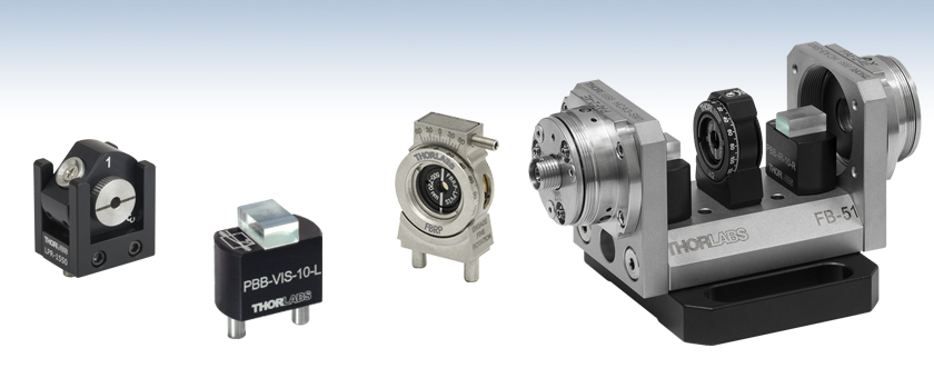
- Polarization Optics Modules Designed for FiberBench Systems
- Interchangeable Modules Maintain Optical Axis Height
- Polarizers Available for Visible through Mid-IR
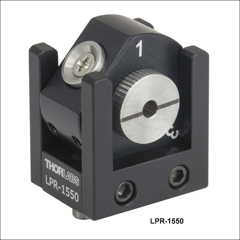
LPR-1550
Linear Polarization
Reference Module
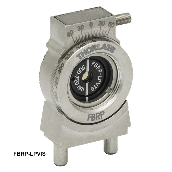
FBRP-LPVIS
Precision Rotating Linear
Polarizer Module
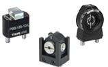
PBB-VIS-10-L
Beam Displacer Module
Application Idea
Variable Optical Attenuator Constructed Within a FiberBench System (See Applications Tab)


Please Wait

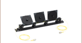
Thorlabs offers several polarization modules that can be used with our FiberBenches. Each module has two dowel pins on its base that precisely align it on a FiberBench. The Rotating Linear Polarizer Modules are made from nanoparticle film polarizers held in FiberBench Rotation Mounts that allow the user to easily adjust the polarization state and are designed for wavelengths from 500 nm to 5.0 µm. The LPR1550 Linear Polarization Reference Module is ideal for use in PM fiber alignment, polarimetry, and extinction ratio measurements. The left-/right-handed Beam Displacer Modules consist of an AR-coated Calcite crystal on a static mounting base. They are designed to displace the horizontal polarization for a variety of wavelength ranges. For more information, please contact Tech Support.
| Fiber Polarization Management Selection Guide | |||||
|---|---|---|---|---|---|
| Polarization Controllers | Linear Polarizers | ||||
 |
 |
 |
 |
 |
 |
| Paddle Operated | In-Line Manual Fiber Polarization Controller |
Free-Space FiberBench | In-Line Package | Polarizing Fiber | Free-Space FiberBench Modules |
| FiberBench Accessories | |||
|---|---|---|---|
| FiberPorts | Optic Mounts | Alignment Tools | Polarizers |
| Beamsplitter Modules | Mirror Modules | Rotating Wave Plates | FiberBenches |
Rotating Linear Polarizer Modules
| Item # Suffix | Wavelength | Transmission | Extinction Ratioa | Damage Threshold | Alignment Accuracya |
|---|---|---|---|---|---|
| -LPVIS | 500 - 720 nm | >65% | >40 dB (10 000:1) | 1 W/cm2 (Continuous Block) 5 W/cm2 (Continuous Pass) |
±3° (Typical) |
| -LPNIR | 650 - 2000 nm | >76% | >30 dB (1 000:1) | 1 W/cm2 (Continuous Block) 5 W/cm2 (Continuous Pass) |
|
| 750 - 1800 nm | >80% | >40 dB (10 000:1) | |||
| 850 - 1600 nm | >82% | >50 dB (100 000:1) | |||
| -LPMIR | 1.5 - 5.0 µm | >35% | >30 dB (1 000:1) | 10 W/cm2 (Continuous Block) 25 W/cm2 (Continuous Pass) |
|
| 2.0 - 4.5 µm | >65% | >40 dB (10 000:1) |
Linear Polarization Reference Module
| Item # | Wavelength | Transmission | Extinction Ratioa |
|---|---|---|---|
| LPR-1550 | 1500 - 1600 nm | >98% | >40 dB |
Calcite Beam Displacer Modules
| Item # | Wavelength | Transmission | Extinction Ratioa |
|---|---|---|---|
| PBB-VIS-10-L | 620 - 690 nm | >96% | >50 dB |
| PBB-VIS-10-R | 620 - 690 nm | >96% | >50 dB |
| PBB-NIR-10-L | 770 - 870 nm | >97% | >50 dB |
| PBB-NIR-10-R | 770 - 870 nm | >97% | >50 dB |
| PBB-YAG-10-L | 970 - 1080 nm | >97% | >50 dB |
| PBB-YAG-10-R | 970 - 1080 nm | >97% | >50 dB |
| PBB-IR-10-L | 1280 - 1625 nm | >97% | >50 dB |
| PBB-IR-10-R | 1280 - 1625 nm | >97% | >50 dB |
Click to Enlarge
Variable Optical Attenuator
| Item #a | Qty | Description |
|---|---|---|
| FB-51W | 1 | Single-Axis FiberBench |
| HCA3 | 2 | FiberBench Wall Plate |
| - | 2 | FiberPort Collimator/Coupler |
| - | 1 | Calcite Beam Displacer (Left-Handed)b |
| - | 1 | Calcite Beam Displacer (Right-Handed)b |
| - | 1 | Rotating Half-Wave Plate |
| - | 2 | SM or PM Fiber Patch Cable |
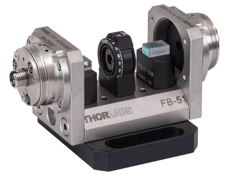
Variable Optical Attenuator Application
A continuously variable attenuator can be assembled using the FiberBench components listed in the table to the right. Since a variety of AR coatings and connectors are available, we recommend selecting individual components suited to your application.
The FiberPort collimates the beam from a SM or PM fiber, and the collimated beam then goes through a calcite beam displacer (walk-off polarizer) where it is split into its respective horizontal (P) and vertical (S) components. The orientation of the wave plate controls how much energy is in the beam. It can be rotated to give the desired attenuation - zero, partial, or full. The signal then enters a reversed beam displacer where it will be recombined or further separated. The only energy that will couple back into the output fiber is the signal on the central axis. The central beam will then be focused into the output fiber by the output FiberPort.
Click to Enlarge
The half-wave plate is rotated so that there is only one output beam; this also means that the input and output polarizations are the same.
Click to Enlarge
The half-wave plate is rotated so that there are three output beams. Its orientation will control how much energy is in each beam. The only energy that will couple into the fiber is the energy in the central beam. The attenuation range is 1 to 40 dB with any value in-between.
Click to Enlarge
The half-wave plate is rotated so that there are two output beams, which will be displaced to the left and to the right of the center. In this position, there will be minimal coupling efficiency, resulting in a maximum attenuation of 40 dB.
Click to Enlarge
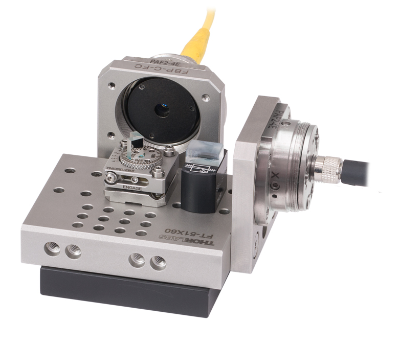
Polarization Beamsplitter
Polarization Splitter
A polarization splitter can be assembled using the components listed in the table below. Since a variety of AR coatings, connectors, and configurations are available, we recommend selecting individual components suited to your application.
The offset (pickoff) mirror is positioned such that it will intersect the displaced beam from the preceding calcite beam displacer (walk-off polarizer) and reflect it by 90°. This combination simplifies the alignment of complex systems by decoupling the reflected beam from the transmitted beam, thus allowing for the independent adjustment of the reflected beam path. Alignment is critical when aligning systems with a walk-off/pickoff combination as clipping can occur if the beam is too large or not centered.
| Item #a | Qty | Description |
|---|---|---|
| FT-51X60 | 1 | Multi-Axis FiberBench |
| HCA3 | 2b | FiberBench Wall Plate |
| - | 2b | FiberPort Collimator/Couplerc |
| - | 1 | Calcite Beam Displacer Module |
| FBT-P01 | 1 | Adjustable Offset Mirror Module |
| - | 2b | SM or PM Fiber Patch Cable |
Click to Enlarge
Diagram of Polarization Splitter Using
Beam Displacer (Right) and Offset Mirror (Left)
Click to Enlarge
Figure 1: An example of how to read a vernier scale. The red arrow indicates what is known as the pointer. Since the tick mark labeled 10 on the vernier scale aligns with one of the tick marks on the main scale, this vernier scale is reading 75.60 (in whatever units the tool measures).
Reading a Vernier Scale
Vernier scales are typically used to add precision to standard, evenly divided scales (such as the scale on Thorlabs' rotation mounts). A vernier scale has found common use in many precision measurement tools, the most common being calipers and micrometers. The direct vernier scale uses two scales side-by-side: the main scale and the vernier scale. The vernier scale has a slightly smaller spacing between its tick marks (10% smaller than the main). Hence, the lines on the main scale will not line up with all the lines on the vernier scale. Only one line from the vernier scale will match well with one line of the main scale, and that is the trick to reading a vernier scale.
Figures 1 through 3 show a vernier scale system for three different situations. In each case, the scale on the left is the main scale, while the small scale on the right is the vernier scale. When reading a vernier scale, the main scale is used for the gross number, and the vernier scale gives the precision value. In this manner, a standard ruler or micrometer can become a precision tool.
The 0 on the vernier scale is the "pointer" (marked by a red arrow in Figs. 1 - 3) and will indicate the main scale reading. In Figure 1 we see the pointer is lined up directly with the 75.6 line. Notice that the only other vernier scale tick mark that lines up well with the main scale is 10. Since the vernier 0 lines up with the main scale’s 75.6, the reading from Figure 1 is 75.60 (in whatever units the tool measures in).
That is essentially all there is to reading a vernier scale. It's a very straightforward way of increasing the precision of a measurement tool. To expound, let’s look at Figure 2. Here we see that the pointer is no longer aligned with a scale line, instead it is slightly above 75.6, but below 75.7; thus the gross measurement is 75.6. The first vernier line that coincides with a main scale line is the 5, shown with a blue arrow. The vernier scale gives the final digit of precision; since the 5 is aligned to the main scale, the precision measurement for Figure 2 is 75.65.
Since the vernier scale is 10% smaller than the main scale, moving 1/10 of the main scale will align the next vernier marking. This asks the obvious question: what if the measurement is within the 1/10 precision of the vernier scale? Figure 3 shows just this. Again, the pointer line is in between 75.6 and 75.7, yielding the gross measurement of 75.6. If we look closely, we see that the vernier 7 (marked with a blue arrow) is very closely aligned to the main scale, giving a precision measurement of 75.67. However, the vernier 7 is very slightly above the main scale mark, and we can see that the vernier 8 (directly above 7) is slightly below its corresponding main scale mark. Hence, the scale on Figure 3 could be read as 75.673 ± 0.002. A reading error of about 0.002 would be appropriate for this tool.
As we've seen here, vernier scales add precision to a standard scale measurement. While it takes a bit of getting used to, with a little practice, reading these scales is fairly straightforward. All vernier scales, direct or retrograde, are read in the same fashion.
Click to Enlarge
Figure 2: An Example of a vernier scale. The red arrow indicates the pointer and the blue arrow indicates the vernier line that matches the main scale. This scale reads 75.65.
Click to Enlarge
Figure 3: An Example of a vernier scale. The red arrow indicates the pointer and the blue arrow indicates the vernier line that matches the main scale. This scale reads 75.67, but can be accurately read as 75.673 ± 0.002.
| Posted Comments: | |
Brian Petro
(posted 2022-07-28 13:55:33.017) Do these beam displacers come unmounted? I would like to put them on the Thorlabs FBTC rotation mounts through an adapter. jgreschler
(posted 2022-08-08 09:06:16.0) Thank you for reaching out to Thorlabs. Components can be requested for quote by emailing techsupport@thorlabs.com. I have reached out to you directly to discuss this possibility, as well as alternatives from our catalogue. Mohamed S. Mohamed
(posted 2019-11-25 14:46:22.983) Do you have a rotating linear polarizer fiber bench module with optimized transmission at a wavelength of 475 nm? nbayconich
(posted 2019-11-27 09:52:37.0) Thank you for contacting Thorlabs. We do not have a stock module for this wavelength at the moment however we could provide a custom version. I will reach out to you directly to discuss our custom capabilities. user
(posted 2013-06-25 14:59:10.19) How can I clean the PCB-2.5-1550 polarizer without damaging it? jlow
(posted 2013-06-25 12:35:00.0) Response from Jeremy at Thorlabs: Dust and other loose contaminants can be usually be blown off using canned air. We also have an optic cleaning tutorial available at http://www.thorlabs.com/tutorials.cfm?tabID=26066 that details other cleaning methods as well. jjurado
(posted 2011-03-31 17:57:00.0) Response from Javier at Thorlabs to Benjamin: Thank you for contacting us. The fiber bench components are attached to the bench through a slip fit of the dowel pins into the mounting holes. The diameter of the dowel pins is 0.125" and the mounting hole diameter is 0.126" (+0.001"/-0.000"), which provides a tight fit between these mating parts. As a result, our fiber tables provide a stable support for polarizer modules and a variety of other optical components, and is also suitable for interferometry applications. benju
(posted 2011-03-31 14:46:38.0) How are items fastened/secured to the fiber table? Do they just slot in? Does that provide sufficient stability for interferometry applications? Thanks, Benjamin |

 Zoom
ZoomApplications
- Monitor Polarization Shift Over Time
- Measure Polarization Extinction Ratio
- Create a Variable Beamsplitter
- Nanoparticle Film Polarizers Mounted in FiberBench-Compatible Housing
- >10 000:1 Extinction Ratio
- 360° Continuous Rotation
- Engraved Scale with 2° Increments
- Ø2.5 mm Clear Aperture for FBR-LPVIS and FBR-LPNIR
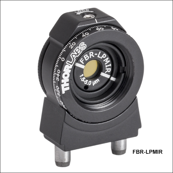
- Ø4.0 mm Clear Aperture for FBR-LPMIR
- Custom Mounts are Available by Contacting Tech Support
Thorlabs' FiberBench Rotating Linear Polarizer Modules utilize a thin layer of sodium-silicate polarizer mounted in FBR Rotation Mounts. These modules absorb light that is not aligned to the transmission axis of the polarizer and are designed for the 500 - 720 nm, 650 - 2000 nm, or 1.5 - 5.0 µm wavelength range. These polarizers provide an excellent extinction ratio of >10 000:1 over most of their specified wavelength range (see Specs tab for details). The transmission axis is marked by the engraved line on the front of the polarizer cells.
The mount for these polarizers features a rotating cell with a knurled edge and a 360° laser-engraved scale marked at 2° increments. A convenient top-located setscrew (0.050" hex) secures the rotational position of the optic cell.
These modules are ideal for a variety of polarimetry applications. Rotating linear polarizers can be used to monitor the polarization of a beam whose polarization state may shift over time due to temperature or other factors; the rotating polarizer can then be adjusted to maintain maximum transmission. A rotating polarizer can measure the polarization extinction ratio of another polarizer element without having to realign components in between measurements. Also, a variable beamsplitter can be constructed using a polarizer module in conjunction with a Beam Displacer Module (sold below).
The FBR mount can be coupled with an FBA post-mountable adapter for use in other applications. The mount is SM05 threaded and the removable polarizer cell is held in the mount with an SM05 retaining ring for holding Ø1/2" optics (SM05RR). The polarizer cells in these modules are also compatible with other Ø1/2" optic mounts. When replacing a polarizer in the mount, be sure to align the engraving on the polarizer with the 0° engraving on the scale. Please note that the thin film in these polarizers is very delicate and should not be touched.
For applications requiring high precision, see the Precision Rotating Linear Polarizer Modules below.

 Zoom
ZoomApplications
- Monitor Polarization Shift Over Time
- Measure Polarization Extinction Ratio
- Create a Variable Beamsplitter
- Nanoparticle Film Polarizers Mounted in FiberBench-Compatible Housing
- >10 000:1 Extinction Ratio
- 360° Continuous Rotation
- Engraved Scale with 2° Increments; Vernier Scale with 10 arcmin Resolution
- ±5.5° Fine Adjustment
- Ø2.5 mm Clear Aperture for FBRP-LPVIS and FBRP-LPNIR
- Ø4.0 mm Clear Aperture for FBRP-LPMIR
- Custom Mounts are Available by Contacting Tech Support
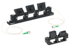
Thorlabs' FiberBench Precision Rotating Linear Polarizer Modules utilize a thin layer of sodium-silicate polarizer mounted in FBRP Rotation Mounts. These modules absorb light that is not aligned to the transmission axis of the polarizer and are designed for the 500 - 720 nm, 650 - 2000 nm, or 1.5 - 5.0 µm wavelength range. These polarizers provide an excellent extinction ratio of >10 000:1 over most of their specified wavelength range (see Specs tab for details). The transmission axis is marked by the engraved line on the front of the polarizer cells.
The mount for these polarizers features a rotating cell with a knurled edge and a 360° laser-engraved scale marked at 2° increments as well as a Vernier scale for determining angular position with a resolution of 10 arcmin. The mount also includes a fine adjustment actuator, which provides ±5.5° of precise angular adjustment with a resolution of 0.48° (28.8 arcmin) per revolution of the screw. After fastening the engagement screw with a 0.028" hex key, the cell can be precisely positioned by turning the actuator at the top of the part with a 0.050" hex key.
These modules are ideal for a variety of polarimetry applications. Rotating linear polarizers can be used to monitor the polarization of a beam whose polarization state may shift over time due to temperature or other factors; the rotating polarizer can then be adjusted to maintain maximum transmission. A rotating polarizer can measure the polarization extinction ratio of another polarizer element without having to realign components in between measurements. Also, a variable beamsplitter can be constructed using a polarizer module in conjunction with a Beam Displacer Module (sold below).
The FBRP mount can be coupled with an FBA post-mountable adapter for use in other applications. The mount is SM05 threaded and the removable polarizer cell is held in the mount with a stainless steel SM05 retaining ring for holding Ø1/2" optics (POLARIS-SM05RR). The polarizer cells in these modules are also compatible with other Ø1/2" optic mounts. When replacing a polarizer in the mount, be sure to align the engraving on the polarizer with the 0° engraving on the scale. Please note that the thin film in these polarizers is very delicate and should not be touched.


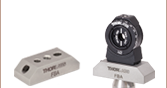
 Zoom
Zoom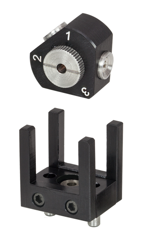
Click for Details
Four Available Orientations (Fourth orientation not shown)
Applications
- Polarization Extinction Ratio Measurements
- Polarimetry
- PM Fiber Alignment
- See the Applications Tab
- Precision Linear Polarization Reference
- 0°, 45°, 90°, and 135° Orientations
- Angle Tolerance <30 arcmin
- Highly Repeatable Positioning by Magnetic Contact
- Wavelength Range: 1510 - 1590 nm
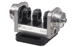
The Linear Polarization Reference Module consists of a Linear Polarizer held in a capture cage. The polarizer is set in the silver wheel on the front of the module, seen on the left, and can be rotated by adjusting the setscrew using a 0.035" hex key.
To use the module, place the front of the module into the cage facing your source with the 1 located at the top. Rotate the front wheel so that it matches the polarization of your source, and tighten the setscrew using a 0.035" hex key, located on the face to the left of the 2. This corresponds to a 0° rotation with respect to the input polarization. From here, the module can be easily positioned to the 2, 3, or 4 settings, which correspond to a 90°, 45°, and 135° clockwise shift of the input polarization, respectively. Position 4 is achieved by flipping the module; the wheel on this side of the housing does not rotate the polarizer but can be adjusted for use as a reference.
Please note that this linear polarization reference module does not incorporate a quarter-wave plate. However, other wavelengths and units with an integrated quarter-wave plate (to function as a manual polarimeter) are available by request. Please contact Tech Support for details.

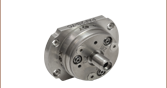
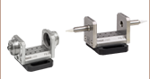
 Zoom
ZoomApplications
- Create Multilevel Optical Systems
- Use in Conjunction with Mirror Modules to Pick Off
Displacement Beam in Custom Optical Systems - Variable Optical Attenuator
- Polarization Splitter
- See the Applications Tab

- AR-Coated Calcite Polarizer
- 100 000:1 Extinction Ratio
- Broadband Operation
- Clear Aperture: 6.0 mm x 3.5 mm
- 500 W/cm2 Power Handling
- Input Diameter: 1 mm (Max)
- Beam Displacement: 1 mm
- Surface Quality: 40-20 Scratch-Dig
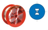
- Please See the Specs Tab for More Details
Each Beam Displacer Module consists of an AR-coated Calcite crystal mounted on a static base so that it can be inserted at the correct height into a FiberBench setup. It is primarily designed to displace the horizontal polarization state by 1 mm. The beam displacing polarizers listed below are designed for use in different wavelength ranges (Visible, NIR, YAG, or IR), offering both left- and right-handed orientations. We also offer calcite beam displacers in round Ø1" housings, available here.