 Products Home
FiberBench Optic Mounts & Wall Plates
- Integrate Optical Components into FiberBenches
- Static, Tip/Tilt, and Rotational Mounting Options
- Easily Interchange Modules While Maintaining Optical Axis Height
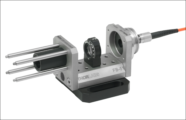
Application Idea
FiberBench Supporting Linear
Polarizer and FT-EOMA Bracket
with EO Modulator Installed
HCA3
Wall Plate
FBS05
Ø1/2" Lens Tube Mount
FBRP
Precision Rotation Mount
FBTC
Tip/Tilt and Rotation Mount for 5 mm Beamsplitter Cubes
CPFB
30 mm Cage System Mount


Please Wait

Thorlabs offers several component modules that can be used to mount numerous precision optical components. These modules can then be easily integrated into a FiberBench system, and position optics at a consistent beam height of 0.56" (14.2 mm). In each case, the module is designed with two steel dowel pins on its underside that fit into the receiving holes on the FiberBench. Once inserted, the design of the mount ensures that the optic will be at the appropriate height for use within the free-space subsystem.
FiberBench Components Featured Below:
| FiberBench Accessories | |||
|---|---|---|---|
| FiberPorts | Optic Mounts | Alignment Tools | Polarizers |
| Beamsplitter Modules | Mirror Modules | Rotating Wave Plates | FiberBenches |
Reading a Vernier Scale on a Linear Main Scale
Vernier scales are typically used to add precision to standard, evenly divided scales (such as the scales on Thorlabs' rotation, goniometric, or translation mounts). A vernier scale has found common use in many precision measurement instruments, the most common being calipers and micrometers. The vernier scale uses two scales side-by-side: the main scale and the vernier scale. The direct vernier scale has a slightly smaller spacing between its tick marks owing to the vernier scale having N ticks for every N - 1 ticks on the main scale. Hence, the lines on the main scale will not line up with all the lines on the vernier scale. Only one line from the vernier scale will match well with one line of the main scale, and that is the trick to reading a vernier scale.
Figures 1 through 3 show a linear vernier scale system for three different situations. In each case, the scale on the left is the main scale, while the small scale on the right is the vernier scale. When reading a vernier scale, the main scale is used for the gross number, and the vernier scale gives the precision value. In this manner, a standard ruler or micrometer can become a precision instrument.
The 0 on the vernier scale is the "pointer" (marked by a red arrow in Figures 1 - 5) and will indicate the main scale reading. In Figure 1 we see the pointer is lined up directly with the 75.6 line. Notice that the only other vernier scale tick mark that lines up well with the main scale is 10. Since the pointer lines up with the main scale’s 75.6, the reading from Figure 1 is 75.60 (in whatever units the instrument measures).
That is essentially all there is to reading a vernier scale. It's a very straightforward way of increasing the precision of a measurement instrument. To expound, let’s look at Figure 2. Here we see that the pointer is no longer aligned with a line on the main scale, but instead it is slightly above 75.6 and below 75.7; thus, the gross measurement is 75.6. The first vernier line that coincides with a main scale line is the 5, shown with a blue arrow. The vernier scale gives the final digit of precision; since the 5 is aligned to the main scale, the precision measurement for Figure 2 is 75.65.
Since this vernier scale is 10% smaller than the main scale, moving the vernier scale by 1/10 of the main scale will align the next vernier marking. This asks the obvious question: what if the measurement is within the 1/10 precision of the vernier scale? Figure 3 shows just this. Again, the pointer line is in between 75.6 and 75.7, yielding the gross measurement of 75.6. If we look closely, we see that the vernier scale 7 (marked with a blue arrow) is very closely aligned to the main scale, giving a precision measurement of 75.67. However, the vernier scale 7 is very slightly above the main scale mark, and we can see that the vernier scale 8 (directly above 7) is slightly below its corresponding main scale mark. Hence, the scale on Figure 3 could be read as 75.673 ± 0.002. A reading error of about 0.002 would be appropriate for
this instrument.
Click to Enlarge
Figure 1: An example of how to read a vernier scale. The red arrow indicates what is known as the pointer. Since the tick mark labeled 10 on the vernier scale aligns with one of the tick marks on the main scale, this vernier scale is reading 75.60 (in whatever units the instrument measures).
Click to Enlarge
Figure 2: The red arrow indicates the pointer and the blue arrow indicates the vernier line that matches the main scale. This scale reads 75.65.

Click to Enlarge
Figure 3: The red arrow indicates the pointer, and the blue arrow indicates the vernier line that matches the main scale. This scale reads 75.67 but can be accurately read as
75.673 ± 0.002.
Reading a Vernier Scale on a Rotating Main Scale
The vernier scale may also be used on rotating scales where the main scale and vernier scale do not share units. Figures 4 and 5 show a vernier scale system for two different situations where the main scale is given in degrees and the vernier scale has ticks every 5 arcmin (60 arcmin = 1°). In each case, the scale on the top is the main scale, while the small scale on the bottom is the vernier scale.
In Figure 4 we see the pointer is lined up directly with the 341° line. Notice that the only other vernier scale tick marks that line up well with the main scale are ±60 arcmin. Since the pointer lines up with the main scale at 341°, the reading from Figure 4 is 341.00°.
There are two ways to determine the reading if the zero on the vernier scale line is between two lines of the main scale. For the first method, take the line on the left side of the pointer on the vernier scale and subtract that value (in arcmin) from the value on the main scale that is to the right on the main scale. As an example, in Figure 5 the vernier pointer is between 342° and 343°; using the left blue arrow of the vernier scale results in
As we've seen here, vernier scales add precision to a standard scale measurement. While it takes a bit of getting used to, with a little practice, reading these scales is fairly straightforward. Vernier scales, whether they are direct or retrograde*, are read in the same fashion.
*A retrograde vernier scale has a larger spacing between its tick marks with N ticks for every N + 1 ticks on the main scale.

Click to Enlarge
Figure 4: An example of a vernier scale where the main scale and the vernier scale are in different units (degrees and arcmins, respectively). The red arrow indicates the pointer. This scale reads 341.00°.
Click to Enlarge
Figure 5: The red arrow indicates the pointer and the blue arrows give the precision value from the vernier scale.
This scale reads 342.75°.
| Posted Comments: | |
user
(posted 2019-11-29 07:55:19.647) Hello, I have a question about FBTP.
Let me inform what are the maximum and minimum thickness of which a plate can be mounted.
I'd like to mount a 1.05 mm thick plate object, is it possible? llamb
(posted 2019-12-03 10:24:44.0) Thank you for your feedback. Since the FBTP requires epoxy to mount a plate optic, there is no minimum thickness requirement. The slot is manufactured to a minimum width of 1.092 mm, so we would recommend 1.09 mm as a very maximum thickness. Your 1.05 mm thick plate will indeed fit. Gabriel Puebla-Hellmann
(posted 2019-10-22 09:04:35.32) Is it possible to get the FBTP without the Dowel Pins? YLohia
(posted 2019-10-22 11:42:04.0) Thank you for contacting Thorlabs. Custom items can be requested by emailing techsupport@thorlabs.com. I have reached out to you directly to discuss the possibility of offering this. anthony.horton
(posted 2017-05-30 15:40:08.097) FiberBench/FiberPort compatible diaphragm shutter?
We have a optical system supplied by a 3rd party vendor and we'd like to add a diaphragm shutter to the output. The output is via a PAFA-X-4-A FiberPort mounted on a HCA3 end plate on the end of an FT-51X76 FiberBench. Unfortunately there don't seem to be any FibreBench/FibrePort compatible diaphragm shutters. The SHB025 1/4" shutter seems almost ideal, except it is slightly larger than the aperture in the HCA3 and there are no adaptors for attaching it to the FiberBench. Is there a solution using existing parts, or plans to introduce one?
Photo of the system into which we want to add the shutter: https://drhotdog.smugmug.com/Other/Laser-comb/n-nj2wRX/i-sRGGrj3/A (the output is on the right) tfrisch
(posted 2017-06-22 09:02:52.0) Hello, thank you for contacting Thorlabs. It looks like you have already been in contact with our Tech Support Team about SHB025 mounted in SHCP025 which can be mounted to the end of a fiber bench using HCA3-CP. hyub.lee
(posted 2016-11-25 16:59:04.833) Hello. I have a question about Kinematic FiberBench Tip/Tilt Rotation Mount for 12.7 mm × 1 mm (W × T) Plate Optics. I'd like to purchase the product for longpass(or shortpass) dichroic mirror mounting.(e.g. DMLP950R) I am using a fiber-bench with two inputs(976nm, and 500-700 nm) and one output, which is a T-shape fiber-bench system, and I want to install DMLP950R into it using this rotation mount. I think the thickness of DMLP950R is suitable to be installed (1mm), but H x W is 36 x 25 mm, which is larger than 12. 7mm. However, I think if the mirror is installed although the mirror size is larger than 12.7mm, I'd like to buy it. Can you advise about this issue? Thanks. tfrisch
(posted 2016-11-30 10:11:04.0) Hello, thank you for contacting Thorlabs. We can offer custom sizes of dichroic mirrors that will fit in our FiberBench compatible mounts. Our Tech Support staff will contact you directly with a quote. |

 Zoom
Zoom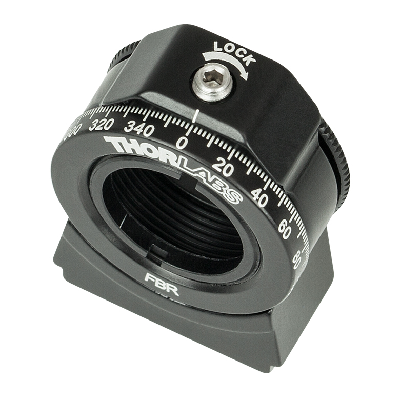
Click to Enlarge
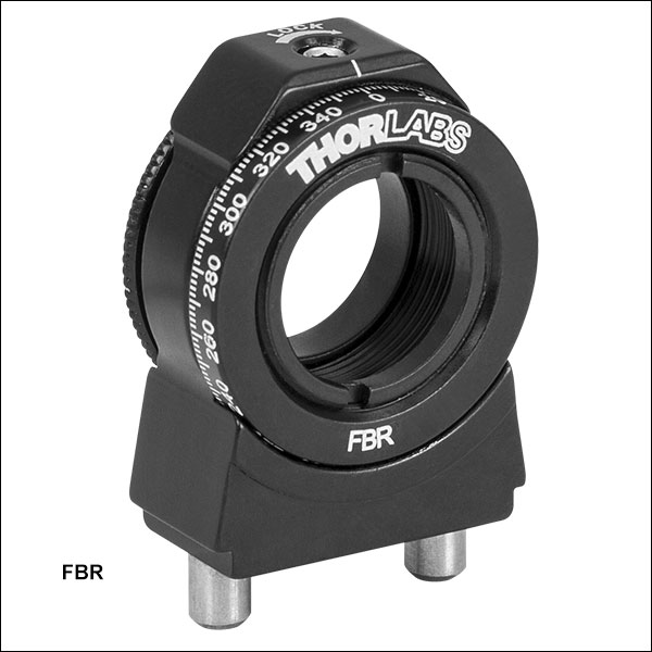
The FBR mount has a rotation lock screw (0.050" hex) and engraved scale with 2° increments.

- Continuous 360° Rotation with Locking Setscrew
- Direct Read 2° Graduations Engraved on the Edge of the Rotation Dial
- Mount Ø1/2" (Ø12.7 mm) Optics up to 0.17" (4 mm) Thick
- Ø0.45" (Ø11.4 mm) Clear Aperture
- SM05-Threaded (0.535"-40) for Compatibility with Ø1/2" Lens Tubes
- Optics Secured with Included SM05RR Retaining Ring
The FBR FiberBench-compatible rotation mount has a knurled edge and 360° laser-engraved scale marked at 2° increments. It is SM05-threaded (0.535"-40) for mounting optics, Ø1/2" lens tubes, and other SM05-threaded components. This mount is ideal for holding our Ø1/2" polarizers and wave plates (when removed from their Ø1" mounting cell). The mount's rotating cell has A convenient top-located setscrew (0.050" hex) secures the rotational position of the stage.

 Zoom
Zoom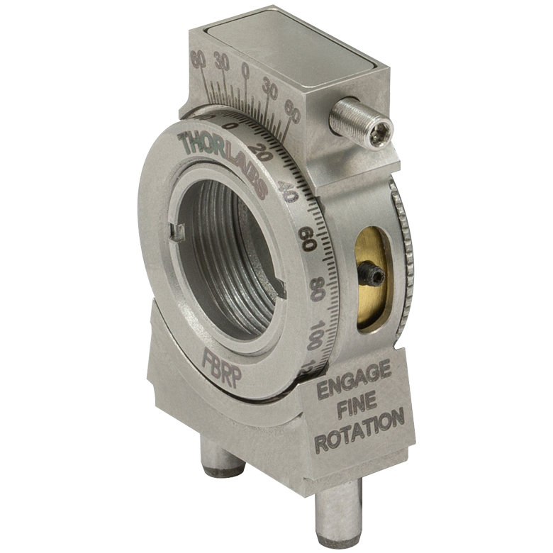
Click to Enlarge
The side of the FBRP mount features an engagement screw (0.028" hex) and actuator (0.050" hex).
Click to Enlarge
Align a waveplate to control the polarization angle between two fibers.
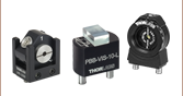
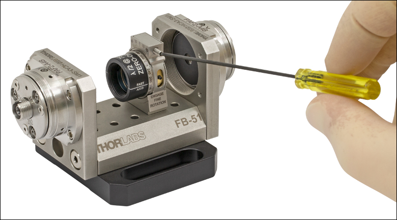
- Continuous 360° Rotation
- Direct Read 2° Graduations Engraved on the Edge of the Rotation Dial
- ±5.5° of Fine Adjuster-Driven Rotation when Engaged
- Vernier Scale with 10 arcmin Resolution
- Mount Ø1/2" (Ø12.7 mm) Optics up to 0.23" (5.8 mm) Thick
- Ø0.43" (Ø10.9 mm) Clear Aperture
- SM05-Threaded (0.535"-40) For Compatibility with Ø1/2" Lens Tubes
- Optics Secured with Included POLARIS-SM05RR Retaining Ring
The FBRP stainless steel, FiberBench-compatible rotation mount. The mount's SM05-threaded (0.535"-40) rotating cell has a knurled edge for coarse positioning. After fastening the engagement screw with a 0.028" hex key, the cell can be precisely positioned by turning the actuator at the top of the part with a 0.050" hex key. As the graduations engraved on the cell are 2°, values read from the vernier scale can be converted to arcmins by multiplying by a factor of two. Mount Ø1/2" optics, Ø1/2" lens tubes, and other SM05-threaded components.
This mount is ideal for holding our Ø1/2" polarizers and wave plates (when removed from their Ø1" mounting cell). We also offer FiberBench Polarization Modules and FiberBench Rotating Wave Plate Modules, which have linear polarizers, quarter-wave plates, or half-wave plates pre-mounted in FBRP rotation mounts.

 Zoom
Zoom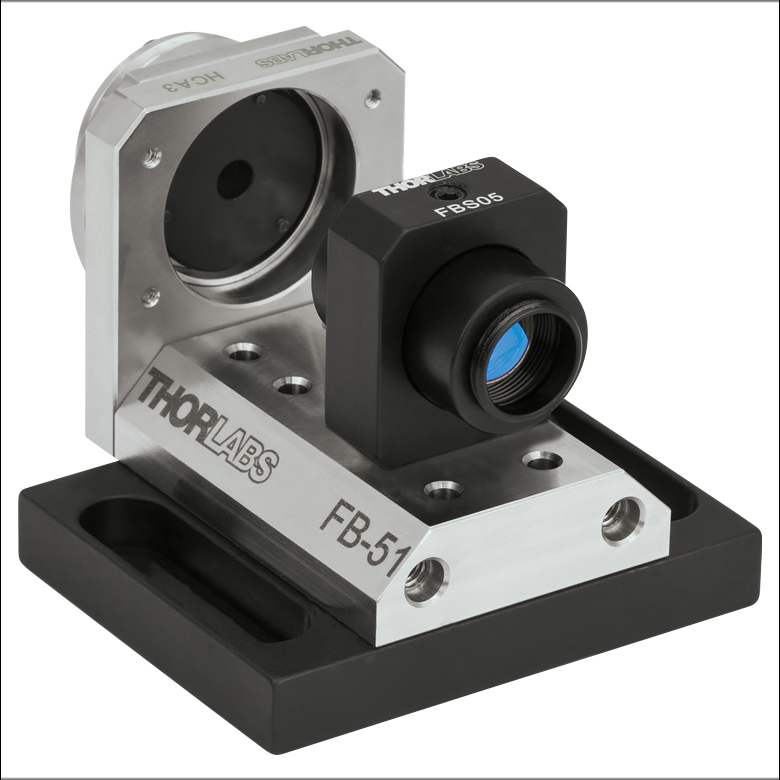
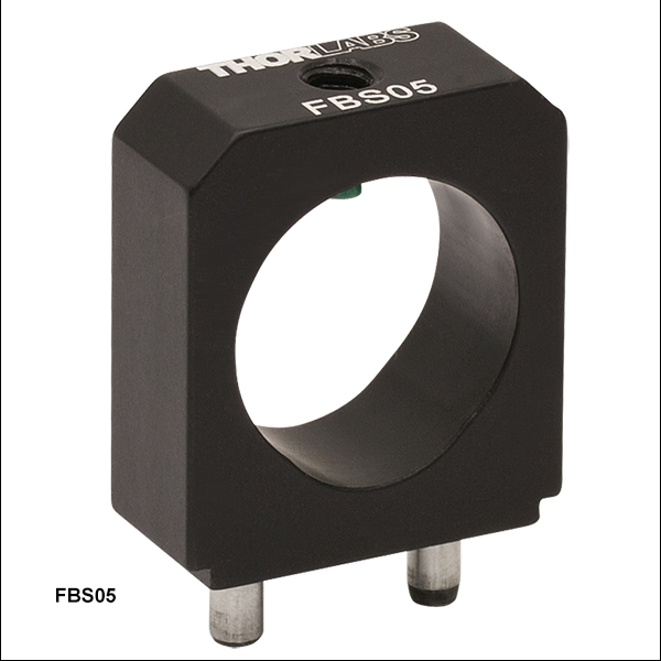
- Mounts a Ø1/2" Lens Tube to a FiberBench
- Nylon-Tipped 8-32 Setscrew for Locking Lens Tube in Place
The FBS05 lens tube mount can hold Ø1/2" lens tubes at a beam height of 0.56" (14.2 mm) and enables the incorporation of Ø1/2" optical elements into the FiberBench system. A Ø1/2" lens tube can slip into the FBS05 and then be locked in place with the nylon-tipped 8-32 setscrew located at the top of the mount. The two dowel pins on the mount easily fit into the receiving holes on any of our Single-Axis or Multi-Axis FiberBenches.

 Zoom
Zoom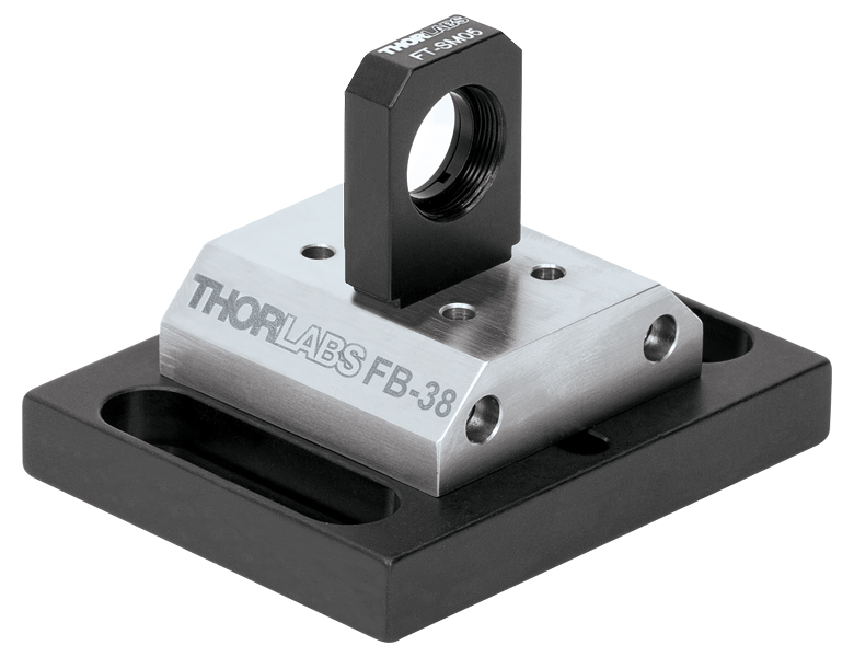
Click to Enlarge
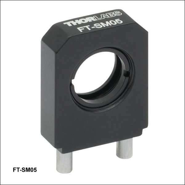
FT-SM05 Optic Mount on an FB-38 FiberBench
- Holds Ø1/2" Optics Up to 3.9 mm Thick*
- SM05 Retaining Ring Included
- Ø11 mm Clear Aperture
The FT-SM05 optics mount is designed to hold Ø1/2" optics (ND filters, diffusers, colored filters, and the VRC2D05 alignment disk) while maintaining the appropriate beam height when placed on a FiberBench. It features our standard SM05 thread (0.535"-40).
*This specification is true for relatively flat lenses. For lenses with small focal lengths, and hence large lens curvatures, please contact Tech Support to ensure a proper fit.

 Zoom
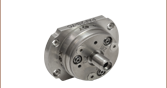
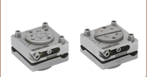
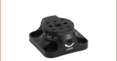
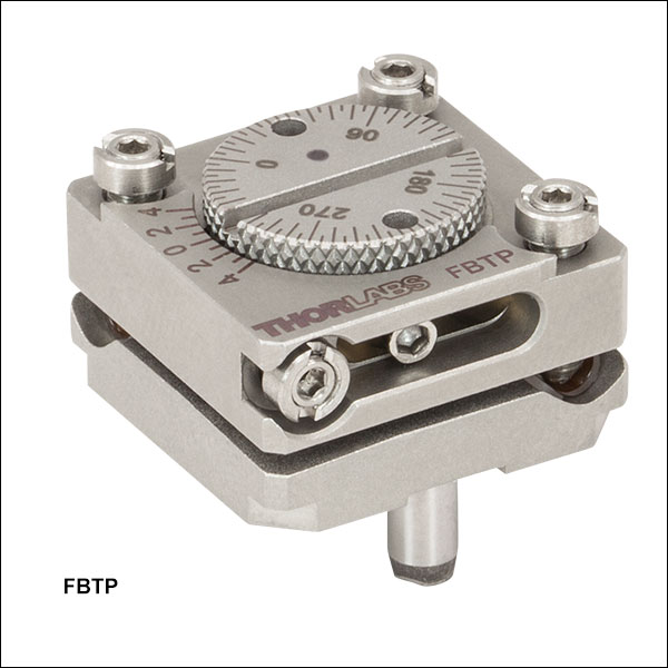
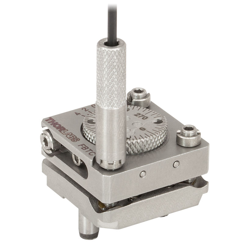
Zoom- Use for 5 mm Cube or 1 mm Thick Plate Optics
- ±3° Tip/Tilt Adjustment via Three M2.5 x 0.2 Precision Adjusters
- 360° Continuous Rotation with ±12° Fine Adjustment
- Four Locking Collars and a Spanner Wrench are Included
- Additional Locking Collars Available Separately
- Please Contact Tech Support for Custom Mounting Options
These tip/tilt rotation FiberBench mounts are designed to mount either 5 mm cube optics, such as polarizing or non-polarizing beamsplitter cubes, (item # FBTC) or 1 mm thick plate optics up to 12.7 mm (0.5") wide, such as beamsplitters or mirrors, (item # FBTP) while maintaining the appropriate beam height. Both versions require epoxy to mount optical components. The circular rotation plate can be rotated a full 360° and is engraved with a scale marked every 5°. Additionally, a Vernier scale provides 1° resolution for fine rotation. These mounts do not suffer from left/right handedness restrictions, and thus can be used in any orientation on a FiberBench.
An engraved dot is present on the FBTP Plate Optic Mount between the 0° and 90° engravings. Beamsplitter optics should be installed with the beamsplitter coating facing this dot. This allows an incident beam to be aligned so that it is split at the center of the mount.
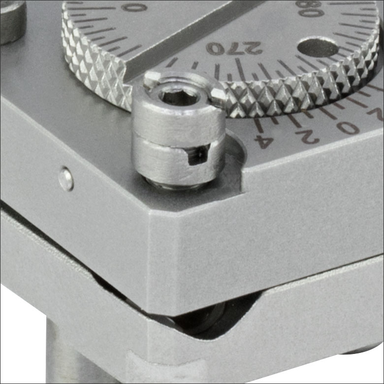
These mounts allow for tip, tilt, and rotational adjustment for precision beam alignment and steering control. Three screws control the tip/tilt of the mount (see Figure 1), yielding up to ±3° of adjustment. Additionally, these screws can also provide some vertical adjustment when all three screws are rotated by the same amount. A physical stop prevents the tip/tilt springs from being overextended. When engaged, the fine rotation adjustment screw (see Figure 1) gives up to ±12° adjustment. All adjustment screws use a 0.05" hex key, which is included with these mounts. Furthermore, they can be locked into position (see Figure 2) with a spanner wrench to prevent accidental movement. The necessary spanner wrench (SPW403) is included; simply insert the included hex key through the spanner wrench, and while holding the adjustment screw static, use the spanner wrench to tighten the locking nut (see Figure 3).
Additional locking collars and spanner wrenches are also available for purchase separately. If desired, two locking collars can be used together to create a hard stop (see Figure 4). Alternatively, a single collar can be epoxied to an adjuster using our G14250 epoxy to create a permanent hard stop.
We also offer post-mountable versions of these mounts with 8-32 (M4) taps for general mounting of optics on Ø1/2" Posts.
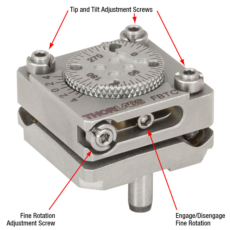
Click to Enlarge
Figure 1: These are the adjuster locations on the FBTC mount. The FBTP has its adjustment screws in the same locations.
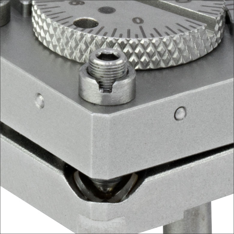
Click to Enlarge
Figure 2: A single locking collar can lock an adjuster in position.
Click to Enlarge
Figure 3: Use the included hex key and spanner wrench to lock an adjustment screw in place.
Click to Enlarge
Figure 4: Two collars can be locked together to create a hard stop.

 Zoom
Zoom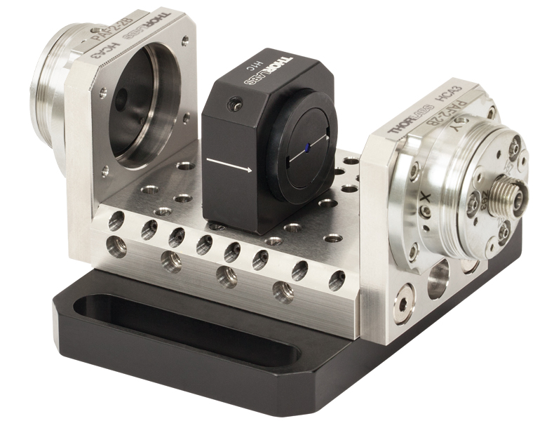
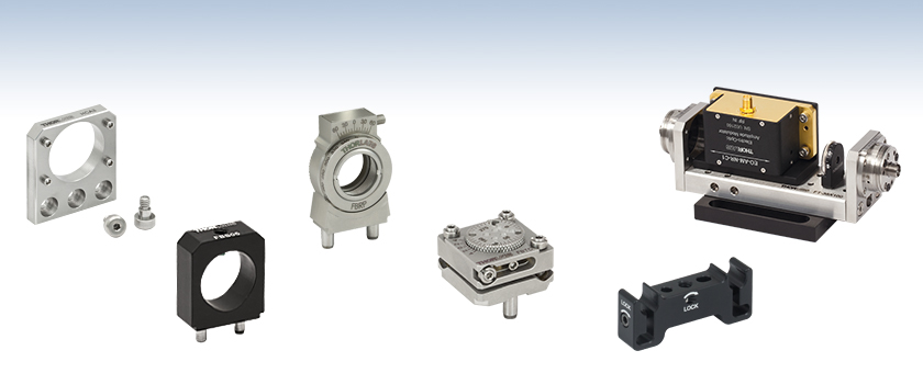
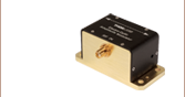
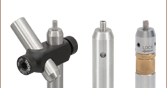
- Mounts Isolators that have a 0.865" Outer Diameter
- Aligns Optical Axis with Free-Space Isolator
This mount secures our Free-Space Isolators with an outer diameter of 0.865" to our FiberBench series, aligning the optical axis with the isolator. The mount is compatible with all of our FiberBenches.
Compatible Isolators:

 Zoom
Zoom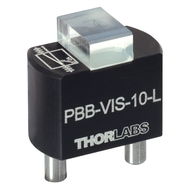
- Use for Fixed Mounting of a Variety of Optical Elements
- Approximately 1.5 mm from Beam Centerline to Top Surface
The HCB Static Mounting Base allows a user-supplied optic to be secured to the top surface with epoxy and then inserted at the correct height into a FiberBench setup. Once inserted into the receiving holes of the FiberBench , the distance from the top surface of the platform to the point at which the source beam will strike the optic is approximately 1.5 mm. The figure to the right shows Thorlabs' PBB Polarizer attached to the HCB base.

 Zoom
Zoom
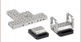
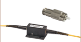
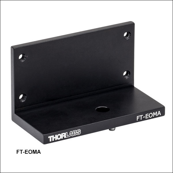
- Adapter Plate Mounts an EO Modulator in the Beam Path
- 4 Tapped Holes for Mounting the Modulator (Screws Included)
- Alignment Pins for Mounting to any FiberBench Over 70 mm Long
- Mounting Screws Included
The FT-EOMA is a mounting bracket used to mount an Electro-Optic (EO) Modulator onto a FiberBench. The length of the bench needs to be at least 70 mm in the direction you wish to mount the modulator. Incorporation of the optional EO Modulator optic mount and polarizer (EO-GTH5M) will require a longer FiberBench. The Linear Polarizer modules are well suited for use with an EO Modulator in a FiberBench System.

 Zoom
Zoom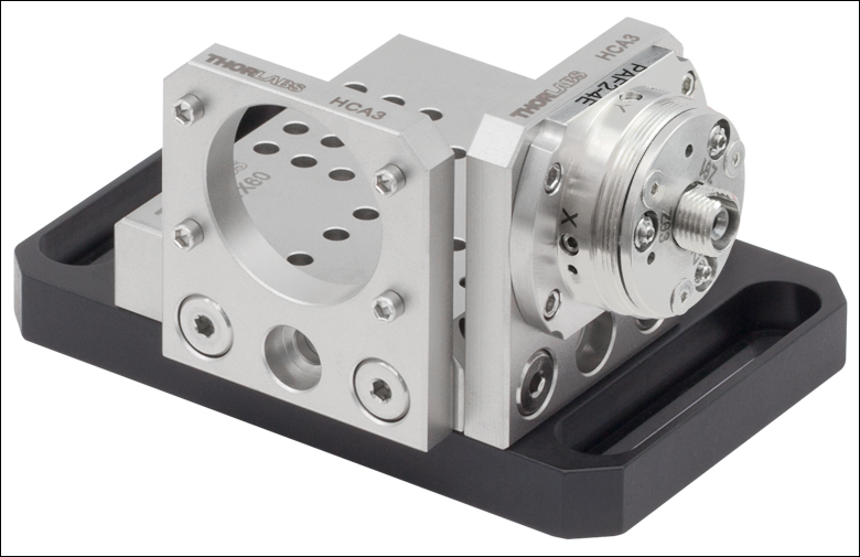
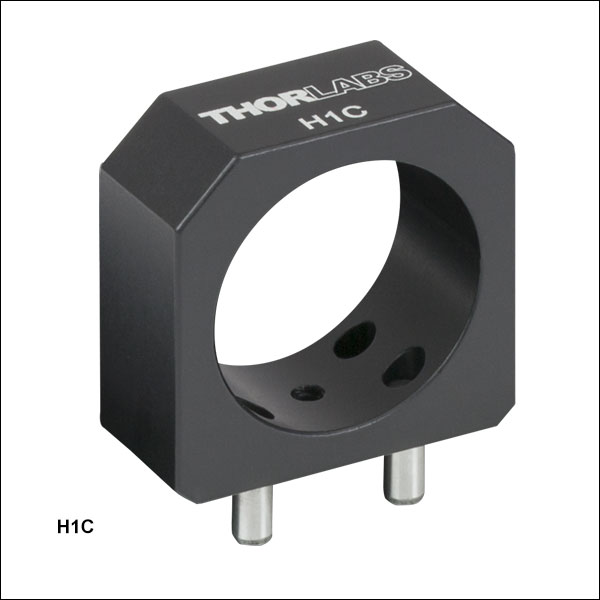
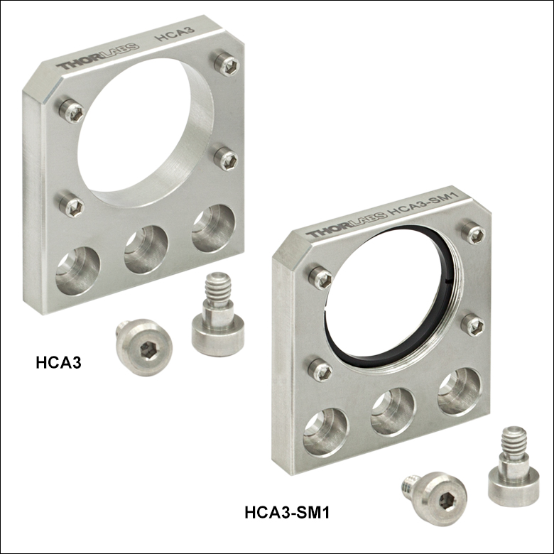
- Mounts to the Edge of Thorlabs' FiberBenches
- HCA3 and HCA3-SM1 Mount a FiberPort Collimator/Coupler
- HCA3-SM1 has an SM1-Threaded (1.035"-40) Port
These Wall Plates can be attached to the sides of a FiberBench using the two included 8-32 mounting screws. The HCA3 and HCA3-SM1 are used to mount FiberPorts to FiberBenches using the four included 2-56 screws (see photo to the right). The HCA3-SM1 is internally SM1 (1.035"-40) threaded for compatibility with our Ø1" Lens Tubes and other SM1-threaded devices such as Thorlabs' Photodetectors. Each wall plate includes screws for mounting to our FiberBenches and the SM-threaded wall plates each include one retaining ring.

 Zoom
Zoom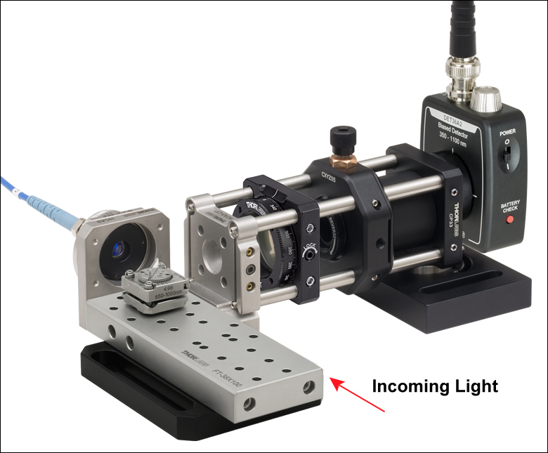
Click to Enlarge
The HCA3-CP is used to combine a FiberBench and a 30 mm Cage System for a power sampling application. A beamsplitter picks off light to a detector and allows the rest of the signal to be coupled into a Fiber Patch Cable using a FiberPort. A polarizer between the beamsplitter and the detector allows the polarization state of light entering the fiber to be monitored.a
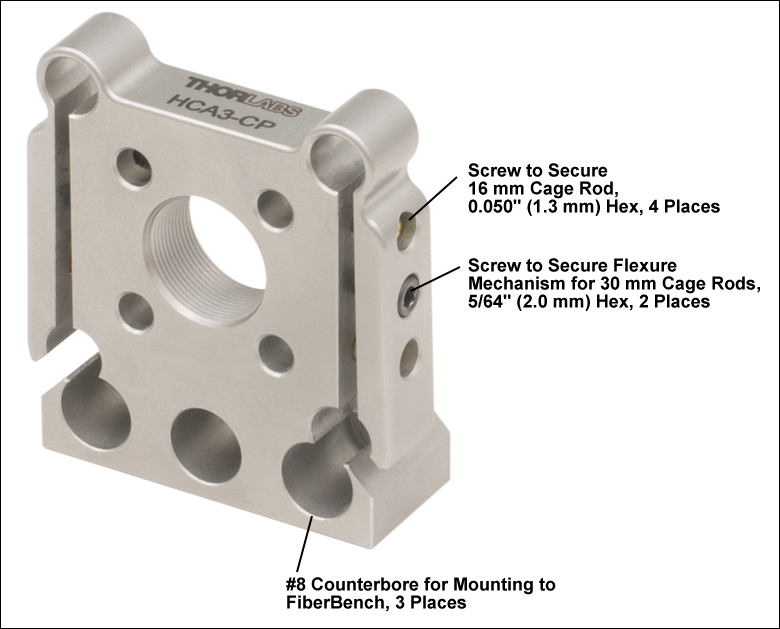
Click for Details
The HCA3-CP FiberBench Adapter Plate accepts cage rods for 16 mm and 30 mm Cage Systems.
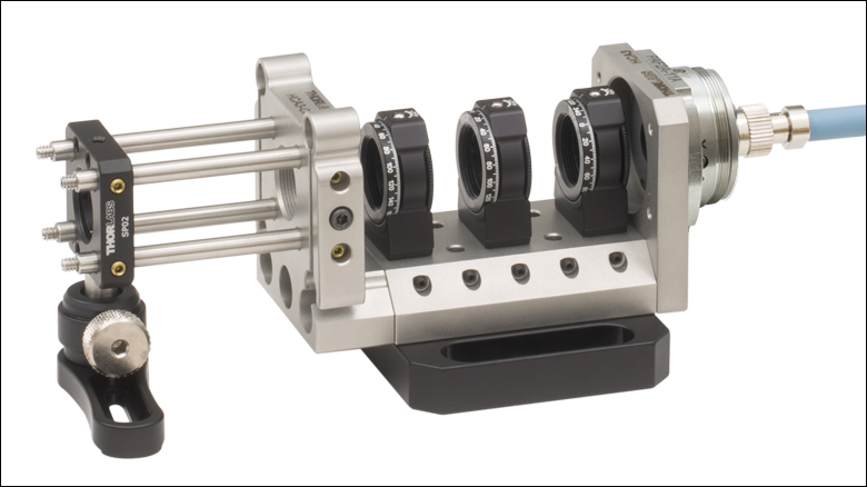
Click to Enlarge Output from a fiber passes through a
FiberBench-based polarization controller before entering a 16 mm cage system through the HCA3-CP.
Click to Enlarge FiberBench with FiberPort, HCA3-SM05 Wall Plate, 16 mm Cage System, and Ø1/2" Lens Tube
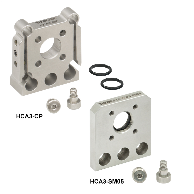
- Mounts to the Edge of Thorlabs' FiberBenches
- HCA3-CP is Compatible with Thorlabs' 16 mm and 30 mm Cage Systems
- HCA3-SM05 has 4-40 Taps to Accept Cage Rods from Thorlabs' 16 mm Cage System
- SM05 (0.535"-40) Thread for Compatibility with Ø1/2" Lens Tubes
These Wall Plates allow FiberBenches to be combined with Thorlabs' Cage Systems. They can be attached to the sides of a FiberBench using the two included 8-32 mounting screws. The HCA3-SM05 features four 4-40 taps and is internally SM05- threaded (0.535"-40) for compatibility with our 16 mm Cage System and Ø1/2" Lens Tubes, respectively (see photo to the right).
The HCA3-CP can accept cage rods for 30 mm and 16 mm cage systems either simultaneously or separately. Three #8 counterbores on the bottom of the plate allow it to be mounted to one of Thorlabs' FiberBenches. The plate accepts Ø4 mm or Ø6 mm cage rods for 16 mm or 30 mm cage systems, respectively. The Ø4 mm cage rods are held in place for by locking screws that accept a 0.05" (1.3 mm) hex key. The Ø6 mm cage rods are secured using a flexure mechanism that can be tightened by a single locking screw on each side of the mount that accepts 5/64" (2.0 mm) hex keys. The port through the center is SM05-threaded, allowing it to accept lens tubes or other threaded optical components.
When combining a FiberBench with a cage system, make sure that the FiberBench is properly supported to avoid applying excess torque to the cage rods. If the cage system is low enough, the FiberBench can rest directly on the optical table. For segments of the cage system that are elevated off of the optical table, the FiberBench can be supported using a Ø1" optical post threaded into the 8-32 or M4 tap in the base.
Each wall plate includes screws for mounting to our FiberBenches. The HCA3-SM05 ships with one SM05RR retaining ring to aid in securing SM05-threaded components, while the HCA3-CP ships with two retaining SM05RR rings to secure unmounted optics up to 0.21" (5.3 mm) thick, such as Thorlabs' Premium Hard-Coated Bandpass Filters.

 Zoom
Zoom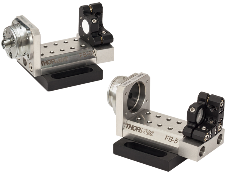
Click for Details
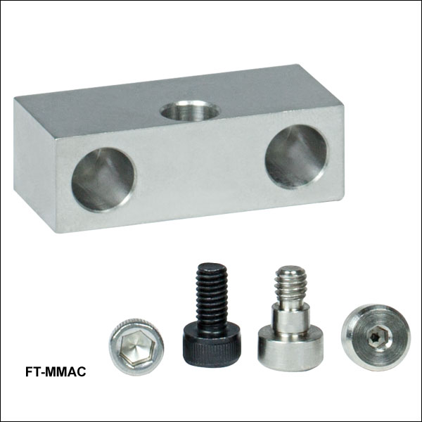
A KS05 mirror mount positioned on a fiber bench with a FT-MMAC.
- For Mounting a Mirror Mount to FiberBench
- Mounting Screws Included
The FT-MMAC is ideal for mounting mirror mounts (or any 8-32 threaded mount) to the side of our FiberBenches. The FT-MMAC comes with all the screws necessary to mount it to the bench (two 8-32 shoulder screws) and to the mirror mount (one 8-32 and one M4). The FT-MMAC can be used to position a wide variety of our precision, smooth bore, or compact mirror mounts. Additionally, users can mount one of our VH1 V-clamps with this versatile adapter.

 Zoom
Zoom
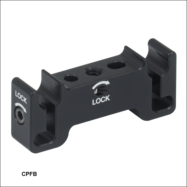
Click to Enlarge
Two FBR FiberBench Rotation Mounts Secured by CPFB Mounts in a 30 mm Cage System
- Mount FiberBench Components in a 30 mm Cage System
- Quick-Release Snap-In Flexure Mechanism for Integration Into 30 mm Cage Systems
- Post Mountable via 8-32 (M4) Tap
This 30 mm Cage System Mount for FiberBench Components allows integration of our line of FiberBench Components with our 30 mm cage system. It includes two through holes that fit the dowel pins on our FiberBench optic mounts. Once the dowels have been inserted, they can be locked in position using a 0.035" balldriver or hex key to tighten the setscrew on the front face of the mount.
The mount includes two snap-in flexure clamps for attaching our Ø6 mm cage rods, which can be locked with a 5/64" (2.0 mm) hex key. This snap-in feature allows components to be easily inserted and removed without disassembling the entire cage system. When this mount is used in a cage system that is attached to a FiberBench with the HCA3-CP cage plate, the beam height for all optical components is the same. An 8-32 (M4) tapped hole on the bottom of the CPFB mount can be used to secure it to a Ø1/2" post. Please note that this cage system mount cannot be used with FiberBench optic mounts that are more than 0.75" (19.1 mm) wide in the direction perpendicular to the optical axis.
| Compatible FiberBench Accessories | ||
|---|---|---|
| Optic Mounts (Compatible with FBR, FT-SM05, FBTP, and HCB) | Alignment Tools | Polarizers |
| Beamsplitter Modules | Mirror Modules | Rotating Wave Plates |

 Zoom
Zoom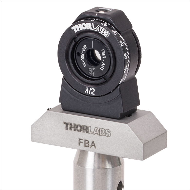
Click to Enlarge
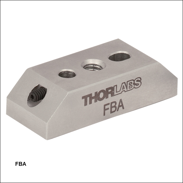
FBR-AH1 on an FBA Post Mounting Adapter
- Use FiberBench Components for Free-Space Applications
- Mount FiberBench Accessories with Dowel Pins to Ø1/2" Posts
- #2-56 Setscrew for Locking Accessory in Place (Hex Key Included)
Thorlabs' FBA (/M) FiberBench Adapter Mounts can be used to secure compatible FiberBench accessories to Ø1/2" Posts. The FBA can be mounted to a Ø1/2" post via the 8-32 (M4) tapped hole that goes through the center of the adapter. This freedom to mount individual pieces to a post gives the user the option of using the compact FiberBench accessories for free space applications.
The adapter is designed to be compatible with FiberBench accessories that have two steel dowel pins on their underside. These pins fit into the receiving holes on the adapter, and the 2-56 setscrew on the side of the adapter can be used to lock the FiberBench accessory in position.
| Compatible FiberBench Accessories | ||
|---|---|---|
| Optic Mounts (Compatible with FBR, FBS05, FT-SM05, FBTP, H1C, and HCB) | Alignment Tools | Polarizers |
| Beamsplitter Modules | Mirror Modules | Rotating Wave Plates |