InGaAs Free-Space Amplified Photodetectors
- Wavelength Ranges Between 800 - 2600 nm
- Maximum Bandwidths up to 1.5 GHz
- Sensitivities Down to Femtowatt Powers
- Fixed and Switchable Gain Versions
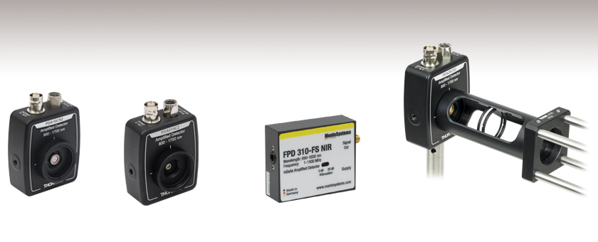
PDA10CS2
Switchable Gain
13 MHz Max Bandwidth
Application Idea
PDA Series Detector with Ø1" Lens Tube Attached to a 30 mm Cage System
PDA015C2
Fixed Gain
380 MHz Max Bandwidth
FPD310-FS-NIR
Switchable Gain
1.5 GHz Max Bandwidth

Please Wait
| Item # | Wavelength Range |
Bandwidth | NEP |
|---|---|---|---|
| Fixed Gain | |||
| PDA015C2 | 800 - 1700 nm | DC - 380 MHz | 20 pW/Hz1/2 |
| PDA05CF2 | 800 - 1700 nm | DC - 150 MHz | 12.6 pW/Hz1/2 |
| PDF10C2 | 800 - 1700 nm | DC - 20 Hz | 7.5 x 10⁻³ pW/Hz1/2 |
| PDA20C2 | 800 - 1700 nm | DC - 5 MHz | 22 pW/Hz1/2 |
| PDA10D2 | 900 - 2600 nm | DC - 25 MHz | 10.1 pW/Hz1/2 |
| FPD510-FS-NIR | 950 - 1650 nm | DC - 250 MHz | 3.2 pW/Hz1/2 |
| FPD610-FS-NIR | 950 - 1650 nm | DC - 600 MHz | 6.6 pW/Hz1/2 |
| Switchable Gain | |||
| PDA20CS2a | 800 - 1700 nm | DC - 11 MHz | 1.95 - 61 pW/Hz1/2 |
| PDA10CS2a | 900 - 1700 nm | DC - 13 MHz | 1.91 - 46 pW/Hz1/2 |
| FPD310-FS-NIRb | 950 - 1650 nm | 1 - 1500 MHz | 14.1 pW/Hz1/2 |
Features
- Wavelength Ranges within 800 to 2600 nm
- Low-Noise Amplification with Fixed or Switchable Gain
- Load Impedances 50 Ω and Higher
- PDF10C2: High Impedance Loads Only
- Menlo Systems' FPD Series Detectors: 50 Ω Output Impedance Only
- Free-Space Optical Coupling
We offer a selection of Indium Gallium Arsenide (InGaAs) Free-Space Amplified Photodetectors that are sensitive to light in the NIR wavelength range. Thorlabs' amplified photodetectors feature a built-in, low-noise transimpedance amplifier (TIA) which, for select detectors, is followed by a voltage amplifier. Menlo Systems' FPD series amplified photodetectors have a built-in radio frequency (RF) or transimpedance amplifier. We offer fixed-gain versions that possess a fixed maximum bandwidth and total transimpedance gain, as well as switchable-gain versions with two or eight gain settings.
Thorlabs' photodetectors are designed to meet a range of requirements, with offerings that include the 380 MHz PDA015C2 with an impulse response of 1 ns, the high-sensitivity PDF10C2 with a noise equivalent power (NEP) of 7.5 fW/Hz1/2, and the switchable-gain PDA20CS2 with eight switchable maximum gain (bandwidth) combinations from 1.51 kV/A (11 MHz) to 4.75 MV/A (3 kHz). The PDF10C2 with femtowatt sensitivity is a low-frequency device that should only be terminated into high impedance (Hi-Z) loads, while all other of our InGaAs PDA amplified photodetectors are capable of driving loads from 50 Ω to Hi- Z.
Click to Enlarge
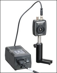
The PDA05CF2 with the Included ±12 V Power Supply. Replacement power supplies are sold below.
Every PDA and PDF detector has internal SM05 (0.535"-40) threading and external SM1 (1.035"-40) threading. Each unit's housing will have either 8-32 threads, M4 x 0.7 threads, or universal mounting holes that accept both 8-32 and M4 x 0.7 threads, and specific information for each detector is provided by clicking on the icon in the Housing Features column of the tables below. For more information on the housings with universal taps, please see the Housing Features tab.
Menlo Systems' FPD series photodetectors are easy-to-use InGaAs-PIN photodiode packages with an integrated high-gain, low-noise RF (FPD310-FS-NIR) or transimpedance (FPD510-FS-NIR and FPD610-FS-NIR) amplifier. The FPD310-FS-NIR is recommended, in particular, for applications like pulse shape and low-noise radio frequency extraction. This photodetector is optimized for high gain, high bandwidths, extremely short rise times, and high signal-to-noise ratio. It has a 0.5 ns rise time and a switchable gain between two settings, allowing for an optimal performance for the user's application. The FPD510-FS-NIR and FPD610-FS-NIR have a fixed gain and are optimized for highest signal-to-noise-ratio for detection of low level optical beat signals at frequencies up to 250 MHz and 600 MHz, respectively. The FPD510-FS-NIR has a rise time of 2 ns, while the FPD610-FS-NIR has a 1 ns rise time. The 3 dB bandwidth of these DC-coupled devices is 200 MHz for the FPD510-FS-NIR and 500 MHz for the FPD610-FS-NIR. The compact design of the FPD detectors allows for easy OEM integration. The housing of each Menlo detector features one M4 tapped hole for post mounting.

Click to Enlarge
Menlo Systems’ Detectors Include a Location-Specific ±12 V Power Supply
Power Supply
A ±12 V linear power supply that supports input voltages of 100, 120, and 230 VAC is included with each amplified photodetector. Replacement power supplies are available separately below. Before connecting the power supply to the mains, ensure that the line voltage switch on the power supply module is set to the proper voltage range. The power supplies should always be powered up using the power switch on the power supply itself. Hot plugging the unit is not recommended.
Menlo's FPD510-FS-NIR, FPD610-FS-NIR and FPD310-FS-NIR include a low-noise power supply.
For detectors with a fiber coupled input, see InGaAs Fiber-Coupled Amplified Photodetectors.
Performance Specifications
| Item # | Wavelength | Bandwidth | Rise Time | Peak Responsivity | Noise Equivalent Power (NEP)a |
Active Area | Operating Temperature Range |
|---|---|---|---|---|---|---|---|
| Fixed Gain | |||||||
| PDA015C2 | 800 - 1700 nm | DC - 380 MHz | 1.0 ns | 0.95 A/W @ 1550 nm | 20 pW/Hz1/2 | 0.018 mm2 (Ø150 µm) | 10 to 40 °C |
| PDA05CF2b | 800 - 1700 nm | DC - 150 MHz | 2.3 ns | 1.04 A/W @ 1590 nm | 12.6 pW/Hz1/2 | 0.2 mm2 (Ø0.5 mm) | 10 to 50 °C |
| PDF10C2 | 800 - 1700 nm | DC - 20 Hz | 19 msc | 1.0 A/W @ 1550 nm | 7.5 x 10⁻³ pW/Hz1/2 | 0.2 mm2 (Ø0.5 mm) | 10 to 50 °C |
| PDA20C2 | 800 - 1700 nm | DC - 5 MHz | 70 ns | 1 A/W @ 1550 nm | 22 pW/Hz1/2 | 3.14 mm2 (Ø2.0 mm) | 10 to 50 °C |
| PDA10D2b | 900 - 2600 nm | DC - 25 MHz | 15 ns | 1.35 A/W @ 2300 nm | 10.1 pW/Hz1/2 | 0.8 mm2 (Ø1.0 mm) | 10 to 50 °C |
| FPD510-FS-NIR | 950 - 1650 nm | DC - 250 MHz | 2 ns | - | 3.2 pW/Hz1/2 | 0.07 mm2 (Ø0.3 mm) | 10 to 40 °C |
| FPD610-FS-NIR | 950 - 1650 nm | DC - 600 MHz | 1 ns | - | 6.6 pW/Hz1/2 | 5 x 10⁻³ mm2 (Ø0.08 mm) | 10 to 40 °C |
| Switchable Gain | |||||||
| PDA20CS2b | 800 - 1700 nm | DC - 11 MHzd | N/Ae | 1.04 A/W @ 1590 nm | 1.95 - 61 pW/Hz1/2 | 3.14 mm2 (Ø2.0 mm) | 10 to 40 °C |
| PDA10CS2b | 900 - 1700 nm | DC - 13 MHzd | N/Ae | 1.05 A/W @ 1550 nm | 1.91 - 46 pW/Hz1/2 | 0.8 mm2 (Ø1.0 mm) | 10 to 40 °C |
| FPD310-FS-NIR | 950 - 1650 nm | 1 - 1500 MHz | 0.5 ns | - | 14.1 pW/Hz1/2 | 5 x 10⁻³ mm2 (Ø0.08 mm) | 10 to 40 °C |
Gain Specifications
Fixed Gain Detectors
| Item # | Gain w/ Hi-Z Load | Gain w/ 50 Ω Load | Offset (±) | Output Voltage w/ Hi-Z Load |
Output Voltage w/ 50 Ω Load |
|---|---|---|---|---|---|
| PDA015C2 | 50 kV/A | 25 kV/A | 20 mV | 0 to 10 Va | 0 to 5 Va |
| PDA05CF2 | 10 kV/A | 5 kV/A | 20 mV | 0 to 10 V | 0 to 5 V |
| PDF10C2b | 1x10⁸ kV/A | - | <75 mV | 0 to 10 V | - |
| PDA20C2 | 500 kV/A | 175 kV/A | 25 mV | 0 to 10 V | 0 to 3.5 V |
| PDA10D2 | 10 kV/A | 5 kV/A | 75 mV (375 mV Max) | 0 to 10 V | 0 to 5 V |
| FPD510-FS-NIR | - | 1.5 x 10⁵ Vpp/Wc 5 x 10⁴ V/Wd |
- | - | 0 to 1 V |
| FPD610-FS-NIR | - | 2 x 10⁶ Vpp/Wc 5 x 10⁵ V/Wd |
- | - | 0 to 1 V |
Switchable Gain Detectors
| Item # | Gain Step | Gain w/ Hi-Z Loada |
Gain w/ 50 Ω Loada |
Bandwidth | Noise (RMS) |
NEPb | Offset (±) | Output Voltage w/ Hi-Z Load |
Output Voltage w/ 50 Ω Load |
|---|---|---|---|---|---|---|---|---|---|
| PDA20CS2 | 0 | 1.51 kV/A | 0.75 kV/A | 11 MHz | 286 µV | 61 pW/Hz1/2 | 8 mV (12 mV Max) | 0 to 10 V | 0 to 5 V |
| 10 | 4.75 kV/A | 2.38 kV/A | 1.5 MHz | 201 µV | 5.7 pW/Hz1/2 | ||||
| 20 | 15 kV/A | 7.5 kV/A | 1 MHz | 236 µV | 2.93 pW/Hz1/2 | ||||
| 30 | 47.5 kV/A | 23.8 kV/A | 260 kHz | 234 µV | 2.19 pW/Hz1/2 | ||||
| 40 | 151 kV/A | 75 kV/A | 90 kHz | 240 µV | 1.95 pW/Hz1/2 | ||||
| 50 | 475 kV/A | 238 kV/A | 28 kHz | 260 µV | 2.24 pW/Hz1/2 | ||||
| 60 | 1.5 MV/A | 0.75 MV/A | 9 kHz | 300 µV | 2.25 pW/Hz1/2 | ||||
| 70 | 4.75 MV/A | 2.38 MV/A | 3 kHz | 396 µV | 2.28 pW/Hz1/2 | ||||
| PDA10CS2 | 0 | 1.51 kV/A | 0.75 kV/A | 13 MHz | 264 µV | 46 pW/Hz1/2 | 8 mV (12 mV Max) | 0 to 10 V | 0 to 5 V |
| 10 | 4.75 kV/A | 2.38 kV/A | 1.7 MHz | 190 µV | 3.7 pW/Hz1/2 | ||||
| 20 | 15 kV/A | 7.5 kV/A | 1.1 MHz | 208 µV | 2.15 pW/Hz1/2 | ||||
| 30 | 47.5 kV/A | 23.8 kV/A | 300 kHz | 212 µV | 1.95 pW/Hz1/2 | ||||
| 40 | 151 kV/A | 75 kV/A | 90 kHz | 220 µV | 1.91 pW/Hz1/2 | ||||
| 50 | 475 kV/A | 238 kV/A | 28 kHz | 235 µV | 2.17 pW/Hz1/2 | ||||
| 60 | 1.5 MV/A | 0.75 MV/A | 9 kHz | 270 µV | 2.3 pW/Hz1/2 | ||||
| 70 | 4.75 MV/A | 2.38 MV/A | 3 kHz | 361 µV | 2.24 pW/Hz1/2 | ||||
| FPD310-FS-NIR | 0 | - | 2 x 10⁴ Vpp/Wc 2.5 x 10³ V/Wd |
1 - 1500 MHz | -e | 14.1 pW/Hz1/2 | N/A (AC Coupling) | - | ~1 V |
| 20 | - | 2 x 10³ Vpp/Wc 2.5 x 10² V/Wd |
Click to Enlarge
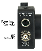
The power input and BNC connectors are located at the top of the PDA and PDF detector housings.
Click to Enlarge
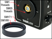
The housings of Thorlabs' detectors feature internal SM05 and external SM1 threads. An SM1T1 SM1 Adapter with internal threads is included with each amplified photodetector, and an SM1RR Retaining Ring is included with the PDA015C2, PDF10C2, PDA20C2, PDA10D2, PDA05CF2, PDA10CS2, and PDA20CS2.
Housing Features of the Amplified InGaAs Photodetectors
Please refer to the table below for detailed drawings of each detector.
PDA and PDF Detectors
Thorlabs' Amplified Photodiode series feature a slim design with many common elements. Each housing features internal SM05 (0.535"-40) threading and external SM1 (1.035"-40) threading, and includes a detachable SM1T1 internally SM1-threaded adapter, as shown to the right. The SM1T1 can hold up to 0.1" (2.8 mm) thick optics. An SM1RR retaining ring is included with every detector. Each detector can be mounted using a Ø1/2" Post, as shown in the images below. Detectors with universal taps (refer to the table below) have a new housing design. Except for the PDF10C2 and PDA20C2, these detectors feature an active area flush with the front of the housing, simplifying alignments within optomechanical systems. As a convenience, the back panels of these detectors are engraved with the responsivity curve of the photodiodes.
Lens Tube Compatibility
These detectors can be integrated into various optomechanical systems using the internal SM05 and external SM1 threads. A lens tube can be directly attached to the SM1 threads, making the detectors compatible with lens tube systems. The SM1T1 adapter can be used to mount Ø1" (Ø25.4 mm) optical components, such as optical filters and lenses.
Cage System Compatibility
The detectors are also cage system compatible, as shown in the two images below right. A CP33(/M) cage plate can be attached directly to the SM1 threads. This attachment method does not require an adapter piece and allows the diode to be as close as possible to the cage plate, which can be important in setups where the light is divergent. Another method for integrating a detector into a cage system is using the included SM1T1 with an SM1T2 adapter. This allows more freedom in choosing the orientation of the detector. Additionally, these detectors can be used with SM1-threaded fiber adapters (sold below).
Post Mounting
Threaded holes on the housings of the detectors allow the units to be mounted in a horizontal or vertical orientation using a Ø1/2" Post. This gives the user the option to route the power and BNC cables from above or alongside the beam path, as shown below left. We offer detectors that have metric and imperial versions, as well as detectors that have universal mounting holes that accept 8-32 and M4 threads. Please see the table below for the specific mounting taps of each detector.
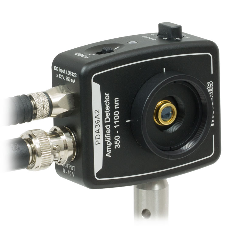
Click to Enlarge
PDA Photodetector Mounted Horizontally
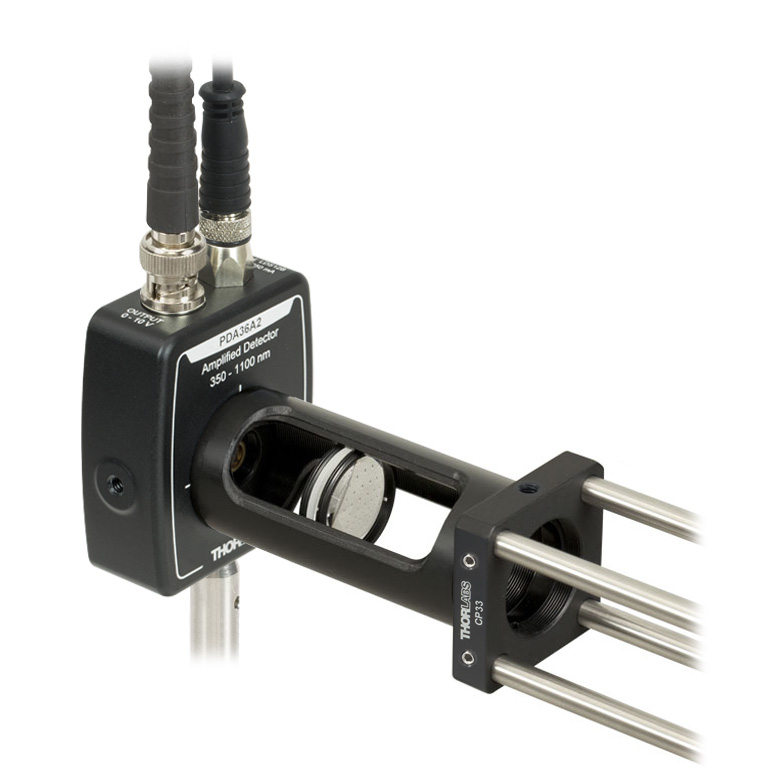
Click to Enlarge
PDA Photodetector Connected to an SM1 Lens Tube in a 30 mm Cage System
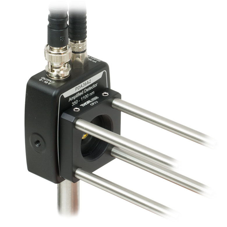
Click to Enlarge
PDA Photodetector Integrated into a 30 mm Cage System Using the External SM1 Threads
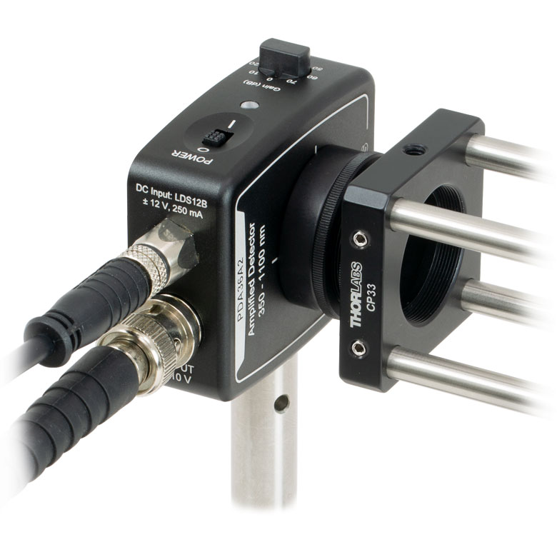
Click to Enlarge
PDA Photodetector Integrated into a 30 mm Cage System Using the SM1T1 (included) and SM1T2 Adapter
FPD Detectors
The housing of each of Menlo Systems' FPD detectors feature one M4 tapped hole on the bottom for post mounting. The power supply connector and output SMA connector are located on the side of the housing.
PDA and PDF Series Detectors
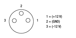
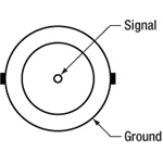
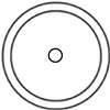
BNC Female 0 - 10 V Output (Photodetector)
0 - 10 V Output
Male (Power Cables)
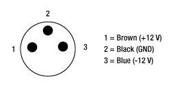
Female Power IN (Photodetector)
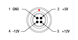
FPD Series Detectors
Signal Out- SMA Female (Photodetector)
For connection to a suitable monitoring device, e.g. oscilloscope or RF-spectrum-analyzer, with 50 Ω impedance.
Female (Power Cables)
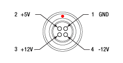
Male Power IN (Photodetector)
Photodiode Tutorial
Theory of Operation
A junction photodiode is an intrinsic device that behaves similarly to an ordinary signal diode, but it generates a photocurrent when light is absorbed in the depleted region of the junction semiconductor. A photodiode is a fast, highly linear device that exhibits high quantum efficiency and may be used in a variety of different applications.
It is necessary to be able to correctly determine the level of the output current to expect and the responsivity based upon the incident light. Depicted in Figure 1 is a junction photodiode model with basic discrete components to help visualize the main characteristics and gain a better understanding of the operation of Thorlabs' photodiodes.

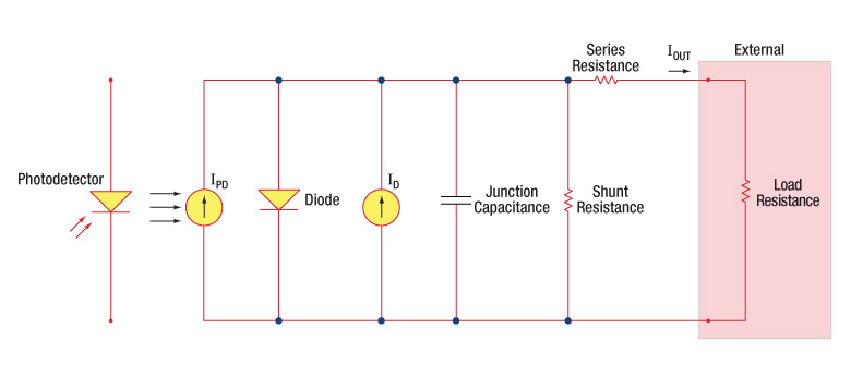
Figure 1: Photodiode Model
Photodiode Terminology
Responsivity
The responsivity of a photodiode can be defined as a ratio of generated photocurrent (IPD) to the incident light power (P) at a given wavelength:

Modes of Operation (Photoconductive vs. Photovoltaic)
A photodiode can be operated in one of two modes: photoconductive (reverse bias) or photovoltaic (zero-bias). Mode selection depends upon the application's speed requirements and the amount of tolerable dark current (leakage current).
Photoconductive
In photoconductive mode, an external reverse bias is applied, which is the basis for our DET series detectors. The current measured through the circuit indicates illumination of the device; the measured output current is linearly proportional to the input optical power. Applying a reverse bias increases the width of the depletion junction producing an increased responsivity with a decrease in junction capacitance and produces a very linear response. Operating under these conditions does tend to produce a larger dark current, but this can be limited based upon the photodiode material. (Note: Our DET detectors are reverse biased and cannot be operated under a forward bias.)
Photovoltaic
In photovoltaic mode the photodiode is zero biased. The flow of current out of the device is restricted and a voltage builds up. This mode of operation exploits the photovoltaic effect, which is the basis for solar cells. The amount of dark current is kept at a minimum when operating in photovoltaic mode.
Dark Current
Dark current is leakage current that flows when a bias voltage is applied to a photodiode. When operating in a photoconductive mode, there tends to be a higher dark current that varies directly with temperature. Dark current approximately doubles for every 10 °C increase in temperature, and shunt resistance tends to double for every 6 °C rise. Of course, applying a higher bias will decrease the junction capacitance but will increase the amount of dark current present.
The dark current present is also affected by the photodiode material and the size of the active area. Silicon devices generally produce low dark current compared to germanium devices which have high dark currents. The table below lists several photodiode materials and their relative dark currents, speeds, sensitivity, and costs.
| Material | Dark Current | Speed | Spectral Range | Cost |
|---|---|---|---|---|
| Silicon (Si) | Low | High Speed | Visible to NIR | Low |
| Germanium (Ge) | High | Low Speed | NIR | Low |
| Gallium Phosphide (GaP) | Low | High Speed | UV to Visible | Moderate |
| Indium Gallium Arsenide (InGaAs) | Low | High Speed | NIR | Moderate |
| Indium Arsenide Antimonide (InAsSb) | High | Low Speed | NIR to MIR | High |
| Extended Range Indium Gallium Arsenide (InGaAs) | High | High Speed | NIR | High |
| Mercury Cadmium Telluride (MCT, HgCdTe) | High | Low Speed | NIR to MIR | High |
Junction Capacitance
Junction capacitance (Cj) is an important property of a photodiode as this can have a profound impact on the photodiode's bandwidth and response. It should be noted that larger diode areas encompass a greater junction volume with increased charge capacity. In a reverse bias application, the depletion width of the junction is increased, thus effectively reducing the junction capacitance and increasing the response speed.
Bandwidth and Response
A load resistor will react with the photodetector junction capacitance to limit the bandwidth. For best frequency response, a 50 Ω terminator should be used in conjunction with a 50 Ω coaxial cable. The bandwidth (fBW) and the rise time response (tr) can be approximated using the junction capacitance (Cj) and the load resistance (RLOAD):

Noise Equivalent Power
The noise equivalent power (NEP) is the input signal power that results in a signal-to-noise ratio (SNR) of 1 in a 1 Hz output bandwidth. This is useful, as the NEP determines the ability of the detector to detect low level light. In general, the NEP increases with the active area of the detector and is given by the following equation:

Here, S/N is the Signal to Noise Ratio, Δf is the Noise Bandwidth, and Incident Energy has units of W/cm2. For more information on NEP, please see Thorlabs' Noise Equivalent Power White Paper.
Terminating Resistance
A load resistance is used to convert the generated photocurrent into a voltage (VOUT) for viewing on an oscilloscope:

Depending on the type of the photodiode, load resistance can affect the response speed. For maximum bandwidth, we recommend using a 50 Ω coaxial cable with a 50 Ω terminating resistor at the opposite end of the cable. This will minimize ringing by matching the cable with its characteristic impedance. If bandwidth is not important, you may increase the amount of voltage for a given light level by increasing RLOAD. In an unmatched termination, the length of the coaxial cable can have a profound impact on the response, so it is recommended to keep the cable as short as possible.
Shunt Resistance
Shunt resistance represents the resistance of the zero-biased photodiode junction. An ideal photodiode will have an infinite shunt resistance, but actual values may range from the order of ten Ω to thousands of MΩ and is dependent on the photodiode material. For example, and InGaAs detector has a shunt resistance on the order of 10 MΩ while a Ge detector is in the kΩ range. This can significantly impact the noise current on the photodiode. For most applications, however, the high resistance produces little effect and can be ignored.
Series Resistance
Series resistance is the resistance of the semiconductor material, and this low resistance can generally be ignored. The series resistance arises from the contacts and the wire bonds of the photodiode and is used to mainly determine the linearity of the photodiode under zero bias conditions.
Common Operating Circuits
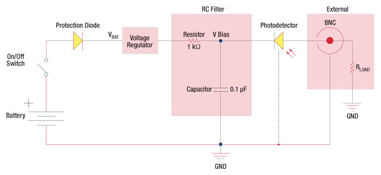
Figure 2: Reverse-Biased Circuit (DET Series Detectors)
The DET series detectors are modeled with the circuit depicted above. The detector is reverse biased to produce a linear response to the applied input light. The amount of photocurrent generated is based upon the incident light and wavelength and can be viewed on an oscilloscope by attaching a load resistance on the output. The function of the RC filter is to filter any high-frequency noise from the input supply that may contribute to a noisy output.
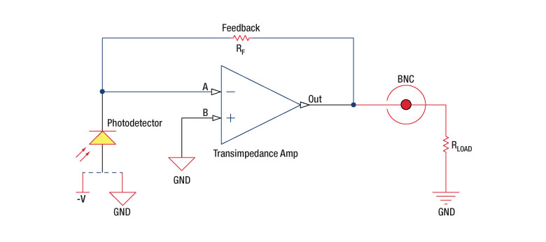
Figure 3: Amplified Detector Circuit
One can also use a photodetector with an amplifier for the purpose of achieving high gain. The user can choose whether to operate in Photovoltaic of Photoconductive modes. There are a few benefits of choosing this active circuit:
- Photovoltaic mode: The circuit is held at zero volts across the photodiode, since point A is held at the same potential as point B by the operational amplifier. This eliminates the possibility of dark current.
- Photoconductive mode: The photodiode is reversed biased, thus improving the bandwidth while lowering the junction capacitance. The gain of the detector is dependent on the feedback element (Rf). The bandwidth of the detector can be calculated using the following:
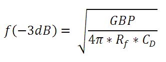
where GBP is the amplifier gain bandwidth product and CD is the sum of the junction capacitance and amplifier capacitance.
Effects of Chopping Frequency
The photoconductor signal will remain constant up to the time constant response limit. Many detectors, including PbS, PbSe, HgCdTe (MCT), and InAsSb, have a typical 1/f noise spectrum (i.e., the noise decreases as chopping frequency increases), which has a profound impact on the time constant at lower frequencies.
The detector will exhibit lower responsivity at lower chopping frequencies. Frequency response and detectivity are maximized for
![]()
The following table lists Thorlab's selection of previous and current generation PDA, PDF, and DET detectors.
| Previous Generation Cross Reference of PDA and DET Detectors | |||||
|---|---|---|---|---|---|
| Wavelength | Material | Biased Detector |
Amplified Detector |
||
| Current Generation | Previous Generation | Current Generation | Previous Generation | ||
| 200 - 1100 nm | Si | DET10A2 | DET10A(/M) | PDA10A2 | PDA10A(-EC) |
| 320 - 1000 nm | Si | - | - | PDA8A2 | PDA8A |
| 400 - 1000 nm | Si | - | - | PDA015A2 | PDA015A(/M) |
| 320 - 1100 nm | Si | DET100A2 | DET100A(/M)a | PDA100A2 | PDA100A(-EC)b |
| Si | - | - | PDF10A2 | PDF10A(/M) | |
| 350 - 1100 nm | Si | DET36A2 | DET36A(/M) | PDA36A2 | PDA36A(-EC) |
| 500 - 1700 nm | InGaAs | DET10N2 | DET10N(/M) | - | - |
| 800 - 1700 nm | InGaAs | DET20C2 | DET20C(/M) | PDA20CS2 | PDA20CS(-EC) |
| - | - | PDA05CF2 | PDA10CF(-EC) | ||
| - | - | PDA015C2 | PDA015C(/M) | ||
| - | - | PDF10C2 | PDF10C(/M) | ||
| - | - | PDA20C2 | PDA20C(/M) | ||
| 800 - 1800 nm | Ge | DET30B2 | DET30B(/M) | PDA30B2 | PDA30B(-EC) |
| DET50B2 | DET50B(/M) | PDA50B2 | PDA50B(-EC) | ||
| 900 - 1700 nm | InGaAs | DET10C2 | DET10C(/M) | PDA10CS2 | PDA10CS(-EC) |
| 900 - 2600 nm | InGaAs | DET05D2 | DET05D(/M)c | PDA10D2 | PDA10D(-EC)c |
| DET10D2 | DET10D(/M)c | - | - | ||
| Posted Comments: | |
Stijn Mast
(posted 2024-02-02 16:15:01.733) Dear,
What is the maximum optical irradiance (e.g. in W/cm^2) that this detector can safely handle without damage?
Thanks,
Stijn Mast ksosnowski
(posted 2024-02-02 12:55:33.0) Hello Stijn, thanks for reaching out to Thorlabs. The max power level for the PDA20CS2 detector will depend on the wavelength used as well as the gain. Any inputs that lead to the maximum output voltage should be avoided as this saturates the amplifier and can damage the detector. On the PDA series, the amplifier will saturate before the photodiode itself, and this is going to occur well before surface damage is induced unless a very tiny beam is used. I recommend trying to fill ~80% of the sensor area, which helps eliminate any potential high power density on the sensor, and also prevents potential overfilling which causes loss and bandwidth issues. With the lowest gain setting of 1.51 kV/A and peak response around 1 A/W, you would hit saturate the output around 6mW, or with less power at higher gain settings. I have reached out directly to discuss your application further. Dodd Gray
(posted 2023-09-08 10:38:39.38) Are some/all of your amplified photodetectors compatible with a +/-15V power supply? I assume these are the rail voltages for amplifier ICs in the TIA circuits, but I could not find max DC power supply voltage ratings in the datasheets. If possible I would like to power several amplified InGaAs detectors and other control circuits with the same +/-15V linear power supply rails. Thanks! ksosnowski
(posted 2023-09-13 11:11:25.0) Hello Dodd, thanks for reaching out to Thorlabs. We do not typically recommend using a +/-15V supply as this causes extra heating in the amplifier and in cases like with 50 Ohm termination this can damage the amplifier with the amount of current passed. We further recommend to operate with the designed 12V supply voltage as modifications to the detector system could complicate future operation since our standard detector systems are typically rated for 50 Ohm loading and a supply voltage modification may not be apparent to other users of the system. I have reached out directly to discuss your application in further detail. Gearoid Whelan
(posted 2023-08-16 13:41:58.203) Hi,
I want to enquire if the PDA10D2 can be calibrated? If so can you do the calibration and provide a calibration cert?
Best regards,
Gearoid ksosnowski
(posted 2023-08-16 11:36:17.0) Hello Gearoid, thanks for reaching out to Thorlabs. Unfortunately we do not offer calibrations on the PDAx series of amplified photodetectors. For applications requiring <100kHz bandwidth our Calibrated Photodiode Power Sensors like S122C may be useful. We do offer one bare Calibrated InGaAs Photodiode as our FGA21-CAL, however we are only able to perform the calibration at zero-bias point, so while the exact responsivity should not change with bias we cannot particularly guarantee the calibration data under different biases as the bias does effect the noise floor and saturation conditions. I have reached out directly to discuss your application further. Alex Pa
(posted 2023-02-05 00:55:24.973) Hello,
The signal I want to measure with detectors is modulated CW laser at 1550 nm (fiber coupled). The laser is modulated into ~8ns pulses while pulse peak power is in the range of 1mW to 1uW. Time between pulses can be anything between 10 ns and few ms,
so I am looking for DC coupled detectors only. I am choosing from PDA015C and FPD610-FC-NIR. According to my understanding the first one will be saturated at 0.2mW and the second one will be saturated at 2uW. In general I can attenuate my optical signal, but I need to get the maximum dynamic range considering that my scope can measure in the range of 5V to 5mV. It seems like the first option (PDA015C) is preferable since it can produce output of 5V. Does it make sense? Are there other options?
Thank you ksosnowski
(posted 2023-02-16 10:11:52.0) Hello Alex, thanks for reaching out to Thorlabs. The dynamic range for a detector has an upper limit due to saturation and lower limit due to the noise floor of the device. Spectral responsivity, gain, NEP, and the actual measurement setup can effect both of these limits. For questions like this we recommend emailing techsupport@thorlabs.com directly. I have reached out to discuss your application further. user
(posted 2020-10-19 18:32:01.433) Hello,
In manual, we see both NEP and Noise(RMS) for each gain setting. If we want to know the total noise, we simply calculate from NEP, bandwidth and gain. The calculated one is different from Noise(rms).
So what is Noise(rms) in this manual? and how to calculate the total noise of the measured signal?
Thank you,
Steve asundararaj
(posted 2020-10-30 09:09:23.0) Thank you for contacting Thorlabs. The NEP and the RMS noises were characterized using different equipment. The NEP was measured using the spectrum analyzer which gives the curve vs bandwidth. The RMS noises however were measured using a 1.5GHz oscilloscope. As there is no bandwidth cutoff, all of the signals/noises up to the scope’s bandwidth would be measured/recorded. Also the scope’s own noise baseline would be there too. Thus, it is normal that the RMS noise is higher than the calculated number. The reason we provides an RMS is that we wanted to give the user a more intuitive number of what the noise could be when measuring with a scope. Nicolas Védrenne
(posted 2020-09-05 22:41:01.153) Hello. I would be interested to know the mechanical position of the photodetector plane with respect to the mechanical housing (for instance). I would like to know if the focus position of the camera lens MVL100M23 + SM05A1 adapter would fit with a PDA20CS2 without any mechanical adjustment to ensure a correct focusing of the light coming from infinity or if I must add an adaptation ring to secure the focusing. asundararaj
(posted 2020-10-26 10:07:24.0) Thank you for contacting Thorlabs. The photodetector surface is flush with the front of the housing as indicated in the AutoCAD drawing. The MVL100M23 is a standard C-mount machine vision lens which has a flange back distance to the sensor area of 17.526 mm. When used with standard C-mount cameras, this will require no mechanical adjustment. With the PDA20CS2, this will require some adjustment. For most applications, using a simple plano-convex lens might be sufficient to collect light from infinity to be detected. Hoang Nguyen
(posted 2019-04-19 14:39:07.52) What is the saturation power for PDA20CS2, at each gain level? What is the maximum power the PDA can tolerate? Thanks. YLohia
(posted 2019-04-19 04:45:38.0) The saturation power can be calculated from the V_Out equation in the PDA manuals by setting V_Out equal to the maximum voltage output for the detector (for a High-Z impedance), and setting the scale factor equal to 1 (the scale factor for High-Z impedance). Please note that the saturation power will be independent of the load impedance: V_Max = Responsivity (λ) ∗ Transimpedance Gain ∗ [Max Input Power] (W) The optical saturation power is independent of load impedance, since V_max and the scale factor from the full V_Out equation both change in the same proportion as the load changes.
A conservative value for the damage threshold would be ~100 W/cm^2 average power density (but it can often be closer to 100 kW/cm^2) or about 100 mW total average power. We don't typically spec a damage threshold for photodiodes for two main reasons: the output voltage will saturate several orders of magnitude before damaging the surface, and only CW (average power) damage is a concern for most situations. For pulsed sources, the active area is less prone to pulsed damage mechanisms (e.g. dielectric breakdown/avalanche ionization). The primary damage mechanism is thermal burning at the PN junction. Both CW and pulsed damage will strongly depend on usage conditions so you should use these numbers as guideline only and not as an official spec. Also note that the max current output is specified to be 100mA. So depending on the gain setting and wavelength, the current should always be less than 100mA. This information applies to all PDAs on this page (please double check the max current rating on the manual for future releases as this spec may change). kallmyer
(posted 2019-01-24 15:05:13.633) I am planning to use the PDF10C and PDA-C-72 in a portable device and need it to run on battery power. My current plan is to use two 12V batteries in series to achieve the +12, 0, and -12 V. I also plan to add a simple RC circuit to achieve a soft start and a slow blow fuse for overcurrent protection. Do you have any recommendations on running these photodetectors with battery power? nreusch
(posted 2019-04-16 03:53:18.0) This is a response from Nicola at Thorlabs. Thank you for your inquiry! While the PDF10C is not designed to be operated by battery, we still assume that the setup you suggested should work. user
(posted 2019-01-10 09:25:02.723) What is the maximum optical input power of PDA10D2 for linear operation? YLohia
(posted 2019-01-11 04:44:01.0) The saturation power can be calculated from the V_Out equation in the PDA manuals by setting V_Out equal to the maximum voltage output for the detector (for a High-Z impedance), and setting the scale factor equal to 1 (the scale factor for High-Z impedance). Please note that the saturation power will be independent of the load impedance:
V_Max = Responsivity (λ) ∗ Transimpedance Gain ∗ [Max Input Power] (W)
The optical saturation power is independent of load impedance, since V_max and the scale factor from the full V_Out equation both change in the same proportion as the load changes. user
(posted 2018-07-01 21:53:00.79) I hope the maximum optical input power that can be fed to the photodetector, e.g. PDA015C/M is the same as the damage threshold YLohia
(posted 2018-07-03 10:05:05.0) Please see the comment on the saturation/damage threshold spec for the PDA015C/M below. user
(posted 2018-06-15 07:43:08.627) What is the damage threshold of PDA015C/M photodetectors as it's saturation power is 350 microwatt YLohia
(posted 2018-06-22 09:48:51.0) A conservative value would be ~100 W/cm^2 average power density (but it can often be closer to 100 kW/cm^2) or about 100 mW total average power. We don't typically spec a damage threshold for photodiodes for two main reasons: the output voltage will saturate several orders of magnitude before damaging the surface, and only CW (average power) damage is a concern for most situations. For pulsed sources, the active area is less prone to pulsed damage mechanisms (e.g. dielectric breakdown/avalanche ionization). The primary damage mechanism is thermal burning at the PN junction. Both CW and pulsed damage will strongly depend on usage conditions so you should use these numbers as guideline only and not as an official spec. michael.vandegraaaff
(posted 2018-03-13 11:55:30.23) We have some older PDA10CS detectors in our lab. On the detector it is labeled 700-1800 nm. However the PDA10CS part currently available for purchase is only spec'd from 900-1700 nm.
We have been using these for measuring 767nm light so this is relevant for us; do you have data down to 700nm or data for the older product. Can you explain the reason for the discrepancy?-Thank you YLohia
(posted 2018-03-16 09:27:04.0) Hello Michael, thank you for contacting Thorlabs. We tightened the specs of our PDA and DET detector lines in June 2015. The actual photodiode, as well as the circuitry of the detector, is still the same. Having the lower range as 900nm in the latest revision of the spec sheet does not necessarily mean that the unit will not be able to detect 767nm light. You may just have a low output signal from the unit, depending on the input optical power at this wavelength. I have reached out to you directly to discuss this further. sergio.vilches
(posted 2017-08-08 15:39:48.433) NEP value of PDA10D is shown as 0.35 pW/sqrtHz in one of the tables.
Probably it is 35 pW/sqrtHz ? tfrisch
(posted 2017-08-16 04:48:23.0) Hello, thank you for bringing this to our attention. The NEP is 3.5x10^(-11)W/sqrt(Hz) as listed in the manual. This corresponds to 35pW/sqrt(Hz). I will reach out to you directly to clarify this as well. user
(posted 2017-04-04 05:50:02.717) What's the damage threshold for PDA10CS? Is it related to maximum current in the electric unit or determined by the maximum optical power density on the active area? tfrisch
(posted 2017-04-26 01:49:55.0) Hello, thank you for contacting Thorlabs. We do not list a damage threshold for these detectors as they will saturate before they are damaged. They are only intended for use in the region with linear response. Whether it is the gain electronics or photodiode which saturates first will depend on the gain setting. Please reach out to TechSupport@Thorlabs.com to discuss further with one of our Applications Engineers. melanie
(posted 2017-01-26 07:37:36.047) Please can you tell me the max operating temperature of this photodiode, and also the 10CS,
thank you tcampbell
(posted 2017-01-26 09:06:13.0) Response from Tim at Thorlabs: thank you for your question. The maximum operating temperature of the PDA20CS(-EC) is 70 °C, and the maximum operating temperature of the PDA10CS(-EC) is 40 °C. These values are given in chapter 6 of the manuals. We will add this information to the web to make it easier to find. grafen
(posted 2016-05-04 14:01:19.97) Hello,
we use this photodiode for two-photon absorption. Can you tell me of which material the front window is? besembeson
(posted 2016-05-05 10:21:11.0) Response from Bweh at Thorlabs USA: The window material for the PDA10D is borosilicate. bernhard.reitinger
(posted 2015-06-02 17:40:49.587) Dear ladies and gentleman.
I think the PDF10CF is really a great product and the price compared to the biased version is what it makes even more great.
Unfortunately in our application (interferometry) we would need an AC-coupled version.
Would it be possible to add such a version in your portfolio?
Best Regards
Bernhard Reitinger jlow
(posted 2015-06-05 09:39:33.0) Response from Jeremy at Thorlabs: Thank you very much for the feedback. We will look into offering the AC-coupled version or offer it as a special. We will contact you directly about this. Karthekab
(posted 2015-04-10 11:21:38.703) The Adapter doesn't show the green light and I guess the current is not passing through it.
Can you please help me with this issue jlow
(posted 2015-04-14 09:57:47.0) Response from Jeremy at Thorlabs: Please make sure the voltage selection switch is set to the correct setting. It could also be that the fuse is blown. I will contact you directly to troubleshoot more about this. user
(posted 2015-02-02 16:36:14.25) Are the bandwidths quoted single-sided or double-sided ?
Thank you jlow
(posted 2015-02-03 03:58:43.0) Response from Jeremy at Thorlabs: These are measured from DC so it should be single-sided. Paul.Wallace
(posted 2014-05-09 13:04:28.943) We are using multiple numbers of this product (40) in an AWG. A power supply to power multiple units would be a great help. Controling mains leads to 40 power supplys is horid jlow
(posted 2014-06-11 10:32:30.0) Response from Jeremy at Thorlabs: Thank you for contacting Thorlabs. We will look into the possibility of providing this custom power supply for you and contact you directly. marcelogodin
(posted 2012-09-06 09:45:57.0) Hello I recently bought a PDA36A with the intention of measuring current due to light radioluminescence. I connected a photodiode PDA36A to an electrometer and I measured a noise about 150 nA. Is this normal?
PDA36A noise is higher than DET36A? jlow
(posted 2012-08-09 10:28:00.0) Response from Jeremy at Thorlabs: Using the SolidWorks, the typical FOV for the different PDA is listed below.
PDA100A: 53.13°,
PDA36A: 70.19°,
PDA10A: 122.92°,
PDF10A: 127.81°,
PDF8A: 150.64°. ben.aernouts
(posted 2012-07-31 17:34:45.0) Dear,
Is it possible to provide me with the Field of View (FOV) of following Thorlabs Amplified Si detectors:
PDA10A
PDA8A
PDF10A
PDA36A
PDA100A
Many thanks and best regards,
Ben Aernouts
Department Biosystems, Division MeBioS
KULeuven tcohen
(posted 2012-05-15 09:49:00.0) Response from Tim at Thorlabs: Thank you for your feedback! Our superseded products can be found by utilizing the search bar where the original supporting documentation is left intact. I am not sure that the part number you specified was our original part number. I will send you an overview of the old web presentation in order to determine the part number and provide supporting documentation for the correct product. ryanbrock2011
(posted 2012-05-11 18:54:17.0) Is the "New vs. Old" page mentioned in the older comments no longer on this site? I am looking for information on an old PDA-50 Si Amplified Photodetector bdada
(posted 2012-01-25 15:15:00.0) Response from Buki at Thorlabs:
We specify at least +/- 12V, 125mA. However this is very conservative, especially if the PDA is driving a high impedance load. Most of the current usage is for driving the output. A 50Ohm load with the maximum output voltage (5V) will require a current of 100mA (5V/50Ohms). The amplifier itself uses approximately +/- 25mA from +/-12V supplies. The +12V supply needs to be able to supply an additional 100mA if it is driving a 50Ohm load.
Please contact TechSupport@thorlabs.com if you have any questions. andrew.beeby
(posted 2012-01-25 10:37:37.0) Could you advise what current the device draws at +/- 12V if we want to use our own power supply? Thorlabs
(posted 2010-11-08 10:01:42.0) Response from Javier at Thorlabs to Nathan: Thank you for your feedback. The PDA10CF and PDA10CS detectors have not been superseded. We are currently working with our web team to reactivate the shopping cart option so that you can order them through the web. You can also contact our sales department st sales@thorlabs.com or by phone at (973) 579 7227 to place an order. nathan.flowers-jacobs
(posted 2010-11-08 08:50:43.0) Have you discontinued the PDA10CF & PDA10CS detectors? They are still included in the overview and specs tabs, but I cant find more detailed information or an option for purchasing? Or is there a replacement part (particularly for the variable gain version, but also for the fixed gain/high bandwidth version)? Thanks. Thorlabs
(posted 2010-11-04 18:21:38.0) Response from Javier at Thorlabs to imag: all of our photodiodes have a protective resin or coating. In order to remove dust, we would suggest gently blowing pressurized air onto the surface of the detector, from a ~6" distance. If further cleaning is needed, you can use ethyl alcohol an wipe off the dirt carefully. It is not recommended to use organic solvents, as they can degrade the quality of any resin coating or filters. imag
(posted 2010-11-03 17:42:40.0) I have a bunch of Thorlabs Si-photodiodes, biased and amplified. What is the procedure for the sensing area cleaning in the case if gets dirty or dusty ? Unlike conventional photodiodes, these detectors are not in some protective case with transparent window. Do they really have any protective layer on the Si ? jens
(posted 2009-09-06 17:47:28.0) A reply from Jens at Thorlabs: as for the maximum power we do not recommend to use more than 100mW over the detector area. You will find higher values in some publications, depending on wavelenght and exposure time and this value is more on the safe side. As to the inhomogenity the laser point located at different spots on the detector surface does indeed not produce the same conversion because of boundary conditions. These boundary conditions vary from diode to diode. To get a true estimate we can map out the area of the photo diode. I will contact you with additional data regarding the measurement. If possible the 2/3 rule (i.e. filling 2/3 of the detector aperture) should be followed. flo6137
(posted 2009-08-31 12:38:28.0) Hi, I am currently using a PDA100A but it seems that the sensitivity to the impinging laser light is not the same on all area of the photon detector. We have almost 10% of difference between different area.
It might be possible that our PDA100A had been damaged by being exposed to a high power laser beam.
But before buying a new one, could you please provide me some information about the accuracy of this photon detector (I mean the difference of sensitivity between the different cells of the detector) and about the maximum power that we can use without damaging the detector. klee
(posted 2009-08-03 17:36:13.0) A response from Ken at Thorlabs to asd: All the US and EC versions had different power supplies originally and the EC (220-240VAC) power supplies were more expensive. We did not change to the current new switchable power supply until about a year ago. We will be updating the prices shortly. asd
(posted 2009-08-02 18:11:34.0) How come the the PDA3A-EC is so much more expensive than the PDA36A?
The other detectors dont show this skew in price and the PSUs are identical.
Looks like a consumer annoying cock up. klee
(posted 2009-07-09 10:00:13.0) A response from Ken at Thorlabs to perry.gray: We do carry SM1 to C-mount adapters. SM1A10 has external SM1 Threads and internal C-Mount Threads while SM1A9 has internal SM1 Threads and external C-Mount Threads. perry.gray
(posted 2009-07-08 21:35:37.0) You guys need a C-mount adapter for your PDA series diodes so I can mount my existing c-mount tv camera lenses on my PDA diode housings user
(posted 2009-06-09 13:16:54.0) A response from Adam at Thorlabs to Letizia: Hi, We do not have data on the thermal drifts for these units. If you provide me with the temperature ranges you may be using the PDA25k at , I can check with our electronics engineers and see if we can provide more inforamtion. My email address is apalmentieri@thorlabs.com. user
(posted 2009-06-09 11:42:19.0) Response from Adam at Thorlabs, Inc. Hi, I have spoken with our electronics engineers and there should be no need to distance the power supply from the photodiode. I am also checking with our engineers to see if we can provide any data about the shot noise. As soon as I have more information, I will send you an email. If you have further questions or concerns, feel free to contact me, apalmentieri@thorlabs.com. slamkadmi
(posted 2009-06-09 11:28:37.0) Hello,
I need to know if there is any requirement concerning the distance from the power supply to the photodiode. I have just seen a comment saying that "the power supply needs to be located about 5 meters away". Could you tell me more about that? I also need some data concerning the shot noise. Can the phase of the signal be deteriorated by the photodiode? In fact, we need to extract the phase from the output signal and we need a very high precision on the signal phase. If you do have any data, please let me know.
Thanks in advance.
Best regards letizia.demaria
(posted 2009-04-15 03:47:47.0) could you please specify the temperature coefficient (thermal drift) for PDA25k?
thank you
ldm Laurie
(posted 2009-01-22 11:00:47.0) Response from Laurie at Thorlabs to lee: Thank you for your interest in Thorlabs Products. A member of our technical support staff will be contacting you directly. We need a bit of clarification concerning your inquiry prior to discussing possible solutions. lee
(posted 2009-01-20 04:13:57.0) I plan to use PDA10A in an equipment, but the power supply needs to be located about 5 meters away. Ill be using a linear +/-12V power supply on DIN rail. I prefer to make the power supply cable in house, and so Id appreciate it if (1) Thorlabs sells the cable-side power connector (not the whole cable like PDA-C-72), or (2) gives relevant information such as connector manufacturer and part number. Laurie
(posted 2008-12-10 13:37:22.0) Response from Laurie at Thorlabs to jwerly: Thank you for your feedback concerning our PDA photodetectors. The transimpedance photocurrent amplifier assembly is built directly into the circuitry of the PDA detector, and thus, it is not possible to control the amplification externally or through some other method. Detectors like the PDA36A have switchable gain, but again, there is no way to adjust the amplification. jwerly
(posted 2008-12-09 09:11:15.0) Hello, I have a question about your PDA series. I would know how can we control the amplification. I mean, is it an automiticaly, a manualy or even a manualy by an electronic interface ?
Regards, Julien Werly. sal
(posted 2008-03-06 09:55:47.0) Response from Sal at Thorlabs to jschumacher, ghegenbart, and acable:
Numerous changes have been made to this page to address the postings below. The PDA8GS is a high-speed, fiber coupled detector that is now included with the other detectors in that family. The FPD310 high speed PIN photodiode module is accessible directly from its own window in the Biased and Amplified Detector Visual Navigation pane. Regarding this page, the pin description for the PDA Power Connector is in a diagram immediately next to the price and description of this component. All detectors are now grouped by material type (InGaAs and Ge are separated). The New vs. Old tab includes explicit references between current and superseded devices and the superseded devices are hot links that will lead to their documentation. This arrangement insures easy access to the old part information. The Overview tab has been completely reorganized to present the modules grouped both by high level feature (Switchable Gain, Wideband, etc.), application, and detector type (Si, InGaAs, etc.). The Specs tab also has been grouped by detector type. Gain figures are easy to read and units are expressed in both V/A and ohms since both units are generally used. Finally, under the Graphs tab a complete set of spectral responsivity data is included for each model number. We continually strive to assist our customers in finding the product that is best suited to their application. Thanks for your continued business. technicalmarketing
(posted 2007-12-27 16:44:57.0) In response to ghegenbarts comments, we have split the InGaAs and Ge subgroups as was done with the DETs page. We have also updated the product descriptions to be more uniform. Please note that acables comments are still being addressed by the technical marketing group. We thank you for your input, and hope that you find these changes to be helpful. acable
(posted 2007-12-12 05:55:15.0) Your "Specs" tab would be much easier to read if it was separated by detector type, when using the chart i am forced to piece together what Si detectors are available, it is great to have a large selection of products but as you expand the selection please realize that more thought should go into how you organize the presentation. I would also suggest a selection table right on the Overview tab, all the text is great for the first time visitor, added the table would just complete the overview picture faster for your more experienced customers.
Another point that is confusing for me as a repeat customer is the non-uniformity of the product descriptions in the price boxes. Since i know the detector family fairly well and just need to pick out the right model it would be great to have all the relevant information right in your price table, there seems to be room. For me the order of importance is:
What it Is: Handled with your Price Box Header
Material: (which you handle well by separating the boxes by material)
Bandwdith: (highest if switchable gain but provide foot note)
Gain: (number if fixed and range if variable)
Wavelength Range: (given by material in most cases)
Ex: PDA10A, 150MHz BW, 5KOhm Gain, 200-1100nm Detector
Also, my sense is that the transimpedence gain in units of Ohms is the standard way to specifiy an amplified detector, why the V/A, silly little thing but it caused me to have to pause. acable
(posted 2007-12-12 05:27:23.0) I came to this page specifically to cross reference an old PDA part number to a new one and was disapointed to find that this information was not provided on the "New vs Old Design" tab. Can you add a simple chart and then ensure the internal search feature can "see" the old part numbers. Does your search feature even have the ability to send a visitor to a specific tab. ghegenbart
(posted 2007-11-26 08:14:26.0) I suggest not to combine InGaAs and Ge in one product group but have them listed separately like it is done for the DETs. jschumacher
(posted 2007-10-18 12:58:43.0) please add pin description for PDA power connector |
The following table lists Thorlabs' selection of photodiodes, photoconductive, and pyroelectric detectors. Item numbers in the same row contain the same detector element.

| Item #a | Housing Featuresb | Wavelength Range |
Bandwidth Range | Rise Time | Gain | NEP | Typical Performance Graphs | Active Areac |
Operating Temperature Range | Power Supply Included | |
|---|---|---|---|---|---|---|---|---|---|---|---|
| Hi-Z Load |
50 Ω Load | ||||||||||
| PDA015C2 |  |
800 - 1700 nm | DC - 380 MHz | 1.0 ns | 50 kV/A | 25 kV/A | 20 pW/Hz1/2 | 0.018 mm2 (Ø150 µm) |
10 to 40 °C | Yes | |
| PDA05CF2 | 800 - 1700 nm | DC - 150 MHz | 2.3 ns | 10 kV/A | 5 kV/A | 12.6 pW/Hz1/2 | 0.2 mm2 (Ø0.5 mm)d |
10 to 50 °C | Yes | ||
| PDF10C2 |  |
800 - 1700 nm | DC - 20 Hz | 19 mse | - | 0.2 mm2 (Ø0.5 mm) |
10 to 50 °C | Yes | |||
| PDA20C2 |  |
800 - 1700 nm | 70 ns | 500 kV/A | 175 kV/A | 22 pW/Hz1/2 | 3.14 mm2 (Ø2.0 mm) |
10 to 50 °C | Yes | ||
| PDA10D2 | 900 - 2600 nm | DC - 25 MHz | 15 ns | 10 kV/A | 5 kV/A | 10.1 pW/Hz1/2 | 0.8 mm2 (Ø1.0 mm)d |
10 to 50 °C | Yes | ||
| FPD510-FS-NIR | 950 - 1650 nm | DC - 250 MHz | 2 ns | - | 1.5 x 10⁵ Vpp/Wf 5 x 10⁴ Vpp/Wg |
3.2 pW/Hz1/2 | 0.07 mm2 (Ø0.3 mm) | 10 to 40 °C | Yes | ||
| FPD610-FS-NIR | 950 - 1650 nm | DC - 600 MHz | 1 ns | - | 2 x 10⁶ Vpp/Wf 5 x 10⁵ Vpp/Wg |
6.6 pW/Hz1/2 | 5 x 10⁻³ mm2 (Ø0.08 mm) |
10 to 40 °C | Yes | ||

| Item #a | Housing Featuresb | Wavelength Range |
Bandwidth Range | Gainc | NEP | Typical Performance Graphs | ActiveAread | Operating Temperature Range | Power Supply Included | |
|---|---|---|---|---|---|---|---|---|---|---|
| Hi-Z Load | 50 Ω Load | |||||||||
| PDA20CS2 | 800 - 1700 nm | DC - 11 MHz | 1.51 kV/A - 4.75 MV/A | 0.75 kVA - 2.38 MV/A | 1.95 - 61 pW/Hz1/2 |
3.14 mm2 (Ø2.0 mm)e |
10 to 40 °C | Yes | ||
| PDA10CS2 | 900 - 1700 nm | DC - 13 MHz | 1.51 kV/A - 4.75 MV/A | 0.75 kVA - 2.38 MV/A | 1.91 - 46 pW/Hz1/2 |
0.8 mm2 (Ø1.0 mm)e |
10 to 40 °C | Yes | ||
| FPD310-FS-NIR | 950 - 1650 nm | 1 MHz - 1.5 GHz | - | 2 x 10³ - 2 x 10⁴ Vpp/Wf | 14.1 pW/Hz1/2 | 5 x 10⁻³ mm2 (Ø0.08 mm) |
10 to 40 °C | Yes | ||

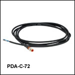
The PDA-C-72 power cord is offered for the PDA line of amplified photodetectors when using with a power supply other than the one included with the detector. The cord has tinned leads on one end and a PDA-compatible 3-pin connector on the other end. It can be used to power the PDA series of amplified photodetectors with any power supply that provides a DC voltage. The pin descriptions are shown to the right.

- Replacement Power Supply for the PDA and PDF Amplified Photodetectors Sold Above
- ±12 VDC Power Output
- Current Limit Enabling Short Circuit and Overload Protection
- On/Off Switch with LED Indicator
- Switchable AC Input Voltage (100, 120, or 230 VAC)
- 2 m (6.6') Cable with LUMBERG RSMV3 Male Connector
- UL and CE Compliant
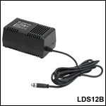
The LDS12B ±12 VDC Regulated Linear Power Supply is intended as a replacement for the supply that comes with our PDA and PDF line of amplified photodetectors sold on this page. The cord has three pins: one for ground, one for +12 V, and one for -12 V (see diagram to the right). A region-specific power cord is shipped with the unit based on your location. This power supply can also be used with the PDB series of balanced photodetectors, PMM series of photomultiplier modules,APD series of avalanche photodetectors, and the FSAC autocorrelator for femtosecond lasers.

- FC/PC (Narrow or Wide Key), FC/APC (Narrow Key or Wide Key), SMA, ST®*/PC, SC/PC, LC/PC, or Ø2.5 mm Ferrule Receptacles
- Light-Tight Construction When Used with SM1 Lens Tubes
- Compatible with Many of Our Photodiode Power Sensors
Note: The APC adapters have two dimples in the front surface that allow them to be tightened with the SPW909 or SPW801 spanner wrench. The dimples do not go all the way through the disk so that the adapter can be used in light-tight applications when paired with SM1 lens tubes.
FC/PC and FC/APC adapters are available with either narrow (2.0 mm) or wide (2.2 mm) key connectors; for more details on narrow versus wide key connectors, please see our Intro to Fiber tutorial.
The S120-25 ferrule adapter is designed without a locking connector mechanism and accepts fiber patch cables with Ø2.5 mm ferrules for quick measurements with photodetectors or power sensors.
*ST® is a registered trademark of Lucent Technologies, Inc.

- FC/PC (Narrow or Wide Key), FC/APC (Narrow or Wide Key), SMA, ST®*/PC, SC/PC, or LC/PC Receptacles
- Vacuum-Compatible Versions of FC/PC Wide-Key and SMA Receptacles Available
- Light-Tight When Used with SM1 Lens Tubes
- Compatible with Many of Our 30 mm Cage Plates and Photodetectors
Note: Each disk has four dimples, two in the front surface and two in the back surface, that allow it to be tightened from either side with the SPW909 or SPW801 spanner wrench. The dimples do not go all the way through the disk so that the adapters can be used in light-tight applications when paired with SM1 lens tubes. Once the adapter is at the desired position, use an SM1RR retaining ring to secure it in place.
FC/PC and FC/APC adapters are available with either narrow (2.0 mm) or wide (2.2 mm) key connectors; for more details on narrow versus wide key connectors, please see our Intro to Fiber tutorial.
*ST® is a registered trademark of Lucent Technologies, Inc.
 Products Home


 Zoom
Zoom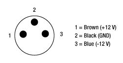


 InGaAs Free-Space Amplified Photodetectors