 Products Home
Polarizing Optical Fiber
- Polarizes Light Transmitted Through Fiber
- High Birefringence Produces High Polarization Extinction Ratios
- Design Wavelength: 830, 1064, or 1550 nm
- ~100 nm, Broad, Stable Polarizing Window
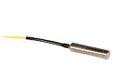
"Bow-Tie" Style PZ Fiber
Aligned
Polarization-Maintaining
Fiber
Coiled
Polarizing
Fiber
Single Mode
Fiber
Unpolarized
Light
Splicing Area
Polarized Light
Splicing Area
Polarized Light


Please Wait
Click to Enlarge
The polarizing window for these PZ fibers is defined as the wavelength range between the 20 dB attenuation of the fast axis and the 3 dB attenuation of the slow axis. For available graphs for each fiber type, please see the Graphs tab.
Click for Details
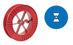
Bow-Tie-Style PM Fiber Cross Section

Features
- ~100 nm Polarizing Window
- ≥30 dB Extinction Ratio
- Design Wavelength: 830, 1064, or 1550 nm
- Applications:
- Fiber Optic Gyroscopes
- Coherent Communications
- Current Sensors
Thorlabs' Polarizing (PZ) fibers, also known as Zing™ fibers, are specialty optical fibers in which one and only one polarization state is allowed to propagate. Light with any other polarization direction will experience significant optical loss and thus is not propagated through the fiber. To create this effect, our PZ fiber utilizes bow-tie geometry to create an extreme birefringence. This birefringence ensures that only light with the proper polarization direction is guided through the fiber, whereas all other polarization directions experience high loss.
These PZ fibers offer a broad polarizing window (~100 nm), high extinction ratio (≥30 dB), and low attenuation. Polarization performance is specified using an Ø89 mm coil of roughly 5 m of fiber, which is about 16 turns; see the Specs tab for details. However, the polarizing window and extinction ratio can be tuned by coiling the PZ fiber (referred to as fiber deployment). Coiling the fiber to smaller diameters will narrow the polarization window and shift the window to lower wavelengths (see Graphs tab for more information). Note that performance cannot be guaranteed using coil diameters other than Ø89 mm. The polarizing window is defined between the 20 dB Fast Edge and 3 dB Slow Edge (see graph to the right).
PZ fibers are all-fiber devices with several advantages over in-line polarizers, such as lower insertion loss, higher extinction ratio, and no complex component assemblies or bulky packaging (see the PZ Tutorial tab). This cost-effective fiber delivers a high extinction ratio (ER), a bandwidth so wide that it will polarize at the design operating wavelength (830 nm for HB830Z, 1064 nm for HB1060Z, and 1550 nm for HB1550Z) even if the fiber is stressed, an ER and insertion loss that is stable with temperature, and long-term reliability in use. Our PZ fiber cleaves, handles, and splices just as any other silica fiber would and is compatible with standard PM fiber systems (both PANDA and bow-tie). This fiber also terminates just like any other PM fiber that requires low-stress epoxy and alignment of the key to the axis.
It is important to note that PZ fibers are not the same as Polarization-Maintaining (PM) fibers. While PM fibers maintain the linear polarization state when the polarization direction is aligned with the birefringence axis, they are also capable of propagating any polarization direction. Unlike PM fibers, PZ fibers suffer no polarization cross-talk, which makes them ideal for polarization-sensitive applications.
These fibers can be ordered as connectorized patch cables using our custom cables configurator. Please note that adding tubing may change fiber performance.
| Fiber Polarization Control Selection Guide | ||||||
|---|---|---|---|---|---|---|
| Polarization Controllers | Linear Polarizers | |||||
 |
 |
 |
 |
 |
 |
 |
| Motorized Fiber Polarization Controllers | Manual Paddle Fiber Polarization Controllers | In-Line Manual Fiber Polarization Controller | Free-Space FiberBench | Faraday Mirrors | In-Line Fiber Polarizers | Polarizing Fiber |
| Item #a | Operating Wavelengthb |
Cladding Diameter |
Coating Diameter |
MFDc | NAd | Cladding Indexe |
Core Indexe |
Cut-Off (Typ.)f |
Attenuation | Beat Length |
Extinction Ratiob |
20 dB Fast Edgeb,g |
3 dB Slow Edgeb,g |
|---|---|---|---|---|---|---|---|---|---|---|---|---|---|
| HB830Z | 830 nm | 80 ± 1 µm | 170 ± 10 µm | 4.1 - 7.7 µm @ 830 nm |
0.14 | 830 nm: 1.45954 |
830 nm: 1.45282 |
400 - 600 nm | ≤0.02 dB/m @ 830 nm |
≤1.04 mm @ 830 nm |
≥30 dB | ≤790 nm | ≥860 nm |
| HB1060Z | 1064 nm | 125 ± 1 µm | 245 ± 15 µm | 6 - 8 µm @ 1064 nm |
0.14 | 1064 nm: 1.45635 |
1064 nm: 1.44963 |
<1000 nm | ≤0.02 dB/m @ 1060 nm |
≤0.8 mm @ 633 nm |
≥30 dB | ≤1015 nm | ≥1105 nm |
| HB1550Z | 1550 nm | 125 ± 1 µm | 245 ± 15 µm | 10.0 - 12.5 µm @ 1550 nm |
0.9 - 0.11 | 1550 nm: 1.44683h |
1550 nm: 1.44402h |
1150 nm | ≤0.02 dB/m @ 1550 nm |
≤2.5 mm @ 1550 nm |
≥30 dB | ≤1500 nm | ≥1600 nm |
Click to Enlarge
The polarizing window for these PZ fibers is defined as the wavelength range between the 20 dB attenuation of the fast axis and the 3 dB attenuation of the slow axis. For available graphs for each fiber type, please see the Graphs tab.
| Fibera | HB830Z | HB1060Z | HB1550Z |
|---|---|---|---|
| Operating Wavelengthb | 830 nm | 1064 nm | 1550 nm |
| Cladding Diameter | 80 ± 1 µm | 125 ± 1 µm | 125 ± 1 µm |
| Coating Diameter | 170 ± 10 µm | 245 ± 15 µm | 245 ± 15 µm |
| Mode Field Diameterc | 4.1 - 7.7 µm @ 830 nm | 6 - 8 µm @ 1064 nm | 10.0 - 12.5 µm @ 1550 nm |
| Numerical Apertured | 0.14 | 0.14 | 0.9 - 0.11 |
| Core Indexe | 830 nm: 1.45954 | 1064 nm: 1.45635 | 1550 nm: 1.44683f |
| Cladding Indexe | 830 nm: 1.45282 | 1064 nm: 1.44963 | 1550 nm: 1.44402f |
| Cut-Off Wavelength (Typical)g | 400 - 600 nm | <1000 nm | 1150 nm |
| Attenuation | ≤0.02 dB/m @ 830 nm | ≤0.02 dB/m @ 1060 nm | ≤0.02 dB/m @ 1550 nm |
| Beat Length | ≤1.04 mm @ 830 nm | ≤0.8 mm @ 633 nm | ≤2.5 mm @ 1550 nm |
| Extinction Ratiob | ≥30 dB | ||
| 20 dB Fast Edgeb,h | ≤790 nm | ≤1015 nm | ≤1500 nm |
| 3 dB Slow Edgeb,h | ≥860 nm | ≥1105 nm | ≥1600 nm |
| Core-Cladding Concentricity | ≤1 µm | ||
| Coating-Cladding Offset | ≤10 µm | ||
| Coating Material | Dual Acrylate | ||
| Operating Temperature | -40 to 85 °C | ||
| Proof Test Level | 1% (100 kpsi) | ||
HB830Z
Click to Enlarge
*All specifications in the Specs tab are measured using 5 m of fiber in an
Ø89 mm coil with no tubing. Tightening the fiber coil, as shown in the above plot, will
reduce the operating bandwidth of the fiber and blueshift its center wavelength.

Click to Enlarge
*Standard deployment refers to nominal PZ fiber usage.

HB1060Z

Click to Enlarge
*Random deployment refers to a PZ fiber randomly coiled.

HB1550Z
Click to Enlarge
This data was obtained with a 5 m sample of HB1550Z coiled to a diameter of 60 mm.
PZ Fiber Overview
Polarizing (PZ) fiber (i.e., Zing™ fiber) is a specialty optical fiber that will guide only one polarization direction, thus polarizing light that is propagated through the fiber. This form of single-polarization transmission carries several benefits over single mode (SM) or polarization-maintaining (PM) fiber. While PM fiber maintains the polarization direction that is aligned with the birefringence axis, cross talk occurs since the PM fiber is capable of guiding any polarization direction. SM fiber can be stressed to induce birefringence (see manual fiber polarization controllers), which causes the fiber to behave much like a wave plate. While the polarization axis can be manipulated in this case, the SM fiber does not polarize the light.
In contrast, PZ fiber guides only one polarization direction; all other directions are unguided. As a result, PZ fibers will polarize the light guided through it, creating excellent suppression of unguided polarization directions. While in-line polarizers can provide between 20 and 30 dB suppression of unwanted polarization directions, PZ fibers can realize ≥30 dB suppression at the design wavelength. Additionally, by stressing the fiber, the polarization window can be manipulated and the user can realize suppression of over 35 dB. Because stress on a PZ fiber can alter its operation, "deployment" of the fiber becomes an essential quality. Deployment refers to how the fiber is laid out, whether it is straight, coiled, or randomly piled.
Using PZ Fiber
It is important to note that the deployment of the PZ fiber is key to its performance. Our PZ fiber has a very wide polarizing window, the width and center wavelength of which depends on how the fiber is deployed (see the Graphs Tab). In nominal usage of the fiber around its design wavelength, the PZ fiber will polarize for any deployment. For other usage, however, the user should ensure that the deployment shifts the polarization window such that the window overlaps the source. This method works best with a narrow linewidth souce such as a laser. For broadband sources, the PZ fiber needs to be coiled appropriately such that the width and center wavelength of the polarization window can overlap the source.
It is advantageous to use a depolarizer at the input of the PZ fiber because it ensures the light is evenly polarized, avoiding power variations that can occur with all types of polarizers. The depolarizer can be made from two sections of PM fiber spliced at 45° (length will depend on the source). In this system, the PZ fiber is also typically coupled to the depolarized output at 45° to take full advantage of the depolarizing effect (Note: If using patch cables, one termination should be rotated 45° relative to the other where the depolarizer fiber meets the PZ fiber, by offsetting the key in either fiber at 45°). When the input light to the PZ fiber is depolarized, the light incident upon the fast and slow axes of the PZ fiber is equal, resulting in consistent 3 dB rejection and stable output power. The figure below shows an example system for using our polarizing fibers with an unpolarized light source. The chart below the figure lists the components in the system for each of our PZ fibers.
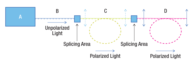
| Fiber | A | B | C | D |
|---|---|---|---|---|
| HB830Z | 830 nm Laser Source |
SM800 Fiber | Coiled HB830Z Fiber | Aligned PM780-HP Fiber |
| HB1060Z | 1060 nm Laser Source |
SM980 Fiber | Coiled HB1060Z Fiber | Aligned PM980-XP Fiber |
| HB1550Z | 1550 nm Laser Source |
SMF-28-J9, CCC1310-J9, 1550BHP, or 1310BHP Fiber |
Coiled HB1550Z Fiber | Aligned PM1550-XP Fiber |
Coiling our PZ fiber to smaller diameters will create a narrower polarization window and blueshift the center wavelength. Coiling the PZ fiber can result in a better polarization extinction ratio, although it can lead to greater loss. If loss is too high, the coil is too tight; conversely, if the polarization extinction ratio is too low, the coil is not tight enough. For example, to achieve an extinction ratio of 35 dB with our HB1060Z PZ Fiber, 2 m of fiber is coiled into Ø5 cm loops. The diagram above demonstrates how this is implemented. Unpolarized light was sent into the PZ fiber, which is coiled to produce the desired effect. The PZ fiber was then spliced into a PM fiber, which goes out to the system. For additional performance stability, it is recommended to use 3 - 5 m of HB1060Z fiber or 4 - 10 m of HB830Z and HB1550Z. However, due to the high birefringence of the PZ fiber, the polarization window will still be broad, giving the user a wide variety of packaging and deployment options.
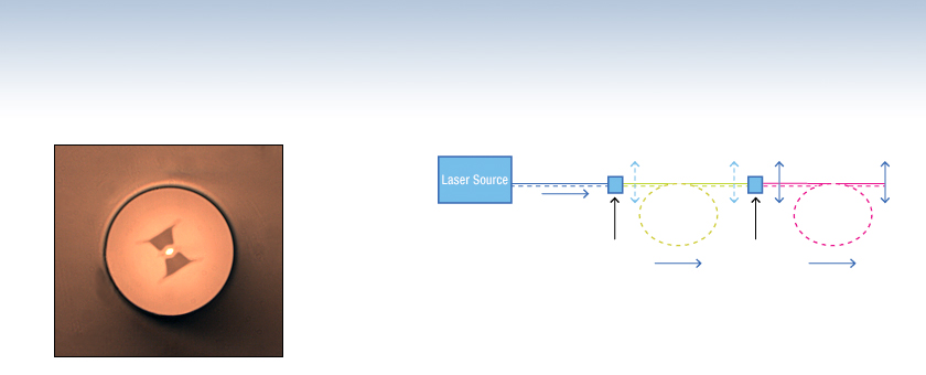
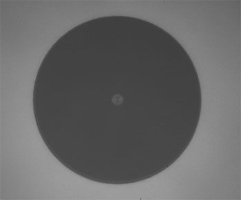
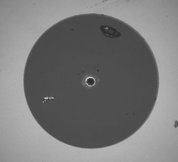
Click to Enlarge
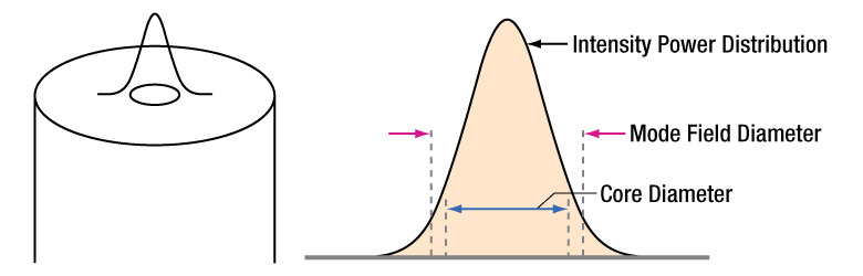
The left image shows the intensity profile of the beam propagated through the fiber overlaid on the fiber itself. The right image shows the standard intensity profile of the beam propagated through the fiber with the MFD and core diameter called out.
Definition of the Mode Field Diameter
The mode field diameter (MFD) is one measure of the beam width of light propagating in a single mode fiber. It is a function of wavelength, core radius, and the refractive indices of the core and cladding. While much of the light in an optical fiber is trapped within the fiber core, a small fraction propagates in the cladding. The light can be approximated as a Gaussian power distribution as shown to the right, where the MFD is the diameter at which the optical power is reduced to 1/e2 from its peak level.
Measurement of MFD
The measurement of MFD is accomplished by the Variable Aperture Method in the Far Field (VAMFF). An aperture is placed in the far field of the fiber output, and the intensity is measured. As successively smaller apertures are placed in the beam, the intensity levels are measured for each aperture; the data can then be plotted as power vs. the sine of the aperture half-angle (or the numerical aperture for an SM fiber).
The MFD is then determined using Petermann's second definition, which is a mathematical model that does not assume a specific shape of power distribution. The MFD in the near field can be determined from this far-field measurement using the Hankel Transform.
| Quick Links |
|---|
| Damage at the Air / Glass Interface |
| Intrinsic Damage Threshold |
| Preparation and Handling of Optical Fibers |
Laser-Induced Damage in Silica Optical Fibers
The following tutorial details damage mechanisms relevant to unterminated (bare) fiber, terminated optical fiber, and other fiber components from laser light sources. These mechanisms include damage that occurs at the air / glass interface (when free-space coupling or when using connectors) and in the optical fiber itself. A fiber component, such as a bare fiber, patch cable, or fused coupler, may have multiple potential avenues for damage (e.g., connectors, fiber end faces, and the device itself). The maximum power that a fiber can handle will always be limited by the lowest limit of any of these damage mechanisms.
While the damage threshold can be estimated using scaling relations and general rules, absolute damage thresholds in optical fibers are very application dependent and user specific. Users can use this guide to estimate a safe power level that minimizes the risk of damage. Following all appropriate preparation and handling guidelines, users should be able to operate a fiber component up to the specified maximum power level; if no maximum is specified for a component, users should abide by the "practical safe level" described below for safe operation of the component. Factors that can reduce power handling and cause damage to a fiber component include, but are not limited to, misalignment during fiber coupling, contamination of the fiber end face, or imperfections in the fiber itself. For further discussion about an optical fiber’s power handling abilities for a specific application, please contact Thorlabs’ Tech Support.
Click to Enlarge
Undamaged Fiber End
Click to Enlarge
Damaged Fiber End
Damage at the Air / Glass Interface
There are several potential damage mechanisms that can occur at the air / glass interface. Light is incident on this interface when free-space coupling or when two fibers are mated using optical connectors. High-intensity light can damage the end face leading to reduced power handling and permanent damage to the fiber. For fibers terminated with optical connectors where the connectors are fixed to the fiber ends using epoxy, the heat generated by high-intensity light can burn the epoxy and leave residues on the fiber facet directly in the beam path.
| Estimated Optical Power Densities on Air / Glass Interfacea | ||
|---|---|---|
| Type | Theoretical Damage Thresholdb | Practical Safe Levelc |
| CW (Average Power) |
~1 MW/cm2 | ~250 kW/cm2 |
| 10 ns Pulsed (Peak Power) |
~5 GW/cm2 | ~1 GW/cm2 |
Damage Mechanisms on the Bare Fiber End Face
Damage mechanisms on a fiber end face can be modeled similarly to bulk optics, and industry-standard damage thresholds for UV Fused Silica substrates can be applied to silica-based fiber. However, unlike bulk optics, the relevant surface areas and beam diameters involved at the air / glass interface of an optical fiber are very small, particularly for coupling into single mode (SM) fiber. therefore, for a given power density, the power incident on the fiber needs to be lower for a smaller beam diameter.
The table to the right lists two thresholds for optical power densities: a theoretical damage threshold and a "practical safe level". In general, the theoretical damage threshold represents the estimated maximum power density that can be incident on the fiber end face without risking damage with very good fiber end face and coupling conditions. The "practical safe level" power density represents minimal risk of fiber damage. Operating a fiber or component beyond the practical safe level is possible, but users must follow the appropriate handling instructions and verify performance at low powers prior to use.
Calculating the Effective Area for Single Mode Fibers
The effective area for single mode (SM) fiber is defined by the mode field diameter (MFD), which is the cross-sectional area through which light propagates in the fiber; this area includes the fiber core and also a portion of the cladding. To achieve good efficiency when coupling into a single mode fiber, the diameter of the input beam must match the MFD of the fiber.
As an example, SM400 single mode fiber has a mode field diameter (MFD) of ~Ø3 µm operating at 400 nm, while the MFD for SMF-28 Ultra single mode fiber operating at 1550 nm is Ø10.5 µm. The effective area for these fibers can be calculated as follows:
SM400 Fiber: Area = Pi x (MFD/2)2 = Pi x (1.5 µm)2 = 7.07 µm2 = 7.07 x 10⁻⁸ cm2
SMF-28 Ultra Fiber: Area = Pi x (MFD/2)2 = Pi x (5.25 µm)2 = 86.6 µm2 = 8.66 x 10⁻⁷ cm2
To estimate the power level that a fiber facet can handle, the power density is multiplied by the effective area. Please note that this calculation assumes a uniform intensity profile, but most laser beams exhibit a Gaussian-like shape within single mode fiber, resulting in a higher power density at the center of the beam compared to the edges. Therefore, these calculations will slightly overestimate the power corresponding to the damage threshold or the practical safe level. Using the estimated power densities assuming a CW light source, we can determine the corresponding power levels as:
SM400 Fiber: 7.07 x 10⁻⁸ cm2 x 1 MW/cm2 = 7.1 x 10⁻⁸ MW = 71 mW (Theoretical Damage Threshold)
7.07 x 10⁻⁸ cm2 x 250 kW/cm2 = 1.8 x 10⁻⁵ kW = 18 mW (Practical Safe Level)
SMF-28 Ultra Fiber: 8.66 x 10⁻⁷ cm2 x 1 MW/cm2 = 8.7 x 10⁻⁷ MW = 870 mW (Theoretical Damage Threshold)
8.66 x 10⁻⁷ cm2 x 250 kW/cm2 = 2.1 x 10⁻⁴ kW = 210 mW (Practical Safe Level)
Effective Area of Multimode Fibers
The effective area of a multimode (MM) fiber is defined by the core diameter, which is typically far larger than the MFD of an SM fiber. For optimal coupling, Thorlabs recommends focusing a beam to a spot roughly 70 - 80% of the core diameter. The larger effective area of MM fibers lowers the power density on the fiber end face, allowing higher optical powers (typically on the order of kilowatts) to be coupled into multimode fiber without damage.
Damage Mechanisms Related to Ferrule / Connector Termination
 Click to Enlarge
Plot showing approximate input power that can be incident on a single mode silica optical fiber with a termination. Each line shows the estimated power level due to a specific damage mechanism. The maximum power handling is limited by the lowest power level from all relevant damage mechanisms (indicated by a solid line).
Fibers terminated with optical connectors have additional power handling considerations. Fiber is typically terminated using epoxy to bond the fiber to a ceramic or steel ferrule. When light is coupled into the fiber through a connector, light that does not enter the core and propagate down the fiber is scattered into the outer layers of the fiber, into the ferrule, and the epoxy used to hold the fiber in the ferrule. If the light is intense enough, it can burn the epoxy, causing it to vaporize and deposit a residue on the face of the connector. This results in localized absorption sites on the fiber end face that reduce coupling efficiency and increase scattering, causing further damage.
For several reasons, epoxy-related damage is dependent on the wavelength. In general, light scatters more strongly at short wavelengths than at longer wavelengths. Misalignment when coupling is also more likely due to the small MFD of short-wavelength SM fiber that also produces more scattered light.
To minimize the risk of burning the epoxy, fiber connectors can be constructed to have an epoxy-free air gap between the optical fiber and ferrule near the fiber end face. Our high-power multimode fiber patch cables use connectors with this design feature.
Determining Power Handling with Multiple Damage Mechanisms
When fiber cables or components have multiple avenues for damage (e.g., fiber patch cables), the maximum power handling is always limited by the lowest damage threshold that is relevant to the fiber component. In general, this represents the highest input power that can be incident on the patch cable end face and not the coupled output power.
As an illustrative example, the graph to the right shows an estimate of the power handling limitations of a single mode fiber patch cable due to damage to the fiber end face and damage via an optical connector. The total input power handling of a terminated fiber at a given wavelength is limited by the lower of the two limitations at any given wavelength (indicated by the solid lines). A single mode fiber operating at around 488 nm is primarily limited by damage to the fiber end face (blue solid line), but fibers operating at 1550 nm are limited by damage to the optical connector (red solid line).
In the case of a multimode fiber, the effective mode area is defined by the core diameter, which is larger than the effective mode area for SM fiber. This results in a lower power density on the fiber end face and allows higher optical powers (on the order of kilowatts) to be coupled into the fiber without damage (not shown in graph). However, the damage limit of the ferrule / connector termination remains unchanged and as a result, the maximum power handling for a multimode fiber is limited by the ferrule and connector termination.
Please note that these are rough estimates of power levels where damage is very unlikely with proper handling and alignment procedures. It is worth noting that optical fibers are frequently used at power levels above those described here. However, these applications typically require expert users and testing at lower powers first to minimize risk of damage. Even still, optical fiber components should be considered a consumable lab supply if used at high power levels.
Intrinsic Damage Threshold
In addition to damage mechanisms at the air / glass interface, optical fibers also display power handling limitations due to damage mechanisms within the optical fiber itself. These limitations will affect all fiber components as they are intrinsic to the fiber itself. Two categories of damage within the fiber are damage from bend losses and damage from photodarkening.
Bend Losses
Bend losses occur when a fiber is bent to a point where light traveling in the core is incident on the core/cladding interface at an angle higher than the critical angle, making total internal reflection impossible. Under these circumstances, light escapes the fiber, often in a localized area. The light escaping the fiber typically has a high power density, which burns the fiber coating as well as any surrounding furcation tubing.
A special category of optical fiber, called double-clad fiber, can reduce the risk of bend-loss damage by allowing the fiber’s cladding (2nd layer) to also function as a waveguide in addition to the core. By making the critical angle of the cladding/coating interface higher than the critical angle of the core/clad interface, light that escapes the core is loosely confined within the cladding. It will then leak out over a distance of centimeters or meters instead of at one localized spot within the fiber, minimizing the risk of damage. Thorlabs manufactures and sells 0.22 NA double-clad multimode fiber, which boasts very high, megawatt range power handling.
Photodarkening
A second damage mechanism, called photodarkening or solarization, can occur in fibers used with ultraviolet or short-wavelength visible light, particularly those with germanium-doped cores. Fibers used at these wavelengths will experience increased attenuation over time. The mechanism that causes photodarkening is largely unknown, but several fiber designs have been developed to mitigate it. For example, fibers with a very low hydroxyl ion (OH) content have been found to resist photodarkening and using other dopants, such as fluorine, can also reduce photodarkening.
Even with the above strategies in place, all fibers eventually experience photodarkening when used with UV or short-wavelength light, and thus, fibers used at these wavelengths should be considered consumables.
Preparation and Handling of Optical Fibers
General Cleaning and Operation Guidelines
These general cleaning and operation guidelines are recommended for all fiber optic products. Users should still follow specific guidelines for an individual product as outlined in the support documentation or manual. Damage threshold calculations only apply when all appropriate cleaning and handling procedures are followed.
-
All light sources should be turned off prior to installing or integrating optical fibers (terminated or bare). This ensures that focused beams of light are not incident on fragile parts of the connector or fiber, which can possibly cause damage.
-
The power-handling capability of an optical fiber is directly linked to the quality of the fiber/connector end face. Always inspect the fiber end prior to connecting the fiber to an optical system. The fiber end face should be clean and clear of dirt and other contaminants that can cause scattering of coupled light. Bare fiber should be cleaved prior to use and users should inspect the fiber end to ensure a good quality cleave is achieved.
-
If an optical fiber is to be spliced into the optical system, users should first verify that the splice is of good quality at a low optical power prior to high-power use. Poor splice quality may increase light scattering at the splice interface, which can be a source of fiber damage.
-
Users should use low power when aligning the system and optimizing coupling; this minimizes exposure of other parts of the fiber (other than the core) to light. Damage from scattered light can occur if a high power beam is focused on the cladding, coating, or connector.
Tips for Using Fiber at Higher Optical Power
Optical fibers and fiber components should generally be operated within safe power level limits, but under ideal conditions (very good optical alignment and very clean optical end faces), the power handling of a fiber component may be increased. Users must verify the performance and stability of a fiber component within their system prior to increasing input or output power and follow all necessary safety and operation instructions. The tips below are useful suggestions when considering increasing optical power in an optical fiber or component.
-
Splicing a fiber component into a system using a fiber splicer can increase power handling as it minimizes possibility of air/fiber interface damage. Users should follow all appropriate guidelines to prepare and make a high-quality fiber splice. Poor splices can lead to scattering or regions of highly localized heat at the splice interface that can damage the fiber.
-
After connecting the fiber or component, the system should be tested and aligned using a light source at low power. The system power can be ramped up slowly to the desired output power while periodically verifying all components are properly aligned and that coupling efficiency is not changing with respect to optical launch power.
-
Bend losses that result from sharply bending a fiber can cause light to leak from the fiber in the stressed area. When operating at high power, the localized heating that can occur when a large amount of light escapes a small localized area (the stressed region) can damage the fiber. Avoid disturbing or accidently bending fibers during operation to minimize bend losses.
-
Users should always choose the appropriate optical fiber for a given application. For example, large-mode-area fibers are a good alternative to standard single mode fibers in high-power applications as they provide good beam quality with a larger MFD, decreasing the power density on the air/fiber interface.
-
Step-index silica single mode fibers are normally not used for ultraviolet light or high-peak-power pulsed applications due to the high spatial power densities associated with these applications.
| Posted Comments: | |
user
(posted 2024-05-22 14:10:34.34) Any plan for the O-band? cdolbashian
(posted 2024-05-22 04:41:34.0) Thank you for reaching out to us with this inquiry. As of now we do not have a plan for it, but I have submitted this request to our internal product development forum for review. Thank you for the interest and suggestion! Miguel Ribera Vicent
(posted 2023-09-11 08:08:38.67) Hello Thorlabs team,
My comment is not feedback itself, but rather a doubt that is unclear to me about the product, "Polarizing optical fiber".
I am not clear about the direction of propagation of the polarization. It is said that it will only propagate in one direction, but which one is it?
From the graphs that you put, it is deduced that it is the one that propagates along the slow axis of the fiber. But in terms of the electric field, which would be this direction, the one aligned with this axis or its perpendicular?
I hope the question is understood. Thank you!!
Best regards,
Miguel jpolaris
(posted 2023-09-14 03:57:35.0) Thank you for contacting Thorlabs. Your understanding of the propagation axis is correct. Light propagates down the slow axis because above the Fast Edge wavelength, attenuation in the fast axis is very large (e.g., < -20 dB). At the Fast Edge wavelength, the attenuation in the slow axis is minimal and approximately constant with respect to wavelength. As wavelength increases further, there will be a point where the attenuation in the slow axis begins to grow. The point at which the slow axis attenuation reaches -3 dB defines the Slow Edge wavelength. Please note that typical polarization performance is with deployment conditions of 5 m fiber length in a Ø89 mm (Ø3.5") coil. In terms of the electric field, this fiber will only transmit polarization states in which the electric field is parallel with the slow axis. Any electric field components orthogonal to the slow axis will be heavily attenuated. Danny Nguyen
(posted 2022-07-18 13:54:44.33) This is a generic comment and not directed toward any specific product. I believe your tutorial on PZ fiber has a critical error. To make depolarizer, you need to splice 2 PM fibers at 45o. Splicing 2 SM fiber at 45o will produce nothing, and will have no effect on polarization state of the light. ppestre
(posted 2022-07-26 02:07:25.0) Thank you for your feedback! This has now been corrected to say PM fiber for the depolarizer. teraoka
(posted 2017-02-01 09:43:08.35) HB1550Z 1550 nm 125 ± 1 µm 245 ± 15 µm 10.0 - 12.5 µm
@ 1550 nm 0.09 - 0.11 1550 nm:
1.64263g 1550 nm:
1.63985g
This fiber is not a silica fiber? What is it made of? tcampbell
(posted 2017-02-03 10:02:19.0) Response from Tim at Thorlabs: Thank you for your feedback. This fiber has a germanosilicate core (Ge-doped silica). That is all the information we can provide on the fiber composition at this time. ak-suzuki
(posted 2016-08-02 12:42:03.017) My name is Akinori Suzuki, resercher from Magnescale in Japan.
Please refer to our company's profile from the following link.
http://www.magnescale.com/mgs/language/english/
We develop and sell many kinds of positioning sensor for precision processing machine in Japan.
We are strongly interested in polarizing fiber (HB830Z).
We want to order the product because it can solve some problems that our clients have.
As we would like to judge if it can solve the problems before we place an order officially, would you provide details as bellow
1.PZ fiber ER at random deployment or straight deployment.
2. How to deploy fast axis(or slow axis) to fiber coil plane. user
(posted 2013-02-23 01:59:17.947) Polarizing fiber and Polarizing fiber patch cords for wavelength from 780 nm to 852 nm will be useful. cdaly
(posted 2013-03-06 14:16:00.0) Response from Chris at Thorlabs: At the moment we are still looking into providing this as a stock component, but in the meantime we may be able to offer it as a custom. I will contact you directly to discuss this further. jlow
(posted 2012-08-09 09:38:00.0) Response from Jeremy at Thorlabs: The polarizing fiber for that wavelength range is currently under development but may not be available in the near future. With regard to supplying the fiber with FC connector, we are currently looking into adding this to our regular offering. In the meantime, we can make these to order. I will get in contact with you directly regarding this. parkse
(posted 2012-08-07 07:56:18.0) Please supply polarizing fiber operating from 780 nm to 850 nm range. And also supply PZ fiber patch calbes with FC connectors. |