Few Input Polarization States are Preserved by Polarization Maintaining Fiber


Please Wait
Does PM fiber preserve every input polarization state?
No polarization-maintaining (PM) fiber preserves an arbitrary input polarization state. Typical PM fiber only preserves the polarization state of input light that is both linearly polarized and polarized parallel to one of the fiber's two orthogonal axes. The orientation of the linearly polarized light input to the PM fiber matters, since the refractive indices of its two orthogonal axes are different. Light polarized along the high-index direction (slow axis) travels more slowly than light polarized along the orthogonal direction (fast axis).
If the input polarization state does not meet these criteria, the light output from the fiber will be elliptically polarized. However, the elliptical polarization state cannot be predicted and is not stable, since it depends on the fluctuating temperature and stress conditions over the length of the fiber.

Click to Enlarge
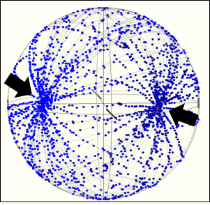
Figure 1: Polarimeter measurements of light output by a PM fiber patch cable are plotted on a Poincaré sphere. The points indicated by the arrows result when there is optimal alignment between the linearly polarized input and one of the fiber's axes. These input states are preserved by the fiber. All other points correspond to the elliptically polarized output states resulting when the input light's polarization direction is not parallel with one of the fiber's axes.
PM Fibers Do Not Polarize Light
A PM fiber does not behave like a linear polarizer, and a PM fiber will not convert an arbitrary input polarization state into a linearly polarized output state.
A linear polarizer has two orthogonal axes, but these are not the slow and fast axes of a PM fiber. In the case of a linear polarizer, the light polarized parallel to one of the axes is attenuated, while the light polarized parallel to the other is transmitted. Since only one polarization component is transmitted, the output light is linearly polarized.
Because a PM fiber transmits both orthogonal polarization components, instead of attenuating one, PM fiber cannot be used as a linear polarizer.
Comparison with Wave Plates
Since PM fibers and wave plates both have fast and slow axes, they have a lot in common. If the polarization axis of a linearly polarized light beam is aligned parallel to either the slow or the fast axis, both PM fibers and wave plates will preserve that polarization state. However, if the input beam has components polarized along both slow and fast axes, neither a PM fiber nor a wave plate will preserve the input polarization state.
Both PM fibers and wave plates change the polarization state of a light beam by delaying the component of light polarized parallel to the slow axis more than the component polarized parallel to the fast axis. But, a PM fiber cannot be used to replace a wave plate, since the delay induced by the PM fiber fluctuates unpredictably as the temperature and stress applied over the length of the fiber changes.
Output Polarization States
The polarimeter measurements plotted on the Poincaré sphere in Figure 1 illustrate the range of elliptically polarized output states a PM fiber patch cable can provide, when the input is a linearly polarized beam with arbitrary orientation to the fiber's axes. The polarimeter measurement of the output light has one of the two values indicated by the black arrows, when the fiber preserves the input polarization state. These values result when there is optimal alignment between the polarization direction of the input polarization state and one of the fiber's axes. All other points on the sphere indicate elliptical output polarization states occurring when the input polarization state is not aligned parallel to either fiber axis.
Each data trace in the figure was generated by rotating the polarization direction of the linearly polarized input light once around the optical axis. The traces do not overlap, since the temperature of the fiber was changed after every rotation. Each temperature change resulted in a different set of elliptically polarized output states, due to the fiber's temperature sensitivity. Note that each data trace crosses the points indicated by the arrows. This indicates that when the linearly polarized input state is well-aligned to one of the fiber's axes, the output polarization state is not sensitive to changes in temperature and applied stress.
|
Looking for more Insights? |
Date of Last Edit: Aug. 6, 2020 |
| Posted Comments: | |
Chad Brubaker
(posted 2024-10-15 10:26:03.26) I curious - what would happen if you couple one PM fiber (using an FC/APC connector, for example) with slow axis aligned to the key (standard configuration for Thorlabs PM fiber devices, as near as I can tell) to another fiber that has the fast axis aligned to the key? In my limited understanding, it looks like both polarization states (TE and TM) are preserved as long as they are aligned to begin with, and that the specific polarization axis is not affected by the stress axis (i.e., TE can be maintained along fast or slow axis; if you introduce the TE axis to the fast axis, it will remain aligned to the fast axis; if it is introduced to the slow axis it will still remain aligned tot he slow axis).
Would there be some sort of disruptive effect, or will this act to effectively "rotate" the polarization state compared to the fast/slow axes? EGies
(posted 2024-10-16 02:31:48.0) Thank you for contacting Thorlabs. If you have linearly polarized light aligned to the slow axis of a polarization maintaining (PM) fiber whose connector key is also aligned to the slow axis, then mate that fiber to another PM fiber whose connector key is aligned to the fast axis, the polarization will be maintained and aligned to the fast axis of the second fiber. I have reached out to you directly regarding this. |
 Products Home
 Polarization States Preserved by PM Fiber