 Products Home / Technical Resources / Insights / Device Function Insights / Post Holder's Inner Bore Has Channel to Seat Posts Stably and Repeatably
Post Holder's Inner Bore Has Channel to Seat Posts Stably and Repeatably


Please Wait
Post Holders: Rectangular Channel in the Inner Bore
Click to Enlarge
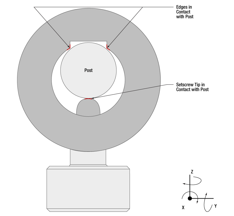
Figure 2: Top view. The three contact locations between the post and post holder, highlighted in red, prevent the post from translating or rotating around the x- or y-axes. Friction resists the post's translation and rotation around the z-axis.

Click to Enlarge
Figure 1: A channel with sharp edges is machined into the inner bore of Thorlabs' post holders.
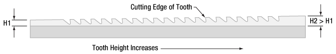
Figure 3: A broach, such as the one illustrated above, has a row of teeth, the next taller than the previous. With the teeth in contact with the material, a machine pulls the broach across the surface. Each tooth removes a small amount of material, and the depth of the channel created by the broach equals the overall difference in tooth height.
All of Thorlabs' post holders include a channel, with straight parallel edges, running the length of the inner bore (Figure 1). Tightening the setscrew pushes the post against the two edges of the channel (Figure 2). Since the edges of the channel are separated by a wide distance, approximately half the inner diameter of the post holder, the seating of the post against the channel's edges is stable and repeatable.
Contact with the two edges of the channel eliminates four of the post's six degrees of freedom, since the edges block the post from translating along or rotating around either the y- or z-axis. In addition, the friction between the side of the post and the edges of the channel resists the post's movement along and around the x-axis, which are the post's two remaining degrees of freedom.
Without the channel in the inner bore, there would be a single line of contact between the post and post holder. The position of the post would not be stable, since the post would be free to rotate around the z-axis and shift along the y-axis.
Even if this instability resulted in submicron-scale unwanted shifts in each component's position in an optical setup, the cumulative effect could have a significant negative impact on system performance. In addition, more frequent realignment of the system could be required.
Broaching
The channel's edges must be straight and free of bumps and roughness to hold the post stable. These post holders have straight, sharp edges when examined on a micron scale. If the edges are not completely linear, the post might rock in the holder, and / or it may not be possible to repeatably position the post in the holder.
The smooth, straight edges of the channel are achieved using a machining process called broaching. A broach (Figure 3) resembles a saw whose teeth increase in height along its length.
As the broach is pulled along a surface, each tooth removes a small amount of material. The total depth of the channel cut by the broach equals to the overall difference in tooth height (H2 - H1 ).
Compared with other approaches for creating channels, broaching is preferred due to its ability to provide straight profiles while being compatible with high-volume production.
|
Looking for more Insights? |
Date of Last Edit: Dec. 11, 2019 |
| Posted Comments: | |
| No Comments Posted |