Using the Poincare Sphere to Represent the Polarization State


Please Wait
How is a Poincare Sphere useful for representing polarization states?

Click to Enlarge
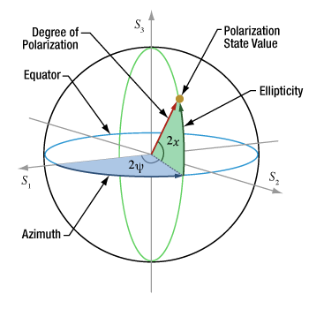
Figure 1: Polarization states are mapped to the Poincaré sphere using azimuthal and ellipticity angles, from the S1 axis and the equator, respectively. The state's radius is largest when the light is completely polarized (no fraction is unpolarized).

Click to Enlarge
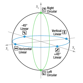
Figure 2: States (blue circles) mapped to the equator (blue curve) of the spherical surface are perfectly linearly polarized. States (green circles) mapped to a value of ±1 on the S3 axis are circularly polarized. All elliptical polarization states that are not linearly or circularly polarized are mapped to other regions of the sphere.
Polarization states are mapped to the Poincaré sphere using an approach similar to the system of latitude and longitude used to locate points on the Earth's globe. The coordinates of points across and within the Poincarré sphere are specified using two angular values (azimuth and ellipticity) and a radius. The azimuth and ellipticity parameters are taken from the polarization ellipse representation of the polarization state. The radius is determined by the light's degree of polarization and has a maximum value of one, which corresponds to perfectly polarized light.
Both the Poincaré sphere and polarization ellipse are useful for visualizing a polarization state and observing its evolution. However, a key benefit of the spherical representation is that it simplifies the math needed to calculate incremental changes in polarization state.
Data Points on the Poincaré Sphere
The azimuthal angle  /2
/2 /4
/4
A radius of one corresponds to the surface of the sphere and indicates the light is completely polarized. The radius decreases as the fraction of unpolarized light increases. The degree of polarization (DOP) is the intensity of polarized light divided by the total light intensity.
The Stokes parameters (S1, S2, S3) of the polarization state correspond to the state's Cartesian coordinates (see the table below).
From One State to Another
Any two polarization state values plotted on the surface of the Poincaré sphere can be connected by a single arc, and the difference in the two states' azimuth and ellipticity can be calculated using spherical trigonometry. This provides a convenient way to predict the polarization state of light after interaction with a polarizing element, as well as to determine the azimuth and ellipticity of the polarizing element required to provide a desired polarization state.
| Cartesian to Poincaré Sphere Coordinates | |||
| S1 = cos(2χ)*cos(2ψ) | |||
| S2 = cos(2χ)sin(2ψ) | |||
| S3 = sin(2χ) | |||
| Selected Polarization States | Azimuth/2a | Ellipticity/2a | (S1, S2, S3) |
| Horizontal Linear | ψ = 0 | χ = 0 | (1, 0, 0) |
| +45° Linear | ψ = /4 /4 |
χ = 0 | (0, 1, 0) |
| Vertical Linear | ψ =  /2 /2 |
χ = 0 | (-1, 0, 0) |
| -45° Linear | ψ = 3 /4 /4 |
χ = 0 | (0, -1, 0) |
| Right Circular | ψ = 0 | χ =  /4 /4 |
(0, 0, 1) |
| Left Circular | ψ = 0 | χ = - /4 /4 |
(0, 0, -1) |
References
[1] Edward Collett, Polarized Light in Fiber Optics (Elsevier, Inc., New York, 2007) pp. 45-53.
[2] Russell A. Chipman, Wai-Sze Tiffany Lam, and Garam Young, Polarized Light and Optical Systems (CRC Press, New York, 2019) pp. 80-83.
Date of Last Edit: Sept. 11, 2020
|
Looking for more Insights? |
Date of Last Edit: July 21, 2020 |
| Posted Comments: | |
| No Comments Posted |
 Products Home
 Poincare Sphere