The Polarization Ellipse Representation of the Polarization State


Please Wait
How is the polarization ellipse related to the polarization state?

Click to Enlarge
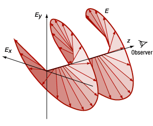
Figure 2: As the electric field ( ) propagates, the tip of the vector follows a helical path. In this case, propagation is along the z-axis, and the helicity of the path followed by the
  vector is positive (clockwise rotation).

Click to Enlarge
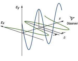
Figure 1: The electric field ( ) can be expressed as the sum of two orthogonal components (Ex and Ey ), with a phase shift

Click to Enlarge
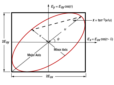
Figure 3: If an observer looks into the beam propagating from the origin in Figure 2, the tip of the rotating electric field vector traces out an ellipse. The ellipse can be described in terms of angles Ψ and χ. The equations in this figure use ( ) to represent (
  /λ - ωt ), where λ is the material-dependent wavelength, ω is frequency, and t is time.
The polarization ellipse is a way to visualize the polarization state.
As a laser beam propagates, the tip of its electric field vector moves along a three dimensional path determined by the polarization state. If an observer looking into the beam could see the electric field advancing in real time, the vector's tip would appear to cycle around the propagation axis while following a two-dimensional, elliptical track.
The shape of this track is the polarization ellipse, which becomes a line for linearly polarized light and a circle for circularly polarized light.
Components of Light
The electric field vector ( ) can be described by its orthogonal components, Ex and Ey . Figure 1 illustrates a case of elliptically polarized light, in which the polarization is not linear or circular. The Ex and Ey components have different amplitudes, and the phase difference (δ ) between the Ex and Ey components is not an integer multiple of
  /2. The Ex and Ey components' values increase and decrease periodically, but they vary out of sync with one another and span different ranges.
If the orthogonal components were added together as vectors, the total  field vector would rotate around the propagation axis as it traveled (Figure 2), and its length would vary with the rotation angle. Looking into the beam, perpendicular to the Ex - Ey plane, the tip of the
  vector would trace out the curve of the polarization ellipse (Figure 3).
Polarization Ellipse
An observer looking into the beam will describe a different polarization ellipse than an observer facing the opposite direction. Due to this, it is necessary to specify the direction the observer faces. Here, the observer is assumed to be looking into the beam.
The polarization ellipse is bound by a rectangle whose sides are equal to twice the amplitudes, Eox and Eoy , of the Ex and Ey components, respectively. This rectangle provides information about the fraction of the light contained in each orthogonal component.
To determine the specific characteristics of the polarization ellipse corresponding to a polarization state, the phase delay between the Ex and Ey components must also be considered. Key characteristics of the ellipse providing polarization state information are the rotation of the major axis with respect to the Ex axis and the relative lengths of the minor and major axes.
The angle (ψ ) between the major axis of the ellipse and the Ex axis is known by many names, including orientation angle, angle of inclination, rotation, tilt, and azimuth. It varies between -90° and 90°, and it is ±45° when Eox and Eoy have equal magnitudes.
The ellipticity of the polarization ellipse is the ratio (ε ) between the lengths of the minor and major axes. Since the orientation is typically stated as an angle, it can be convenient to also express ellipticity as an angle ( χ ). The ellipticity has a range of values from zero ( χ = 0°) for linearly polarized light, which is the case for δ = 0, to one ( χ = 45°) for circularly polarized light, which is the case for δ =  /2.
/2.
The tip of the electric field vector may rotate in a right-hand (clockwise) or left-hand (counterclockwise) direction as it propagates. This is known as the handedness or helicity of light, in which right-hand polarized light has positive helicity and left-hand polarized light has negative helicity. The direction can be determined using values of the E vector at time equal to zero (Et=0 ) and at a time one quarter of a period (T ) later (Et=T/4 ). If the cross product (

Click for Details
Figure 4: The ellipticity and orientation of the polarization ellipse provides information about the phase shift (δ ) between the Ex and Ey components of the electric field. The ellipses shown above result when the peak amplitudes of both components are the same. The direction of the E vector's rotation is indicated by the direction of the arrow on the polarization ellipse. Click the image to see ellipticity and orientation angles for each case.
|
Looking for more Insights? |
Date of Last Edit: July 7, 2020 |
| Posted Comments: | |
| No Comments Posted |
 Products Home
 Polarization Ellipses