 Products Home / Technical Resources / Insights / Device Function Insights / Identify the Bottom of the Optical Base by Locating the Undercut
Identify the Bottom of the Optical Base by Locating the Undercut

Please Wait
Bases: For Stability Orient the Side with the Undercut Down
Click to Enlarge
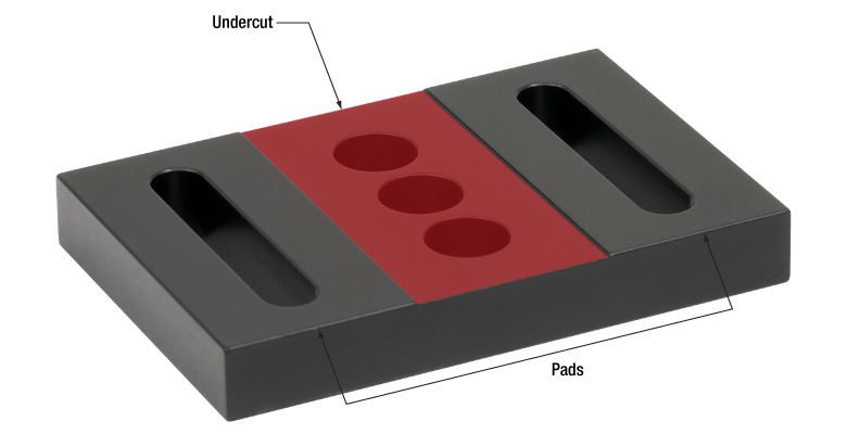
Figure 2: This view of the bottom shows the undercut highlighted in red. By removing this material, the pads can be made maximally flat.
Click to Enlarge
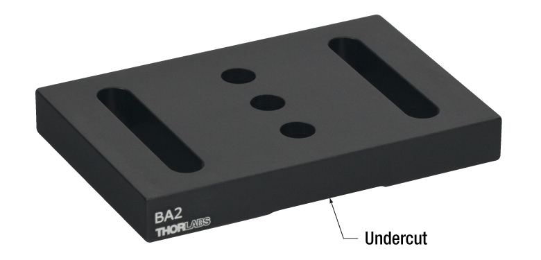
Figure 1: For optimal stability, the base should be mounted with the undercut facing the optical table or breadboard.
Click to Enlarge
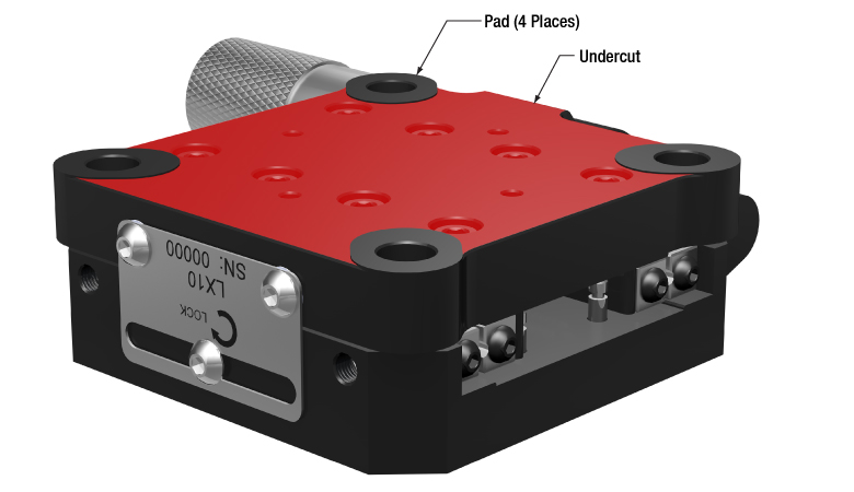
Figure 4: Pads machined into Thorlabs' devices improve their stability when bolted in place. The pads are highly flat and project above the undercut region, which is highlighted red. The undercut limits the contact area with the table or breadboard.
Click to Enlarge
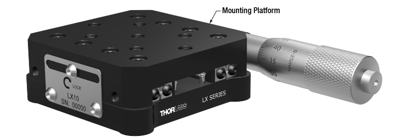
Figure 3: The mounting platforms of stages and other devices do not feature pads.
An undercut is machined into the bottom surface of bases like the BA2 (Figures 1 and 2). The undercut creates feet, which are called pads. For maximum stability, the base should be oriented with its pads in contact with the table or breadboard.
The top surface of the base does not have an undercut and is the intended mounting surface for components.
Mounting the base upside down could result in the base rocking on the table or breadboard, or the base may exhibit other mechanical instability.
The Pads are Flatter than the Top Surface
The undercut is key to the flatness of the pads. The pads are machined flat after the undercut is made.
Friction heats the pads during the processing step that provides them with a maximally flat profile. By reducing the surface area of the pads, the undercut reduces the amount of heat generated during this step.
It is beneficial to minimize the heat generated during machining. Metal expands when heated, and the uneven heating that occurs during machining can distort the dimensions of the part. If the dimensions of the part are distorted during machining, the part can be left with high spots and other undesirable features after it cools. This can cause instability and misalignment when using the part.
Precision Instruments and Devices have Pads
Another example of a component with pads is the LX10 linear stage shown in Figures 3 and 4.
|
Looking for more Insights? |
Date of Last Edit: Dec. 9, 2019 |
| Posted Comments: | |
| No Comments Posted |