Polarization Performance of Metal-Coated Corner-Cube Retroreflectors


Please Wait
Why coat the backsides of solid prism retroreflectors with metal?
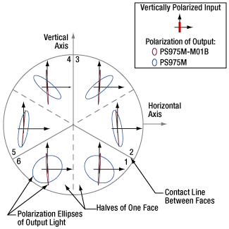
Click for Details
Figure 2: Vertically polarized beams were input to a TIR solid prism retroreflector (PS975M) and a backside-gold-coated solid prism retroreflector (PS975M-M01B). The polarization ellipse of each output beam is shown in the zone that provided the beam's third reflection. For a plot of the ellipticity angle ( χ ) and orientation angles ( ψ ) with respect to the horizontal axis, click here.
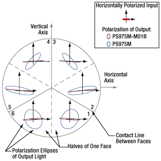
Click to Enlarge
Figure 1: Horizontally polarized beams were input to a TIR solid prism retroreflector (PS975M) and a backside-gold-coated solid prism retroreflector (PS975M-M01B). The polarization ellipse of each output beam is shown in the zone that provided the beam's third reflection. For a plot of the ellipticity angles ( ψ ) with respect to the horizontal axis, click here.
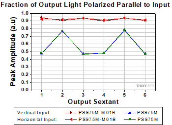
Click to Enlarge
Figure 4: Retroreflectors convert some of the input light to the orthogonal polarization. Over 90% of the light output from the backside-gold-coated solid prism retroreflector (PS975M-M01B) remained polarized in the input state. In the case of the TIR solid prism retroreflector (PS975M), that percentage strongly depended on beam path and did not exceed 80%.
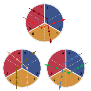
Click to Enlarge
Figure 3: A retroreflector is designed to reflect an input beam once off of each face. When the beam is approximately normal to the viewing plane illustrated in Figures 1 and 2, the beam will follow one of six beam paths.
When the backsides of solid prism retroreflectors are coated with metal, polarization changes induced in the output beam are significantly reduced.
This is due to the difference between specular reflections, which occur from interfaces between glass and the higher refractive index metal, and reflections that occur due to total internal reflection (TIR), which require the backside material, like air, to have a lower refractive index.
Compared with TIR, a specular reflection from a glass-metal interface better preserves the input beam's polarization ellipticity.
Polarization and Beam Path Diagrams
Beam paths through a retroreflector can be described by dividing its three reflective faces into six wedge-shaped zones (Figures 1, 2 and 3). Solid gray boundary lines mark physical lines of contact between reflective faces. Dotted gray lines indicate boundaries between the halves of each face.
The retroreflectors in these figures are oriented with one face-to-face interface aligned with the vertical axis. When the input beam is normal to these figures' viewing planes, Figure 3 describes the order in which the input beam reflects from the three faces before being output.
Output Polarization State
Two sets of six measurements were made for both a PS975M TIR solid prism retroreflector and a
In Figures 1 and 2, the polarization states of the output beam are represented using polarization ellipses. Each output beam's polarization ellipse is shown in the zone that provided the third reflection.
Ideally, the output beam would have the same polarization state as the input beam. However, these measurements indicate the retroreflectors converted some of the incident light to the orthogonal polarization. The plot in Figure 4 is a measure of the fraction of light in the output beam that was polarized parallel to the input.
The backside-gold-coated solid prism retroreflector was significantly more successful in maintaining the polarization state of these linearly polarized input beams.
|
Looking for more Insights? |
Date of Last Edit: July 7, 2020 |
| Posted Comments: | |
| No Comments Posted |
 Products Home
 Retroreflectors and Output Polarization State