 Products Home / Optical Power and Energy Meters / Digital Handheld Optical Power and Energy Meter Consoles
Digital Handheld Optical Power and Energy Meter Consoles
- Power and Energy Measurements for Free Space and Fiber Applications
- Designed for High Accuracy, Reliability, and Ease of Use
- Over 40 Compatible Power or Energy Sensors
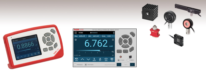
PM100D2
Power and Energy Meter Console
Interactive GUI Available to Demo All Features of the Consoles with Different Sensors
Sensor Options
Photodiode, Fiber, Integrating Sphere, Thermal Power, Thermal Position, and Pyroelectric Energy Sensors Available


Please Wait
| PM100D2 and PM100D3 Feature Comparison | ||
|---|---|---|
| Item # | PM100D2 | PM100D3 |
| 3.5" IPS Capacitive Touchscreen Color Display |  |
|
| Rubber Protection, Foldable Stand, and 1/4-20" Post Mounting | |
|
| Fast Charging Battery via USB-C | |
|
| 8 GB Internal Flash Memory with USB Access | |
|
| Smart Analog Output | |
|
| Compatible with OPM Software | |
|
| Compatible Sensors | ||
| Photodiode Power Sensors | |
|
| Thermal Power Sensors | |
|
| Thermal Position and Power Sensors | - | |
| Pyroelectric Energy Sensors | |
|
| Measurement Screens | ||
| Numerical with Bar Graph Screen | |
|
| Simulated Analog Needle Screen | |
|
| Data Logging Line Graph Screen | |
|
| Data Logging Statistics Screen | |
|
| Pass/Fail Analysis Screen | - | |
| Scope Mode Screen | - | |
| Additional Features | ||
| Embedded Wireless Charging Coil (Charger Not Included) | - | |
| Admin and Two User Settings | - | |
| Physical Menu Button Configuration | - | |
| Bluetooth Low Energy Connectivity | - | |
| Auxiliary Functions Connector | - | |
| Softshell Storage Bag for Console and Sensors | - | |
| Power Meter Selection Guide |
|---|
| Sensors |
| Photodiode Power Sensors |
| Thermal Power Sensors |
| Thermal Position & Power Sensors |
| Pyroelectric Energy Sensors |
| Power Meter Consoles |
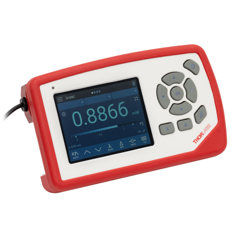
| Digital Handheld Consoles |
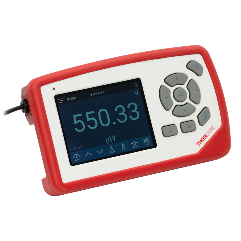
| Analog Handheld Console |
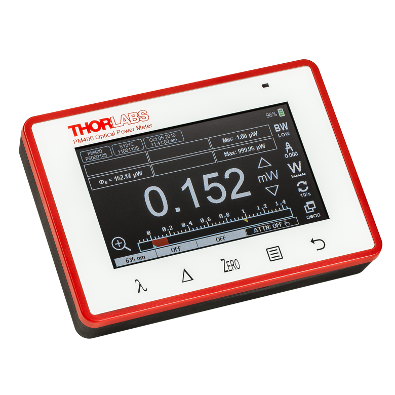
| Touchscreen Handheld Console |
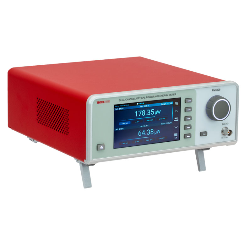
| Dual-Channel Benchtop Console |
| Complete Power Meters |
| Power Meter Bundles |
| Wireless Power Meters with Sensors |
| Compact USB Power Meters |
| Field Power Meters for Terminated Fibers |
| USB Interfaces, External Readout |
Features
- Coherent or Incoherent Light Source Measurements
- Power or Energy Measurements for CW or Pulsed Source Detection
- Fast Bandwidth of Up to 100 kHz (Sensor Dependent)
- User Interface Includes a 3.5" Color Touchscreen Display and Physical Buttons with Multiple Display Screens:
- Numerical with Bar Graph, Simulated Analog Needle, Statistics, or Data Logging Screens for Power or Energy (Sensor Dependent)
- Pass/Fail Analysis or Scope Screens (Item # PM100D3 Only)
- Apply User-Provided Spectral Calibration and Attenuation Correction to Measurements
- Compatible with Over 40 Photodiode and Thermal Power and Pyroelectric Energy Sensors (Sold Below)
- Detect Average or Peak Power with Photodiode Sensors
- Compatible with Thermal Position & Energy Sensors (Sold Below, Item # PM100D3 Only)
- Interactive Demo Available for Both Consoles with Photodiode or Thermal Sensors (See Interactive Demo Tab)
- 8 GB Flash Memory for Storing Data and Transferring to PC via USB 2.0
- Internal Li-Polymer Battery Lasts for a Full Workday, Rechargeable with USB-C (Both Versions) or Embedded Wireless Charging Coil (Item # PM100D3 Only)
- Configurable SMA Analog Output (Both Versions) and 26-Pin AUX Connector (Item # PM100D3 Only)
- Sensor and Power Meter Console Recalibration Services Available
- Optical Parameter Monitor (OPM) PC Software Available (See Software Tab for Details)
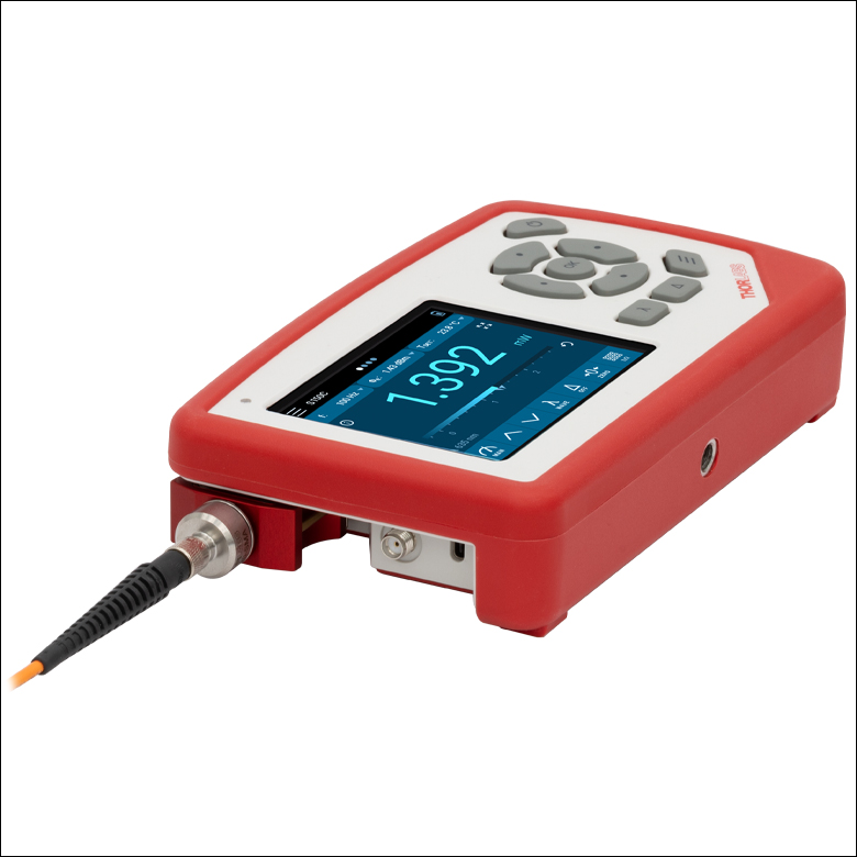
The PM100D2 and PM100D3 Optical Power and Energy Meter Consoles are the cornerstone of Thorlabs' optical power and energy meters and are the digital counterparts to the PM100A analog power meter console. The consoles (and sensors, sold separately) are ideal for use as CW and pulsed source power meters, incoherent optical source power meters, general light power meters, fiber power meters, and more. The display on the PM100Dx power meter features adjustable brightness settings and the option of using a dark, bright, or black background.
The PM100D2 and PM100D3 consoles are compatible with more than 40 photodiode, slim photodiode, integrating sphere, fiber, thermal, and pyroelectric sensors designed for use from the UV to the Mid-IR, with a bandwidth of up to 100 kHz, depending on the sensor and settings. The PM100D3 console is also compatible with our thermal position and power sensors. See the Sensor Selection tab for more information on compatible sensors, available for purchase below.
For a compact power meter console with exclusively touch controls, we offer the PM400 capacitive touchscreen power and energy meter console. Please see the Console Selection tab for a side-by-side comparison of our power meter consoles and their features. We also offer wireless, handheld, self-contained power meters, which feature an ultra-slim sensor with a built-in OLED display as well as Bluetooth®* and USB features.
Console Design
The compact housing has a large, 3.5" backlit, full color, touchscreen display with a resolution of 640 x 480 pixels and illuminated buttons, all of which make operation in dark labs easy. The device GUI offers easy data readouts with an intuitive navigation scheme. The foldable stand on the back of the device allows it to be supported on any flat surface at an angle so the screen can be seen from above. The device's USB 2.0 Type-C connector is used for power and a connection to a PC, and the PM100D3 console also features Bluetooth connectivity and an internal wireless charging coil. See the Panels tab for images and descriptions of the features on the front and back panels and the left side's recessed connector plane.
The PM100D2 console features four standard measurement screens. The first option is a numeric readout useful for standard power and energy readings, with a bar graph shown below the numerical value. The second option is a tuning needle typically seen on analog devices; however, it is optimized to run as a digital readout on the display screen, with the numerical power measurement value shown below the tuning needle. Third is a data logging feature with a line graph, which is convenient for fine-tuning CW and pulsed sources and for characterizing power changes over time. The fourth is a statistics screen that shows the descriptive statistics of the logging data, including the mean, standard deviation, maximum, minimum, median, Q1, and Q3, with a box-and-whiskers plot of the distribution also shown on this screen. The logged data is saved to the internal memory and can be opened for viewing in the device's data viewer. In each of these four measurement screens the average or peak power can be measured when used with photodiode sensors.
The PM100D3 console includes the four screens of the PM100D2 console and two additional measurement screens: pass/fail analysis and scope screens. The pass/fail analysis screen is designed for quality control in production and service to quickly determine if the power throughput of components passes or fails requirements, based on whether it is above or below the limits set by the user. The limits can be configured for absolute power and relative loss measurements by the admin user for themself and the ordinary users, as the PM100D3 console supports up to three users. The scope screen allows the power meter to be controlled like an oscilloscope for acquiring alternating or CW signals, with a configurable trigger from the sensor or an input trigger to the device's AUX connector on the back panel (see the Pin Diagrams tab for details on the AUX connector). Data logging, pass/fail, and scope mode can be individually activated or deactivated for each PM100D3 console user. See the Interactive Demo tab for a virtual version of the device GUI to preview the features of both consoles, with an option for virtual measurements with a photodiode or thermal power sensor.
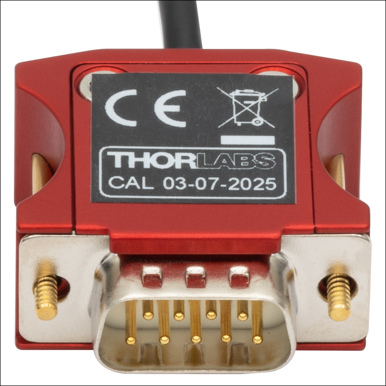
Click to Enlarge
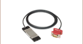
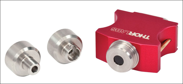
Figure 1.1 Thorlabs' C-Series Power Meter Sensor Connectors Include the Sensor Calibration Data
Connectivity
The sensor connector, shown in Figure 1.1, enables "hot swappable" quick sensor exchange. The sensor connector contains all the sensor information, including NIST-traceable responsivity curves, sensor types, and model number.
The device includes 8 GB of eMMC flash memory for saving data in stand-alone operation, giving the user large memory storage when recording data in the field or away from a computer in the lab. The data can be transferred from the device's internal memory to a PC through a USB 2.0 connection using the USB Type-C connector. Data can also be recorded via the USB PC connection using the Optical Parameter Monitor (OPM) Software. This software is capable of handling up to eight consoles simultaneously. The features of the software are highlighted in the Software tab. Additionally, the OPM Mobile App is available for download for Android™ or iOS® devices (not included), for wireless operation from a mobile device (Item # PM100D3 only, as the OPM Mobile App requires a Bluetooth connection).
In addition to remote control operation and data logging/recording, the USB Type-C connector also acts as the charging system for the Li-Polymer battery using the provided USB Type-C to Type-A cable and any USB charger, such as our DS5 power supply, or computer USB port. The PM100D3 console's wireless charging coil can be used with any compatible wireless charging transmitter rated at 5 W with up to 1 A (not included with purchase).
Recalibration Services
Recalibration services are available for our thermal and photodiode power sensors, pyroelectric energy sensors, and power meter consoles, which we recommend be recalibrated annually for accurate measurements. We recommend your Thorlabs sensor and console be recalibrated as a pair; however, each may be recalibrated individually. All of the sensors on this page come with a manufacturer calibration by default, but we also offer an ISO 17025 accredited calibration for some items. For more information on calibration options, please see the Recalibration tab or the calibration sections at the bottom of this page. For information on recalibration services for our thermal position and power sensors, please contact Tech Support.
*Bluetooth is a registered trademark of Bluetooth Sig, Inc.
| Table 2.1 General Specificationsa | ||
|---|---|---|
| Item # | PM100D2 | PM100D3 |
| Display | ||
| Display Type | 3.5" IPS 640 x 480 px (Full Color) | |
| Display Screens | Numerical with Bar Graph, Line Graph, Statistics, Simulated Analog Needle | Numerical with Bar Graph, Line Graph, Statistics, Simulated Analog Needle, Pass/Fail, Scope |
| Viewing Area | 71.0 mm x 53.3 mm | |
| Refresh Rate | 50 Hz | |
| Audio | Piezoelectric Speaker | |
| Sensor Interface | ||
| Compatible Sensors | Thermal and Photodiode Power Sensors, Pyroelectric Energy Sensors (See Table 2.2 for Sensor Specs) |
Thermal and Photodiode Power Sensors, Thermal Position & Power Sensors, Pyroelectric Energy Sensors, (See Table 2.2 and 2.3 for Sensor Specs) |
| AD Converter | 16-bit | |
| Sampling Speed | 1 kS/s | 1 kS/s, 100 kS/s in Burst and Scope Modes |
| Trigger | Adjustable, 3 - 90% of Each Measurement Range for Pyro and Photodiode in Peak Mode | Adjustable, 3 - 90% of Each Measurement Range for Pyro and Photodiode in Peak Mode, or External Trigger |
| Connector | DB9F, Left Side | |
| Sensor Temperature Control | NTC Thermistor | |
| Temperature Range | -10 to 80 °C | |
| Analog Outputs | ||
| Signal | Amplified Input Signal or 12-bit DAC Corrected Input Signal | Amplified Input Signal, 12-bit DAC Corrected Input Signal, or 14-bit DAC Corrected X-Y Position |
| Voltage Range | 0 to 2.5 V | 0 to 2.5 V (Power), -2.0 to 2.0 V (Position) |
| Accuracy | ±3% | |
| Bandwidth | Up to 100 kHz, Dependent on Sensor and Settings | |
| Connector | SMA - Left Side | SMA - Left Side, AUX Connector - Rear |
| AUX Input/Output | ||
| Function | N/A | 4 GPIO, AN OUT for Power (Analog Input Signal and 12-bit DAC) and Position Sensor (14-bit DAC), I2C, UART, and Analog and Digital Supply Voltages |
| Interfaces and Accessible Memory | ||
| Data Storage | 8 GB eMMC (Accessible via USB) | |
| Interfaces | USB 2.0 Full Speed | USB 2.0 Full Speed / Bluetooth Low Energy / UART |
| Connector | USB-C - Left Side | USB-C - Left Side, AUX Connector - Rear |
| Power Management | ||
| Battery | Li-Polymer, 3.7 V, 2300 mAh | |
| Charger/DC-Input | 5 V / 1 A (USB-C) | 5 V / 1 A (USB-C or Wireless Charging) |
| Dimensions and Mounting | ||
| Dimensions (L x W x H) | 163.0 mm x 98.4 mm x 35.0 mm (6.42" x 3.87" x 1.38") | |
| Weight | 0.355 kg (0.783 lbs) | |
| Mounting Options | Fold-Out Stand, 1/4"-20 Thread | |
| Operating Temperature | 0 to 40 °C | |
| Storage Temperature | -40 to 70 °C | |
Power and Energy Sensor Compatibility Specs
| Table 2.2 Power and Energy Sensor Compatibility Specifications | |||
|---|---|---|---|
| Item # | PM100D2 and PM100D3 | ||
| Detector Compatibility | Photodiode Sensors: S1xxC Series or NS170C Sensor Photodiodes (Max 10 mA) |
Thermal Sensors: S3xxC, S4xxC Series, or S175C Sensor Thermopiles (Max 1 V) |
Pyroelectric Sensors: ESxxxC Series Pyros (Max 200 V) |
| Measurement Ranges | 21 Current Ranges: 2 nA - 10 mA, Ranges Selectable in W or A |
9 Voltage Ranges: 2 mV - 1 V, Ranges Selectable in W or V |
13 Voltage Ranges: 20 mV - 200 V, Ranges Selectable in J or V |
| Wavelength Ranges | 200 nm - 5.5 µm (Sensor Dependent) | 190 nm - 20 μm (Sensor Dependent) | 185 nm - 25 μm (Sensor Dependent) |
| Power / Energy Ranges | 100 pW - 20 W (Sensor Dependent) | 10 μW - 200 W (Sensor Dependent) | 10 μJ - 15 J (Sensor Dependent) |
| Accuracy | ±0.2% of Full Scale (>400 nA - 10 mA) ±0.5% of Full Scale (2 nA - 400 nA) |
±0.5% of Full Scale (>4 mV - 1 V) ±1% of Full Scale (2 mV - 4 mV) |
±0.5% of Full Scale (20 mV - 200 V) |
| Display Resolution | 1 pA / Responsivity Value (A/W) | 1 µV / Responsivity Value (V/W) | 10 µV / Responsivity Value (V/J) |
| Bandwidth | DC - 100 kHz, Dependent on Sensor and Settings | DC - 10 Hz, Dependent on Sensor and Settings | - |
| Max Repetition Rate | N/A | N/A | 50 kHz |
| Table 2.3 Thermal Position and Power Sensor Compatibility Specifications | |||
|---|---|---|---|
| Item # | PM100D3 Only | ||
| Detector Compatibility | Thermal Position and Power Sensors: S44xC Series | ||
| Measurement Ranges | 9 Voltage Ranges: 2 mV - 1 V | ||
| Wavelength Range | 190 nm - 20 µm | ||
| Power Ranges | 0.5 mW - 50 W (Sensor Dependent) | ||
| Position Accuracy | As Low as 50 µm (Sensor Dependent) | ||
| Digital Position Resolution | 1 µm | ||
For a full list of the sensor head specifications please visit the Photodiode Power Sensors, Thermal Power Sensors, Pyroelectric Energy Sensors, or Calibrated Thermal Position and Power Sensors pages. For other information, please contact Tech Support.
Figure 3.1 PM100Dx Sensor Connector9-Pin D-Sub Female
|
||||||||||||||||||||||
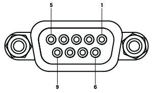
Figure 3.3 PM100D3 Console Only: AUX Connector26-Pin Female
|
||||||||||||||||||||||||||||||||||
Interactive Demo
An interactive GUI is available in this tab to demo all the features of the front panel of the PM100Dx power and energy meter consoles. A full-screen demo is also available by clicking the button to the right. For computers with a touchscreen, the demo supports all swipe gestures to switch screens. Otherwise, a mouse can be used to interact with these functions. The arrow and enter key on a keyboard can be used to simulate the arrow and OK keys on the device, but the menu and delta keys on the demo function as on the device. The GUI provides the opportunity to browse all submenus, change settings, and perform simulated measurements.
For information on navigating the menus, please see the PM100Dx manual, or, in the GUI, click on the three lines in the top left of the touchscreen, and then select Tips.
The demo GUI simulates the operation of either the PM100D2 or PM100D3 console with the S120C photodiode power sensor or the S405C thermal power sensor head connected to the device.
PM100D2 and PM100D3 Front and Back Panels and Recessed Connector Plane
Click to Enlarge
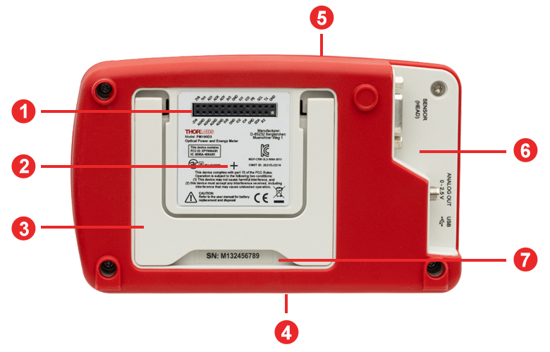
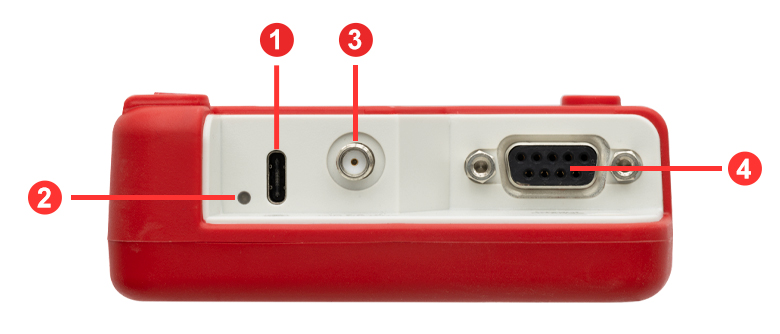
Figure 5.2 PM100Dx Power Meter Back Panel (PM100D3 Console Shown)
Click to Enlarge
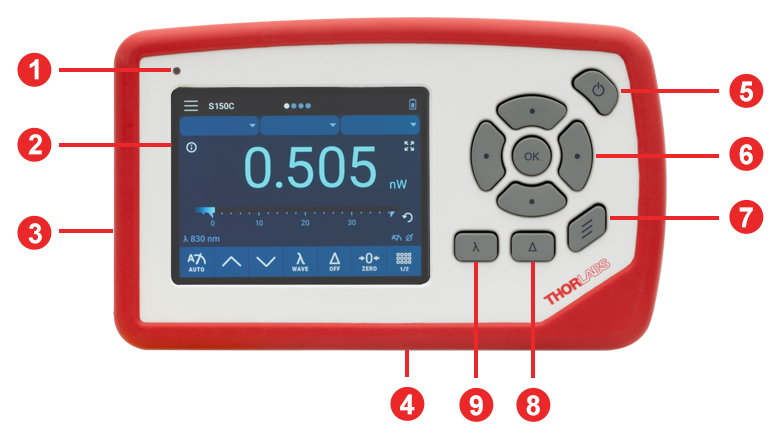
Figure 5.1 PM100Dx Power Meter Front Panel
| Back Panel | |
|---|---|
| Callout | Description |
| 1 | PM100D3 Console Only: AUX Connector (See Figure 3.3 and Table 3.4 in the Pin Diagrams tab) |
| 2 | PM100D3 Console Only: Inductive Charging Coil Center Marking |
| 3 | Fold-Out Stand |
| 4 | 1/4"-20 Post Mounting Thread in the Vertical Bottom Face |
| 5 | PM100D3 Console Only: Bluetooth Antenna |
| 6 | Recessed Connector Plane with Sensor, Analog Out, and USB Interface (See Figure 5.3) |
| 7 | Device Serial Number |
| Front Panel | |
|---|---|
| Callout | Description |
| 1 | Ambient Light Sensor |
| 2 | Touch Screen Display |
| 3 | Recessed Connector Plane (See Figure 5.3) |
| 4 | 1/4"-20 Post Mounting Thread in the Vertical Bottom Face |
| 5 | Power On/Off Button |
| 6 | Control Pad for Navigation (Up, Down, Left, Right) and Enter (OK) Keys |
| 7 | Menu Button |
| 8 | Delta Button for Relative Measurements |
| 9 | Lambda Button for Spectral Correction |
Click to Enlarge
Figure 5.3 PM100Dx Power Meter Left Side Recessed Connector Plane
| Connector Plane | |
|---|---|
| Callout | Description |
| 1 | USB Type-C Connector for Charging and Remote Operation |
| 2 | Charging Indicator |
| 3 | Analog Output SMA Connector |
| 4 | Sensor D-Sub 9-Pin Female Connector (See Figure 3.1 and Table 3.2 in the Pin Diagrams tab) |
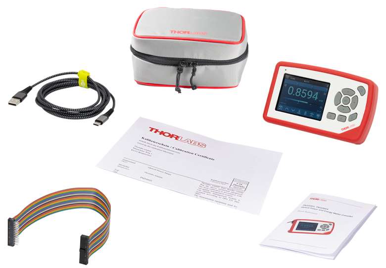
Each PM100Dx Device is Shipped with the Following:
- PM100D2 or PM100D3 Optical Power and Energy Meter Console
- USB Cable, Type-A to Type-C, 2 m Long
- Certificate of Calibration
- Quick Reference
- PM100D3 Console Only:
- AUX Connector Extension Cable, 300 mm Long
- Softshell Storage Bag for Console and Sensors
Click to Enlarge
Figure 6.1 Items Shipped With Each PM100Dx Console (AUX Connector Extension Cable and Softshell Storage Bag Shipped with PM100D3 Console Only)
Compatible Power Meters
- Consoles:
- PM100A Analog Power and Energy Meter Console
- PM200 Legacy Touch Screen Power and Energy Meter Console
- PM100D Legacy Digital Power and Energy Meter Console
- PM100D2 and PM100D3 Digital Power and Energy Meter Consoles (Version 7.0)
- PM400 Capacitive Touchscreen Power and Energy Meter Console
- PM5020 Dual-Channel Benchtop Optical Power and Energy Meter Console (Version 4.0 or Later)
- Complete Power Meters:
- PM160, PM160T, and PM160T-HP Wireless Handheld Power Meters with Bluetooth® Technology
- PM16 Series Compact USB Power Meters
- PM60 and PM61 Fiber Optic Power Meter Series (Version 6.0 or Later)
- Interfaces:
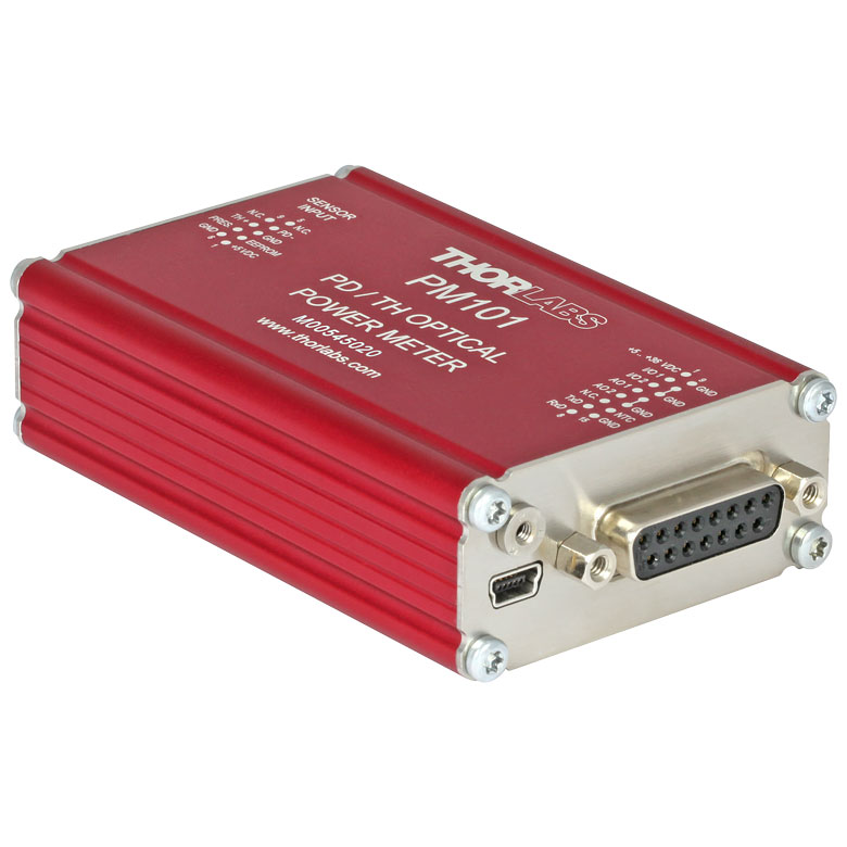
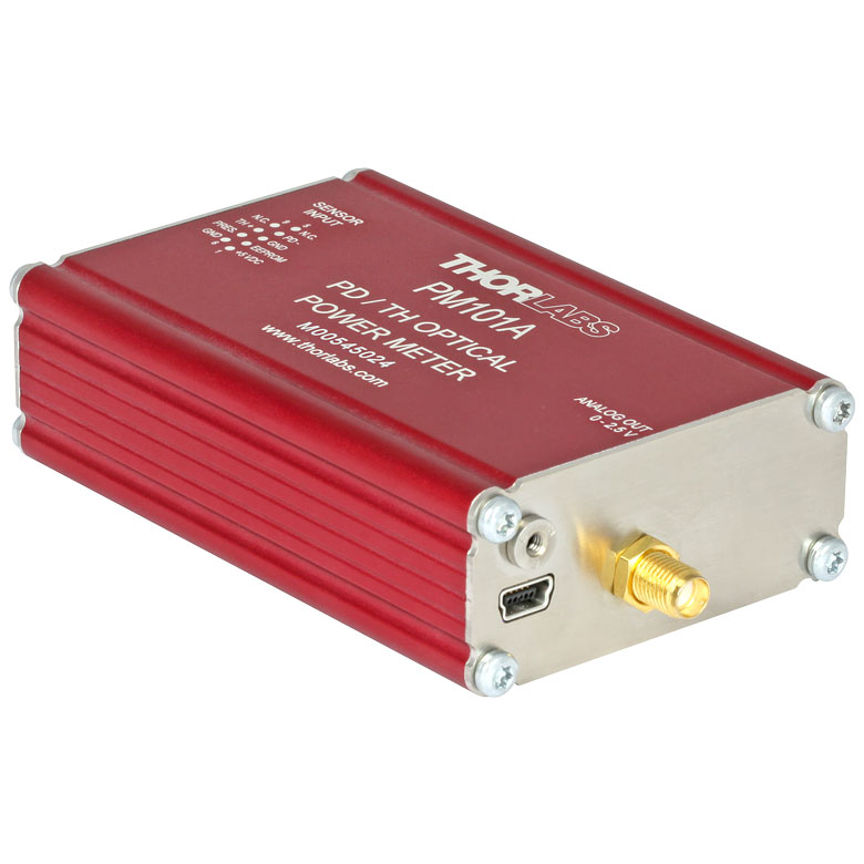
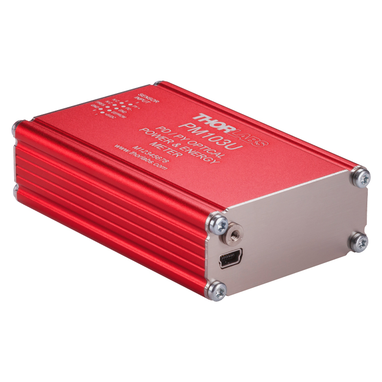
- PM101 Series Power Meter Interfaces with External Readout (Version 2.0 or Later)
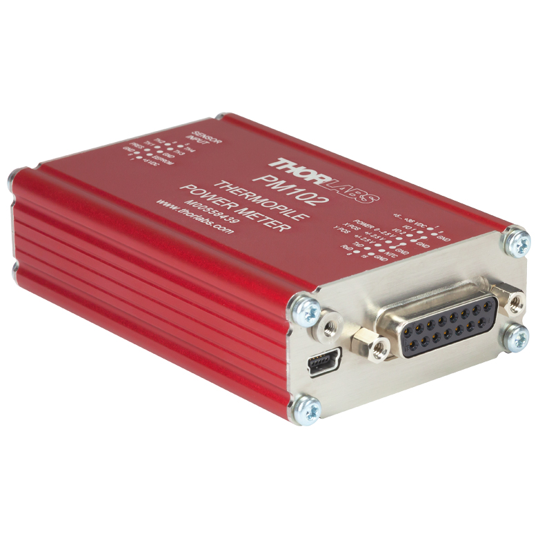
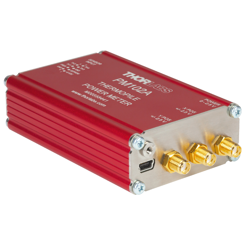
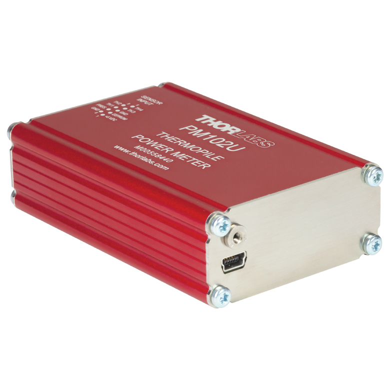
- PM102 Series Power Meter Interfaces with External Readout (Version 2.1 or Later)
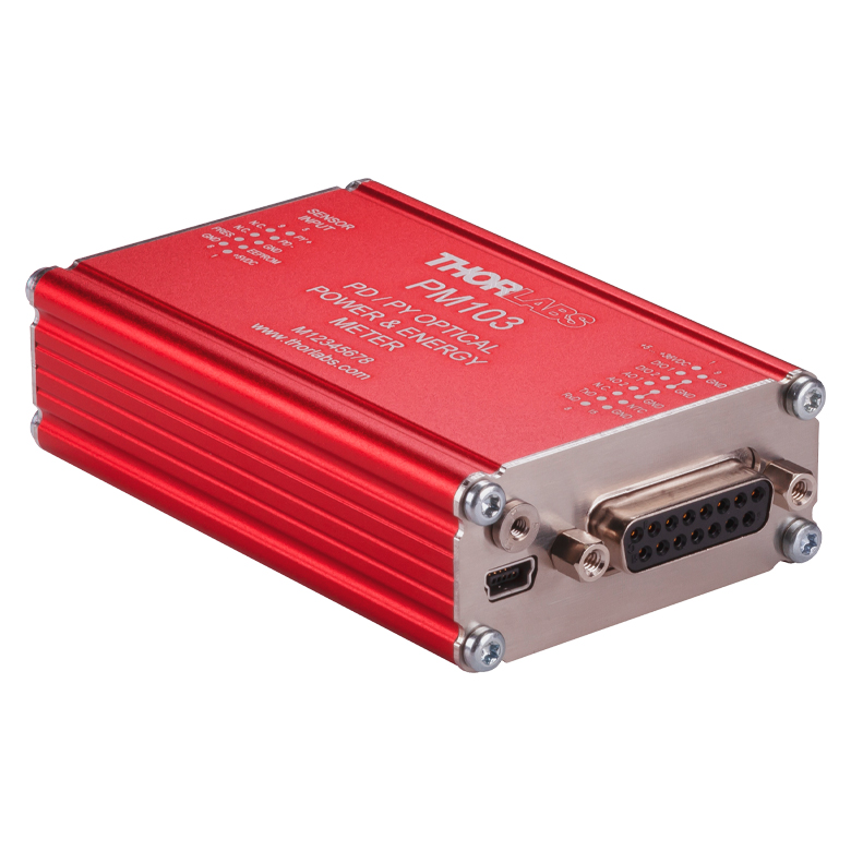
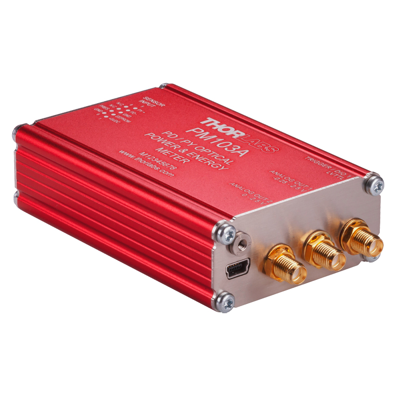
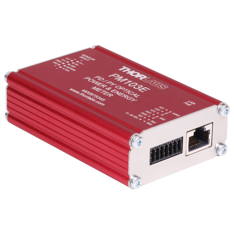
- PM103 Series Power Meter Interfaces with External Readout (Version 3.0 or Later)
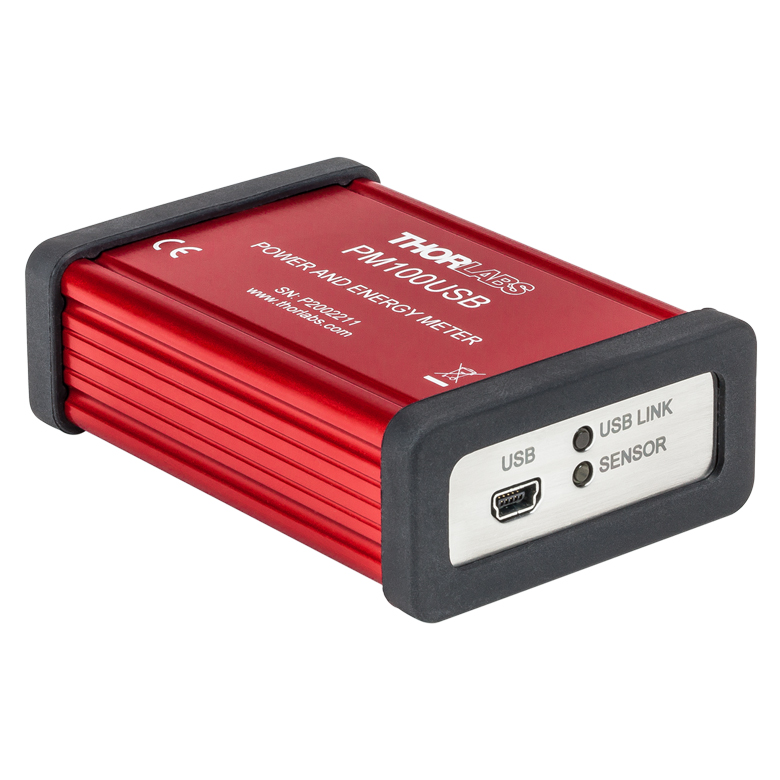
- PM100USB USB Interface Digital Power and Energy Meter
Other Compatible Devices
- ERM2xx Series Extinction Ratio Meters
- SPCNT Single Photon Counting Device
- TSP01 USB Temperature and Humidity Data Logger
- TSP-TH Additional Temperature Probe
- WM202 Wavelength Meter
Optical Parameter Monitor
The Optical Parameter Monitor GUI software features readout from up to eight power meters or other compatible devices, or remote wireless operation.
For details on specific software features, please see the user manual.
Users interested in the legacy Power Meter Software can find it by visiting the software page.
The PM100D2 and PM100D2 are only compatible with version 7.0. The PM101 Series Power Meters are only compatible with version 2.0 or later. The PM102 Series Power Meters are only compatible with version 2.1 or later. The PM103 Series Power and Energy Meters are only compatible with version 3.0 or later. The PM5020 Console is only compatible with version 4.0 or later. The PM60 and PM61 Power Meter Series are only compatible with version 6.0 or later.
Optical Parameter Monitor GUI Software for Touchscreen, Handheld, and USB-Interface Power Meters
Features
- Operate up to Eight Devices Simultaneously
- Record and Analyze Measurements in Real Time
- Intuitive Analog Display and Graphing Modes
- Configurable Long-Term Data Logging
- Also Supports Position Measurements with Thermal Position & Power Sensors
- Compatible with USB, Bluetooth®, Ethernet, and Serial Connections
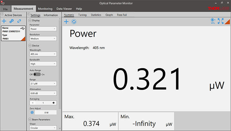
The Optical Parameter Monitor (OPM) software GUI enables seamless control of up to eight compatible devices that are connected via USB, RS232, Ethernet, or Bluetooth®,a wireless technologyb. The latest software, firmware, drivers, and utilities for these power meters can be downloaded here.
Multiple data measurement and analysis functions are integrated into the GUI package. The interface offers a user-friendly design with minimal use of color and low brightness that is ideal for use in dark lab environments while wearing laser safety glasses. Measured data can be displayed in real time as a simulated analog needle, digital value, line graph, or bar graph. Continuously logged and short-term measurements can be recorded for data viewing and analysis at a later point. A built-in statistics mode analyzes measured data and updates continuously to reflect new measurements within the pre-determined measurement period. Beam position measurements are also supported when used with our thermal position and power sensors and a compatible power meter.
The OPM software package installs the GUI, which then can be used to control the touchscreen, handheld, or USB-interface power meters and other compatible devices. Firmware updates for supported devices are also available. Programming examples and drivers for interfacing with our power and energy meter consoles using LabVIEW, C/C++, Visual C#, and Python are installed with the software.
Please note that the OPM Software uses different drivers than the Power Meter Utilities Software and Thorlabs recommends using the new driver TLPM.dll. For users who wish to use the legacy Power Meter Software or use custom software designed using the older PM100D.dll driver, a Power Meter Driver Switcher program is included for easy swapping of the installed driver between the two versions.
- Bluetooth is a registered trademark of Bluetooth Sig, Inc.
- The PM100D3, PM61 Series, PM160, PM160T, and PM160T-HP power meters are equipped with Bluetooth connections.
Click to Enlarge
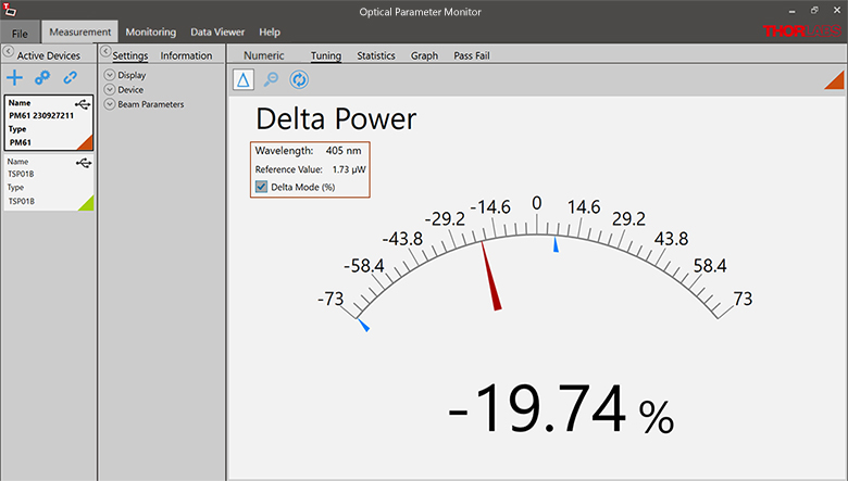
Figure 149B Tuning Mode
Simulated analog needle and digital measurement value provided. Delta Mode, enabled here, shows the fluctuation range during the measurement period.
Click to Enlarge
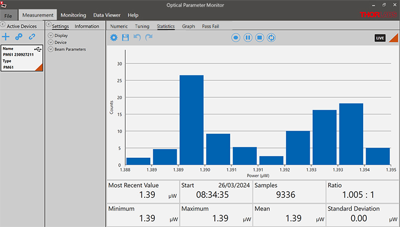
Figure 149C Statistics Mode
Calculate numerical statistics for a pre-determined measurement period. The panel displays the analyzed values in a bar graph and the results as numerical values.
Click to Enlarge
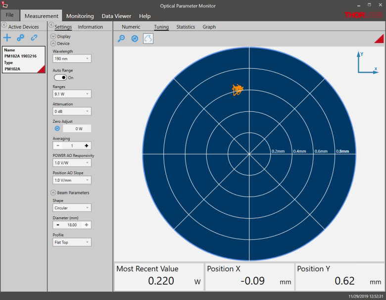
Figure 149D Position Tuning Mode
Tuning mode can be used with a thermal position and power sensor to aid in beam alignment, if the connected power meter supports it.
Click to Enlarge
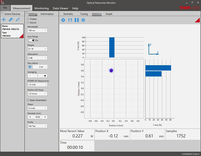
Figure 149E Position Statistics Mode
Statistics mode also provides aggregate information for thermal position and power sensors, if they are supported.
Click to Enlarge
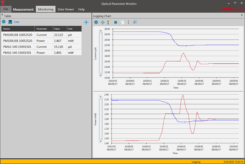
Figure 149F Monitoring Mode
Enable long-term measurement and simultaneous recording from up to eight power meters. Save data as .csv files for later processing while measurement results are displayed in a graph in real time.
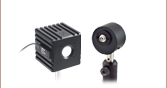
Standard Photodiode Sensor Mounting Options
Click to Expand
Figure 818B S120C and S120-SMA Fiber Adapter
Click to Expand
Figure 818A S120C and S120-FC Fiber Adapter
The compact design of Thorlabs' Standard Photodiode Sensors allows easy integration into existing setups. Typical mounting configurations including post, cage, and lens tube options are available. Shown on this page are several different choices for mounting these sensors.
The standard photodiode sensors are compatible with all S120-xx series fiber adapters. FC/PC and SMA adapters are shown in Figures 818A and 818B. Adapters for FC/APC, SC, LC, and ST connections are also available.
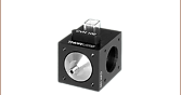
Click to Expand
Figure 818D S120C and Flip Mount
Click to Expand
Figure 818C S120C and Flip Mount
Flip mounts are convenient for quick power measurements from a static location. The sensor can be placed in the path of the laser beam for the power measurement and flipped down during normal operation of the system.
FM90(/M) Right-Angle Flip Mounts are shown in Figures 818C and 818D. Thorlabs also offers the TRB1(/M) Articulating Post Mount. The lockable articulating mount offers adjustable positioning of the sensor head.
Click to Expand
Figure 818F S120C and QRC1A
Click to Expand
Figure 818E S120C and KB1P
The standard photodiode sensors also feature externally SM1-threaded connections on the front face. The SM1 threading provides easy mounting to 1" lens tube systems and quick-release mounts.
Shown in Figures 818E and 818F are the KB1P(/M)
Note: Due to the thickness of the S12xC sensor, the QRC1A and CP44F (shown below) quick-release mounts can only be fully removed from the cage system by backing them off an open end. The two mounts are easily removed from the cage system if only three cage rods are used; see Figure 818F.
Click to Expand
Figure 818G S120C and CP44F
Thorlabs also offers the CP44F 30 mm Cage Plates with Quick-Release Mounts. These mounts feature magnetically coupled front and back plates for easy and repeatable mounting.
Note: Like the QRC1A, the CP44F cannot be removed from a closed cage system.
Slim Photodiode Sensor Mounting Options
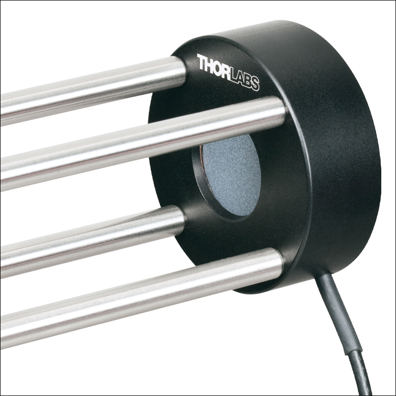
Click to Expand
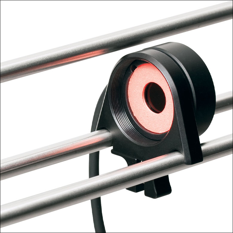
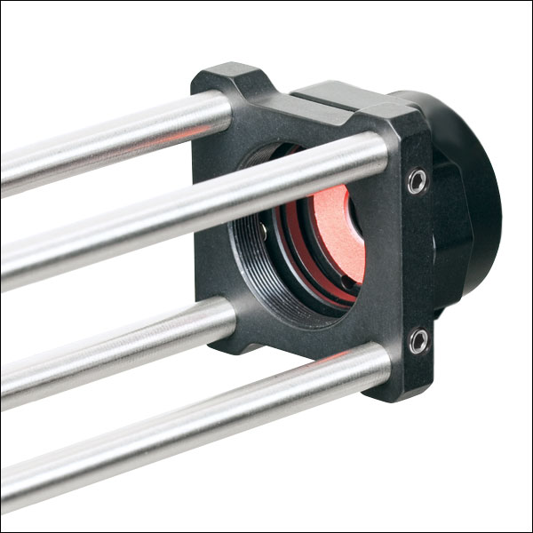
Figure 818H S130C Sensor in a 30 mm Cage
Thorlabs' Slim Photodiode Sensors are designed to fit into space-restricted environments such as 30 mm cage systems and optic-dense free-space arrangements.
Shown in Figure 818H is a S130C Sensor inserted into a 30 mm cage system. The application shown highlights the ease with which the sensor can be inserted into the cage, and the minimal space needed to take a power measurement.
The slim photodiode sensors may also be mounted on a TRB1(/M) Articulating Mount. This mount allows repeatable insertion of the sensor into tight optic arrangements. After the measurement is made, the sensor may be rotated out of the beam path for normal operation.
Compact Slim Photodiode Sensor Mounting Options
Click to Expand
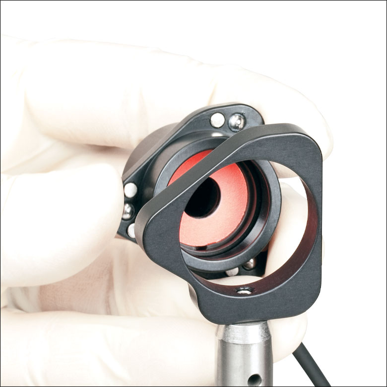
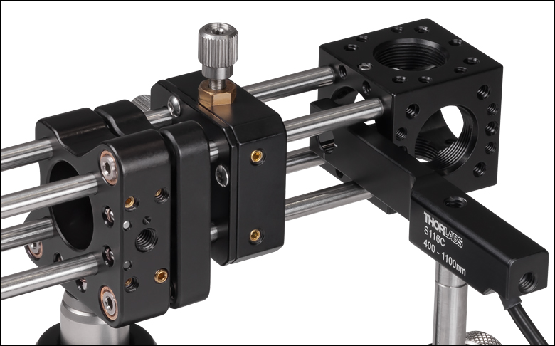
Figure 818I S116C Sensor in a 16 mm Cage
Thorlabs' Compact Slim Photodiode Sensors are designed to fit into even tighter spaces such as 16 mm cage systems, our slotted Ø1/2" lens tubes, and other optic-dense free-space arrangements.
Shown in Figure 818I is a S116C Sensor inserted into a 16 mm cage system. The application shown highlights the ease with which the sensor can be inserted into the cage, and the minimal space needed to take a power measurement.
The compact slim photodiode sensor has two 8-32 (M4) taps for post mounting. One tap mounts the sensor horizontally, as seen in Figure 818I, and one allows it to be mounted vertically. The sensor may also be mounted on a TRB1(/M) Articulating Mount. This mount allows repeatable insertion of the sensor into tight optic arrangements. After the measurement is made, the sensor may be rotated out of the beam path for normal operation.
Microscope Slide Photodiode Sensor Mounting Options
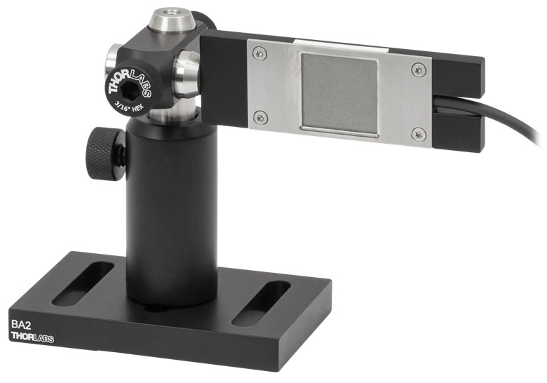
S170C Mounted on a Post
Figure 818K The S170C may be post mounted via the 8-32 (M4 x 0.7) tap in the side of the housing.

Click to Expand
Figure 818J S170C in a Microscope Slide Holder
Thorlabs' Microscope Slide Power Sensors are designed so they can be mounted directly in a microscope slide holder. The 76.0 mm x 25.2 mm x 5.0 mm sensor head has the same footprint as a standard microscope slide and is compatible with most standard upright and inverted microscopes. Figure 818J shows the S170C power sensor flipped over so that the engraved back of the housing can be used for alignment.
The S170C and NS170C power sensors also have an 8-32 (M4 x 0.7) tap for post mounting. In Figure 818K, an RA90(/M) Right-Angle Clamp is used with two Ø1/2" posts to mount the S170C sensor head in a horizontal orientation.
Integrating Sphere Photodiode Sensor Mounting Options
Click to Expand
Figure 818M S140C and S140-BFA Fiber Adapter
Click to Expand
Figure 818L S140C and S120-FC Fiber Adapter
Thorlabs' Integrating Sphere Photodiode Sensors provide a low-loss cavity for diverging, non-uniform, or off-axis beam measurements. These integrating spheres are ideal for all fiber-based applications due to the beam divergence at the end of the fiber.
Shown in Figure 818L is an S140C Integrating Sphere with an S120-FC Fiber Adapter and shown in Figure 818M is an S140C with an S140-BFA Bare Fiber Adapter. The bare fiber adapter features a mounting clamp and light shield to decrease interference from ambient light.
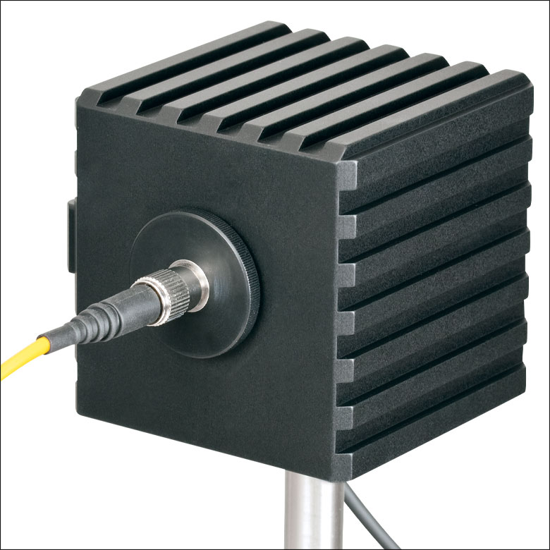
Compact Fiber Photodiode Sensor Mounting Options
Click to Expand
Figure 818O PM100D2 with S150C Sensor
Click to Expand
Figure 818N S150C Sensor with FC and SMA Connectors
Thorlabs' Compact Fiber Photodiodes are the ideal choice for a portable, fiber-coupled power meter. The S15xC sensors are compatible with a wide variety of fiber connections. PM20-xx adapters are available to couple FC, APC, SMA, ST, SC, and LC connectors with the sensors. Shown in Figure 818N is an S150C Sensor with FC and SMA connector adapters.
Shown in Figure 818O is a PM100D2 console with an S150C sensor connected to an FC connectorized optical fiber. This setup is ideal for portable use in the lab or in the field.
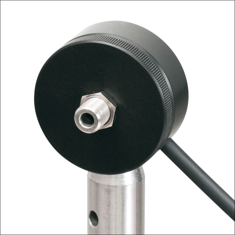
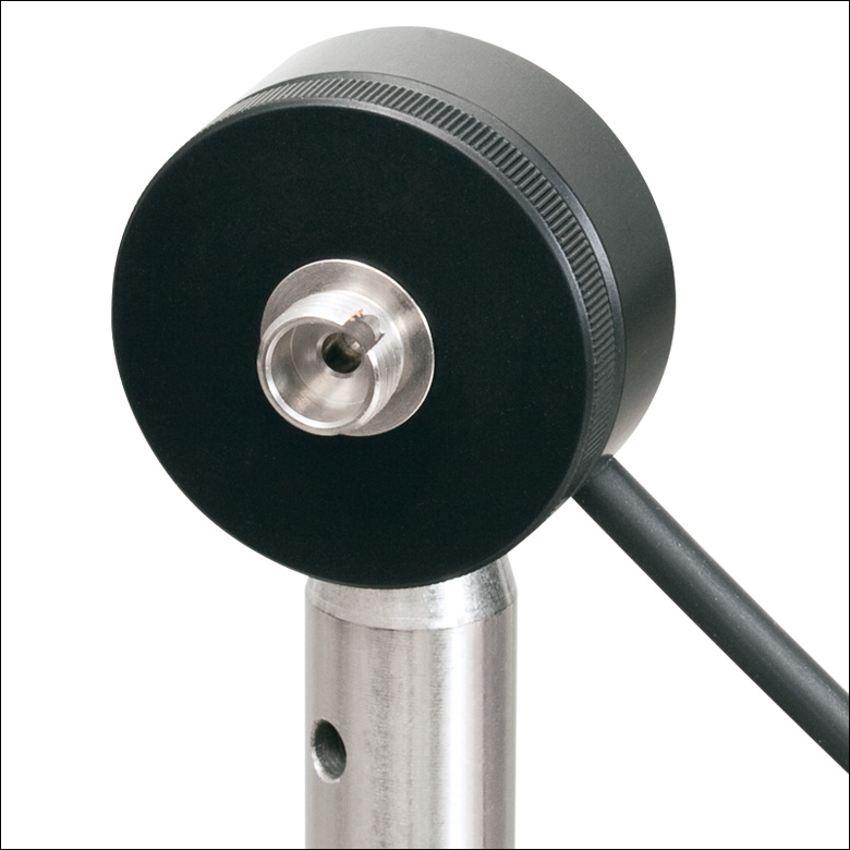
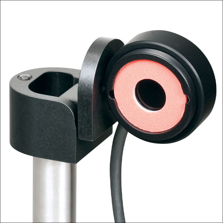
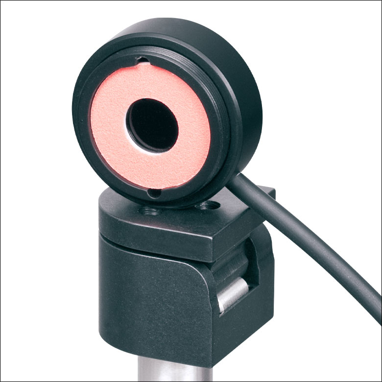
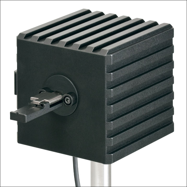
Pyroelectric Energy Sensor Mounting Options
Click to Expand
Figure 818P ES220C Mounted on 30 mm Cage Rods
Thorlabs' Pyroelectric Energy Sensors are ideal for measuring pulsed sources. These pyroelectric sensors provide direct energy readings for those sources. The sensors are designed to handle medium- to high-energy pulses from excimer, YAG, and other high-power lasers.
Each sensor ships with an insulating adapter for Ø1/2" post mounting, and they are also compatible with our 30 mm cage system, as shown in Figure 818P.
Click to Enlarge
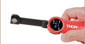
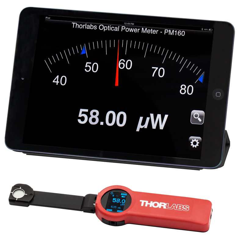
Figure 113A The PM160 wireless power meter, shown here with an iPad mini (not included), can be remotely operated using Apple mobile devices.
This tab outlines the full selection of Thorlabs' power and energy sensors. Refer to Table 113B for power meter console and interface compatibility information.
In addition to the power and energy sensors listed below, Thorlabs also offers all-in-one, wireless, handheld power meters and compact USB power meter interfaces that contain either a photodiode or a thermal sensor, as well as power meter bundles that include a console, sensor head, and post mounting accessories.
Thorlabs offers four types of sensors:
- Photodiode Sensors: These sensors are designed for power measurements of monochromatic or near-monochromatic sources, as they have a wavelength dependent responsivity. These sensors deliver a current that depends on the input optical power and the wavelength. The current is fed into a transimpedance amplifier, which outputs a voltage proportional to the input current.
- Thermal Sensors: Constructed from material with a relatively flat response function across a wide range of wavelengths, these thermopile sensors are suitable for power measurements of broadband sources such as LEDs and SLDs. Thermal sensors deliver a voltage proportional to the input optical power.
- Thermal Position & Power Sensors: These sensors incorporate four thermopiles arranged as quadrants of a square. By comparing the voltage output from each quadrant, the unit calculates the beam's position.
- Pyroelectric Energy Sensors: Our pyroelectric sensors produce an output voltage through the pyroelectric effect and are suitable for measuring pulsed sources, with a repetition rate limited by the time constant of the detector. These sensors will output a peak voltage proportional to the incident pulse energy.
| Table 113B Console Compatibility | |||||||||
|---|---|---|---|---|---|---|---|---|---|
| Console Item # | PM100A | PM100D2 | PM100D3 | PM400 | PM5020 | PM101 Series |
PM102 Series |
PM103 Series |
PM100USB |
| Photodiode Power | |
|
|
|
|
|
- | |
|
| Thermal Power | |
|
|
|
|
|
|
- | |
| Thermal Position | - | - | |
|
|
- | |
- | - |
| Pyroelectric Energy | - | |
|
a |
|
- | - | |
a |
Power and Energy Sensor Selection Guide
There are two options for comparing the specifications of our Power and Energy Sensors. Tables 113C, 113D, 113E, and 113F sort our sensors by type (e.g., photodiode, thermal, or pyroelectric) and provide key specifications.
Alternatively, the selection guide Figures 113G and 113H arrange our entire selection of photodiode and thermal power sensors by wavelength (Figure 113G) or optical power range (Figure 113H). Each box contains the item # and specified range of the sensor. These graphs allow for easy identification of the sensor heads available for a specific wavelength or power range.
| Table 113C Photodiode Power Sensors |
|---|


| Table 113D Thermal Power Sensors |
|---|


| Table 113E Thermal Position & Power Sensors |
|---|

| Table 113F Pyroelectric Energy Sensors |
|---|


 Figure 113G Sensor Options Arranged by Wavelength Range
 Figure 113H Sensor Options Arranged by Power Range
Figure 796A DAkkS-accredited calibrations are performed in accordance with DIN EN ISO/IEC 17025:2018.
Recalibration Services
Thorlabs offers two types of recalibration services in-house for our power and energy meter electronics and photodiode power sensors: ISO 17025 accredited calibrations and manufacturer calibrations. Only the manufacturer calibration is available for the NS170C microscope slide peak power sensor, our thermal power sensors, and our pyroelectric energy sensors. All new products are delivered with a manufacturer calibration by default; if an ISO 17025 accredited calibration is desired for a new device, please contact Tech Sales.
ISO 17025 accredited calibrations are performed in-house in accordance with DIN EN ISO/IEC 17025:2018. Thorlabs GmbH's calibration laboratory is accredited by the German Accreditation Body (DAkkS), the national accreditation authority of the Federal Republic of Germany. The scope of services is described here in English or German. Accredited calibrated power and/or energy meter electronics come with a dedicated certificate of calibration proving the specified accuracy and traceability of calibration data. This certification may be required in certain applications or industries, such as the medical market.
In contrast, our manufacturer calibrations are subject to the quality management requirements of ISO 9001. The certificate of calibration lists the equipment used for the calibration procedure as well as the calibration data acquired. The manufacturer calibration of a power sensor includes recalibration of a single-channel console or interface at no additional cost. If you wish to calibrate one or more sensors with a dual-channel console, each sensor and console calibration service will need to be purchased individually.
Both types of calibration can be offered for third-party equipment or adjusted for special requirements upon request. Please reach out to Tech Sales for further details.
We recommend recalibrating your Thorlabs sensor and console as a pair; however, each may be recalibrated individually. To ensure accurate measurements, we recommend recalibrating annually. To order one or more sensor recalibrations with a dual-channel console, we offer two options: either 1) fill out the Returns Material Authorization (RMA) form with each console and sensor Item # to be recalibrated and specify either manufacturer calibration or ISO 17025 accredited calibration in the "Further Details" field, or 2) separately add each recalibration service Item # offered below to your cart.
Thorlabs offers a wide selection of power and energy meter consoles and interfaces for operating our power and energy sensors. Key specifications of all of our power meter consoles and interfaces are presented in this tab to help you decide which device is best for your application. We also offer self-contained wireless power meters and compact USB power meters.
When used with our C-series sensors, Thorlabs' power meter consoles and interfaces recognize the type of connected sensor and measure the current or voltage as appropriate. Our C-series sensors have responsivity calibration data stored in their connectors. The console will read out the responsivity value for the user-entered wavelength and calculate a power or energy reading.
- Photodiode sensors deliver a current that depends on the input optical power and the wavelength. The current is fed into a transimpedance amplifier, which outputs a voltage proportional to the input current. The photodiode's responsivity is wavelength dependent, so the correct wavelength must be entered into the console for an accurate power reading. The console reads out the responsivity for this wavelength from the connected sensor and calculates the optical power from the measured photocurrent.
- Thermal sensors deliver a voltage proportional to the input optical power. Based on the measured sensor output voltage and the sensor's responsivity, the console will calculate the incident optical power.
- Thermal position and energy sensors incorporate four thermopiles arranged as quadrants of a square. By comparing the voltage output from each quadrant, the unit calculates the beam's position.
- Energy sensors are based on the pyroelectric effect. They deliver a voltage peak proportional to the pulse energy. If an energy sensor is recognized, the console will use a peak voltage detector, and the pulse energy will be calculated from the sensor's responsivity.
The consoles and interfaces are also capable of providing a readout of the current or voltage delivered by the sensor. Select models also feature an analog output.
Consoles
| Item # | PM100A | PM100D2 | PM100D3 | PM400 | PM5020 |
|---|---|---|---|---|---|
| (Click Photo to Enlarge) | 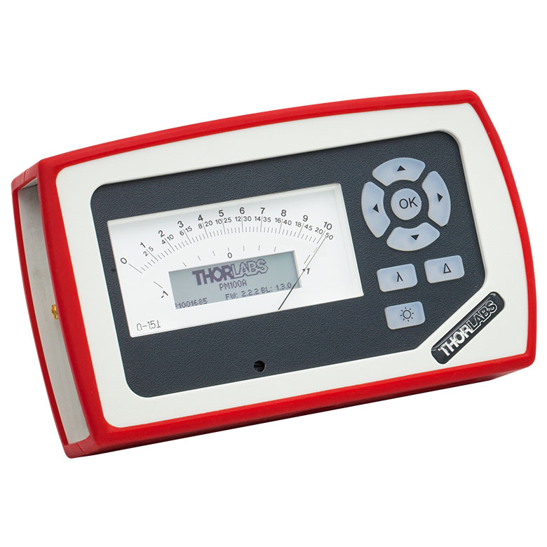 |
 |
 |
 |
 |
| Sensor Compatibility (Sensors Not Included) | |||||
| Photodiode Power | |
|
|
|
|
| Thermal Power | |
|
|
|
|
| Thermal Position & Power | - | - | |
|
|
| Pyroelectric Energy | - | |
|
a |
|
| Key Features | |||||
| Housing Dimensions (H x W x D) |
7.24" x 4.29" x 1.61" (184 mm x 109 mm x 41 mm) |
6.42" x 3.87" x 1.38" (163.0 mm x 98.4 mm x 35.0 mm) |
5.35" x 3.78" x 1.16" (136.0 mm x 96.0 mm x 29.5 mm) |
9.97" x 4.35" x 11.56" (253.2 mm x 110.6 mm x 293.6 mm) |
|
| Channels | 1 | 2 | |||
| External Temperature Sensor Input (Sensor Not Included) | - | - | Readout and Record Temperature Over Time | ||
| External Humidity Sensor Input (Sensor Not Included) | - | - | Readout and Record Humidity Over Time | ||
| Analog Outputb | Amplified Input Signal, SMA, 0 to 2 V, Up to 100 kHz |
Amplified Input Signal or 12-bit DAC Corrected Input Signal, SMA, 0 to 2.5 V, Up to 100 kHz |
Amplified Input Signal, 12-bit DAC Corrected Input Signal, or 14-bit DAC Corrected X-Y Position Signal, SMA, 0 to 2.5 V (Power); -2.0 to 2.0 V (Position), Up to 100 kHz |
Amplified Input Signal or DAC Corrected Input Signal, 2p Audio 3.5 mm (Adapter to BNC included), 0 to 2 V, Up to 100 kHz |
Amplified Input Signal or DAC Corrected Input Signal, 2 x BNC, -2.5 to 10 V, Up to 250 kHz. Programmable AOc, 4 x BNC, -5 to 10 V, Up to 1 kHz |
| Input/Output Ports | - | 26-Pin AUX Connector With 4 GPIO, AN OUT for Power (Analog Input Signal and 12-bit DAC) and Position Sensor (14-bit DAC), I2C, UART, and Analog and Digital Supply Voltages | 14-Pin AUX Connector With 4 GPIO, Programmable, 2 x 10 bit ADC for External Temperature, Relative Humidity Sensor, +3.3 V, ±2.5 V (100 mA Max) |
10-Pin PCB Connector, 4 Configurable Digital I/O Channels, 1 Trigger In/Out, I2C (LVTTL / TTL) |
|
| Shutter Control | - | - | - | - | Support for SH05R(/M) or SH1(/M) Optical Shutter with Interlock Input |
| Fan Control | - | - | - | - | |
| Source Spectral Correction | - | ||||
| Attenuation Correction | - | ||||
| External Trigger Input | - | - | - | ||
| Display | |||||
| Type | Mechanical Needle and LCD Display with Digital Readout | 3.5" Full Color Touchscreen Display, 640 x 480 Pixels | 4.3" Protected Capacitive Touchscreen with Color Display, 400 x 272 Pixels | 5" IPS Touchscreen LCD Display, 854 x 480 Pixels | |
| Dimensions | Digital: 1.9" x 0.5" (48.2 mm x 13.2 mm) Analog: 3.54" x 1.65" (90.0 mm x 42.0 mm) |
2.80" x 2.10" (71.0 mm x 53.3 mm) |
3.7" x 2.1" (95 mm x 54 mm) |
4.32" x 2.43" (109.7 mm x 61.6 mm) |
|
| Refresh Rate | 20 Hz | 50 Hz | 10 Hz (Numerical) 25 Hz (Analog Simulation) |
25 Hz | |
| Measurement Viewsd | |||||
| Numerical | |||||
| Mechanical Analog Needle | - | - | - | - | |
| Simulated Analog Needle | - | ||||
| Bar Graph | - | ||||
| Trend Graph | - | ||||
| Statistics | |||||
| Pass/Fail | - | - | - | - | |
| Scope | - | - | - | ||
| Memory | |||||
| Type | - | eMMC Flash | NAND Flash | SD Card | |
| Size | - | 8 GB | 4 GB | 8 GB | |
| Power | |||||
| Battery | LiPo 3.7 V 2300 mAh | LiPo 3.7 V 2300 mAh | LiPo 3.7 V 2300 mAh | - | |
| External | 5 VDC via USB or Included AC Adapter | 5 VDC via USB-C Connector | 5 VDC via USB Mini B Connector | Line Voltage: 100 - 240 V | |


| Posted Comments: | |
Evangeline Wolanski
(posted 2025-09-22 14:52:51.907) Could we get a replacement battery for this powermeter, or send it in to be fixed? It won't turn on unless it's been charging for a long time. And when you CAN get it to turn on, only the model title screen turns on for a second or two before turning off again. jjadvani
(posted 2025-09-23 02:38:33.0) Dear Evangeline, thank you for contacting Thorlabs. We can replace the PM100D battery for you. My colleague will contact you directly with details on how to return the item for repair. 晓波 孙
(posted 2025-08-18 18:57:24.55) Hi, I have a PM100D console. When entering into the menu to set 'Left sub display' & 'Right sub display', it seems that the screen does not change to what I had set. hchow
(posted 2025-08-19 04:31:22.0) Dear Mr. Sun, thank you for your feedback. I will personally contact you to assist you with your enquiry. Xing Li
(posted 2025-07-26 01:26:02.49) 您好,我有一台Thorlabs PM100D光功率计。现在发现相关的充电器丢失。能否告知我们如何充电插口的相关尺寸及充电要求?如果能提供电源的采购建议更好。谢谢! jjadvani
(posted 2025-07-28 05:49:35.0) The power supply for the PM100D is a 5V DC output with a barrel outlet connection. My colleague in China will contact you directly to provide more details. yuanfang sun
(posted 2025-07-15 18:39:15.94) Hi, our power meter console PM100D could not write to the statistics file, every time I get the error 0x000000B8 "SD card is write protected", it has been confirmed that the SD card is inserted correctly and the SD card is not corrupted. Could you help with some suggestions to solve the problem? Thanks! hkarpenko
(posted 2025-07-15 10:42:21.0) Dear Yuanfang,
thank you for your feedback. The PM100D console needs a specific format type to work with, thus it is necessary to format the SD card prior to usage. I will contact you directly to discuss this issue in detail with you. Yifan Zhu
(posted 2025-03-31 17:47:51.83) The power supply of our power meter is lost, could you please provide me a quote for the corersponding power supply?
Thanks. cdolbashian
(posted 2025-04-03 04:08:59.0) Thank you for reaching out to us with this request! I have contacted you directly to inquire about which power supply you require in order to facilitate such a replacement. Kyle Rodriguez
(posted 2025-03-14 10:28:37.53) We will be exporting the optical power meter. Do you know the export classification (USML/ECCN), HS code, and country of origin for that product? jjadvani
(posted 2025-03-17 03:59:02.0) Dear Kyle, Thank you for contacting Thorlabs. I will contact you directly to provide you information. ZX Li
(posted 2024-12-16 18:50:42.22) The device manager can recognize that the USB port is connected, but the software recognizes that the device number is empty, resulting in the inability to obtain the measurement data of the PM100D, which may be due to the lack of necessary drivers. GBoedecker
(posted 2024-12-16 11:37:33.0) Dear customer, thank you for your feedback. The drivers are installed with the software. I will contact you directly for troubleshooting. Tom Dying
(posted 2024-12-04 20:02:13.333) I want to read power with a ubuntu OS. How can I achieve that? jweimar
(posted 2024-12-09 06:26:25.0) Dear Tom, thank you for your feedback. We can provide you with drivers for ubuntu. I will contact you to send you the drivers. Eric Benson
(posted 2024-11-22 07:26:56.85) After deleting all files and directories on SD card I'm unable to write statistics file - every time I get Error 0x000000BE "Invalid directory name". I also formatted the SD card (with FAT32) and created the PM100LOG directory - still the same problem. I've updated the firmware to the latest v2.8.1, with no improvement. jjadvani
(posted 2024-11-22 07:19:00.0) Dear Eric, Thank you for your feedback. I will contact you directly to provide you possible solution. Shu Wang
(posted 2024-10-18 18:00:54.877) Hi our power meter console PM100D cannot be turned on occasionally. We charged it with enough battery. Could you help with some suggestions to solve the problem? Thanks! hkarpenko
(posted 2024-10-21 08:23:49.0) Dear customer,
thank you for your feedback. I will contact you directly to discuss this issue with you. Riku Hayakuni
(posted 2024-10-16 14:40:22.743) Q.シリアル通信用のポート識別ドライバーはどれでしょうか。
PCからPM100Dへコマンドを送信してデータを取得するプログラムを自社で作成したいと思っております。
ポート番号を指定してVBAで通信したいのです。
デバイスマネージャー上でUSBは認識しているのですが、ポートとして認識されません。
専用のソフトウェアではリモート接続できておりコマンドを通信は行えます。 GBoedecker
(posted 2024-10-16 11:25:05.0) Thank you for your feedback! The powermeter does not have a port number. I will contact you directly to discuss possible solutions. user
(posted 2024-09-23 15:03:37.093) We've had one of these meters for about a year, and it seems to be having trouble holding a charge. Is it possible to replace the battery? Also, does thorlabs sell a spare power supply? jjadvani
(posted 2024-10-01 05:06:39.0) Dear Peterm, Thank you for providing feedback. Yes, it is feasible to replace the battery at our location. You can also buy the power supply separately. I will contact you directly to offer further assistance. Emma Condon
(posted 2024-09-06 12:44:46.23) Dear Thorlabs,
I am receving the following error, which shows when the device (PM100D) is turned on: 'Error 0x000000B9 Timeout during SD-card communication'. I have two questions: (1) does this error affect the readout? (2) How can this error be resolved?
Many thanks jjadvani
(posted 2024-09-09 06:32:32.0) Dear Emma, Thank you for your feedback. I will contact you directly to troubleshoot your issue. Jacob Murphy
(posted 2024-08-20 07:57:28.39) Hi there, what material is the red soft case made out of for the PM100D? I think it might be silicone. Thank you Jake hchow
(posted 2024-08-20 05:01:37.0) Dear Mr. Murphy, thank you for your feedback. You are indeed correct, the red sleeve around the PM100D is made of silicon rubber. Lin Zhou
(posted 2024-06-14 13:38:46.49) I am using different range of PM100D to record output voltages and it seems the responsivities of different ranges are different. For example, when I'm detecting the same light , working in range 960nw gives me a voltage of 1.8V while woring in range 9600nw giving 0.24V. This relationship doesn't seem clear and I haven't seen anything about this relationship in the PM100D documents. hchow
(posted 2024-07-18 08:17:06.0) Dear Mr. Zhou, thank you for your feedback.
Your question is multi-faceted and too complex for me to give you a proper response here. I will personally reach out to you to provide a comprehensive solution. Thank you. Won-il Lee
(posted 2024-04-30 13:38:52.207) Can I buy only the power meter charger separately? jjadvani
(posted 2024-04-30 03:17:49.0) Dear Won, thank you for contacting Thorlabs. Yes, you can purchase power supply separately. I will contact you directly to provide information on how you can purchase a power supply. user
(posted 2024-04-04 09:59:36.527) The battery for my PM100D does not hold charge anymore. Rather than buying a new device, can I replace just the battery? If so, how do I go about that? hchow
(posted 2024-04-04 10:26:34.0) Dear User, thank you for your feedback. If your PM100D's battery is faulty or not chargning or does not hold a charge any longer, we highly recommend you sending in your device for a battery repair/exchange. Thank you. user
(posted 2024-02-05 07:47:19.54) I use PM100D and an S122C head to measure light intensity spectra at the monochromator output. The system is controlled by a program written in LabView. The light intensity is modulated by the chopper in the range of 10Hz -300Hz. When I work in auto range mode and the light intensity increases monotonically, at some point the measured light intensity decreases. This appears when the measured value is close to the maximum value of the range. I did an experiment at one wavelength W=950nm. When I set the range to 1.5mW I got an optical power of 0.253 mW. After changing to auto range I received the same P=0.253 mW. When I set the ranhe to150 mW I got 109.5 uW, after changing to auto range the same 109.5 uW. I set the Range to 13 uW and received HIGH, and after changing to auto range it was 109.5 uW. Why doesn't the meter switch to a higher range? Thank you. dpossin
(posted 2024-02-07 08:33:40.0) Dear customer,
Thank you for your feedback. I´ll reach out to you in order to provide assistance. Genshiro Sunagawa
(posted 2023-12-30 15:59:38.75) I am using PM100D + S150C to detect the light from LED M385F1. When I try to set the wavelength of PM100D to 380 nm, it says, "The adjusted wavelength is outside the sensors wavelength range". Indeed, the sensor info page displays that S150C's wavelength range is 400nm-1100nm, which does not match the spec of S150C. How can I set the wavelength to below 400nm? Thank you. dpossin
(posted 2024-01-02 09:17:07.0) Dear Genshiro,
Thank you for your feedback. This sounds like a malfunction since the sensor is specified to be sensitive down to 350nm. I am reaching out to you in order to provide more detailed assistance. 敏洁 李
(posted 2023-12-30 12:00:44.03) 充电时,充电接口位置有烧糊的味道,且电量显示位置显示箭头,这是什么原因导致的?应该怎么维修处理? hkarpenko
(posted 2024-01-03 06:22:53.0) Dear customer,
thank you for your feedback. It seems that the console is in need of repair. Thus we will directly contact you to guide you through our RMA process. user
(posted 2023-12-27 18:48:14.04) Hi, I use PM100D and S121C to measure laser power at around 80 uW. I use OPM software to control and record data. The recording frequency is around 200 datas per second. BUT the data oscillates up and down at around 100Hz over a 3uW range. Is there an explanation? dpossin
(posted 2024-01-02 09:45:57.0) Dear customer,
Thank you for your feedback. I reach out to you in order to provide assistance. Chia-Lun Tsai
(posted 2023-12-21 18:02:54.823) We have got voltage values, and we want to chane voltage to power. Is there a table for voltage to power? dpossin
(posted 2023-12-27 08:00:40.0) Dear Chia-Lun,
Thank you for your inquiry. I reach out to you directly in order to clarify your questions. Peng Zhao
(posted 2023-12-06 09:57:40.94) Hi,
i have PM100D power meter and S130C detector,
both seems have a problem, PM100D always display 0 and zero! warning, S130C detector can't be recognized by the power meter.
can you fix them?
please give a RMA number
thank you hkarpenko
(posted 2023-12-07 10:27:45.0) Dear customer,
thank you for your feedback. These errors indicate, that either the console or the sensor are in need of a repair. I will contact you directly to discuss this further with you in detail. Sam Chen
(posted 2023-10-10 11:19:21.28) When I use PM100D&S150C to detect the LED power of nW level, the measurement View is set to Numeric, but the display only shows one digit after the decimal point. like 0.7nW. How do I set it to display more valid digits at the Numeric view? jweimar
(posted 2023-10-16 07:07:02.0) Thank you for your feedback! Unfortunately, the 4 digits of PM100D display are not configurable. The highest resolution is 100pW. If you need a higher resolution, you can connect the device to your computer and use the “OPM” Software or use the statistics screen in the device. Jean-Jacques HONORINE
(posted 2023-10-02 09:22:23.07) Dear,
My OS: Windows 2020.
My Labviews version: Lab 2014.
dfu file: PM100D_V2.8.1.dfu
I can't install "PM100D_V2.8.1.dfu", it's normal?
Message: No devices found. Verify if device is connected or if you select the right.dfu file. GBoedecker
(posted 2023-10-05 06:20:38.0) Thank you for your feedback! Please check the current firmware version. If you already have version 2.8.1, you can get this error message. GBoedecker
(posted 2023-10-05 10:32:57.0) Choose "Enable" on the console in System Menu\Console Settings\Firmware Update\ to enable the firmware update. user
(posted 2023-08-21 01:18:16.437) Where can i find the driver of this instrument?
I have downloaded the software given above, but its not working.
I would be extremely grateful if you could provide me a direct link of the driver . I have to connect it to LabView program and do my project!
Thank you! hkarpenko
(posted 2023-08-21 11:18:55.0) Dear customer,
thank you for your feedback. If you are looking for the software of the PM320E, you might have downloaded the wrong software. I will contact you directly and share the correct software with you. Ben Sauer
(posted 2023-06-01 13:33:42.077) We have several PM100's in out lab. They have a common failure mode which could be improved by a design change. The problem is that the d-sub 9 connector for the sensor is a surface mount connector. When someone drops the meter the sensor connector tends to break the SMT bonds to the main circuit board. Sometimes this is repairable and sometimes it isn't. In your next design iteration you should change this connector to a through hole one, which would be much more robust.
Do you sell the main pcb for this as a replacement part? It's model number is M0094-222-800. hchow
(posted 2023-06-01 11:20:45.0) Dear Ben, thank you for your feedback. We do take interest in what our customers have to say about our products. And any feedback you can provide us is valuable. As for the second part of your question, I will personally reach out to you to provide a solution. Thank you. wang jing
(posted 2023-05-22 18:51:23.067) 请问功率计如果想要测试一个波段范围内的平均功率应该怎么设置?可以测多个波长的激光平均功率吗? hchow
(posted 2023-05-24 05:36:57.0) Dear Wang Jing, thank you for your feedback. If you would like to measure the optical power of multiple wavelengths, you would have to set the wavelength setting on the PM100D each time to the preferred wavelength you want to measure. The PM100D is not able to measure the optical power from multiple wavelengths at a time. I will personally reach out to you to provide more information. Thank you. Taeho Woo
(posted 2023-03-22 22:55:07.36) Hi
Would it be possible for me to ask a question?
I was wondering if you could provide me with some information about the temperature levels that the equipment recognizes when it is subjected to different power inputs, specifically 1mW, 2mW, and 3mW. Additionally, would it be possible for me to request a graph that shows the relationship between temperature and power?
I would greatly appreciate any assistance you can offer. Thank you very much. dpossin
(posted 2023-03-28 05:35:38.0) Dear Taeho Woo,
Thank you for your feedback. I am reaching out to you directly to discuss this in more detail. Carlo Ferrari
(posted 2022-11-27 23:23:11.867) Hello, I would like to purchase a replacement power cable for this device. I wasn't able to find it anywhere on the product page or the site.
Can you send me a quote, pleae.
Best regards,
Carlo fmortaheb
(posted 2022-11-28 04:47:14.0) Thank you very much for contacting Thorlabs! We will reach out to you directly and provide you with a quote. Karl Ahrendsen
(posted 2022-10-05 11:44:14.31) Where can I purchase a replacement power cable for this device? I wasn't able to find it anywhere on the product page or the site. fmortaheb
(posted 2022-10-06 05:24:27.0) Thank you very much for contacting us. We will contact you directly to provide you with a quote for the power supply. Igor Musevic
(posted 2022-09-20 12:34:34.29) Hello,
We have PM100D Power meter with S121C, S120C and S470C sensors. We would like to measure the single pulse energy from a 120 fs tunable laser ORIGAMI XP. The repetition rate of this laser can be adjusted from 1 Hz up to 100 kHz. The idea is to measure the average power and divide it by the rate of pulses.
In the manual, there is little information on the frequency range of PM100D. It is only mentioned that it can measure average power of pulsed lasers up to 100 kHz.
Could you please advise us on the optimum repetition rates of our laser to best suit frequency range of PM100D.
What setting of PM100D should be used with that selected repetition rate?
Thank
You
Igor Musevic, Head of the Lab. hkarpenko
(posted 2022-09-22 05:09:24.0) Dear Igor,
thank you very much for your feedback. For these short pulses it´s better to use the thermal based sensor instead of the photodiode one.
I will contact you directly to discuss this case further with you. Laurent Mercadier
(posted 2022-09-09 08:39:37.977) Dear Thorlabs,
I am regularly using a PM100D for laser power measurement. While it works well, I would like to suggest an improvement:
Changing the role of the wavelength button to the role of zeroing.
The reason is that when measuring a laser power, the wavelength is set and there is no need for a convenience button, however we often need to calibrate the detector to zero, especially with low powers. In statistics mode, the only way to do it is to break from statistics to numeric, then navigate another menu to finally be able to press zero. Then, we need to navigate back to statistics, which is tedious and time consuming.
Would it be possible to consider this for a firmware update and exchange the role of the wavelength button to zeroing button?
Thanks in advance,
Dr. Laurent Mercadier fmortaheb
(posted 2022-09-12 10:38:31.0) Thank you very much for your feedback. We don't have any plan to modify the front panel in the near future, but we will consider your suggestions. Concerning the zeroing, it should be possible to do it without switching between the screens. I'll reach out to you directly to discuss it further. Davide Michele Stefano Marcolongo
(posted 2022-05-12 15:16:21.29) Recently, I used a PM100D Console equipped with a S120VC sensor to try the measure of output power of an old short-arc Xe lamp (150 W nominal electrical power) and of some commercial indoor light white LED sources. The console+sensor are not my property, but I found that all the measured sources have an emission output extremely shifted into the UV region and emit quite no power in long visible wavelenght range (red). The same was found with a red LED commercial pointer. Should I consider the instrument is out of calibration?
Thanks in advance
Dr. Davide M.S. Marcolongo mdiekmann
(posted 2022-05-17 03:05:51.0) Thank you for contacting us! We will email you directly to troubleshoot this application. Possible issues in this case could be setting the right measurement wavelength given the broad spectrum of the light sources and the angle of incidence. If the unit has not been calibrated recently, that could also cause incorrect readings. Xu Yan
(posted 2022-04-20 02:07:18.4) Hello I'm having Error 0x000000B9 "Timeout during SD-card communication". There is any possible solution to this? fmortaheb
(posted 2022-04-25 12:13:57.0) Dear Xu Yan, Thank you very much for your feedback. I'll contact you directly for troubleshooting. 李 彥澄
(posted 2022-03-01 02:50:35.907) when I used c# to get the laser(senter wavelength :1024nm)power by PM100D,c# may get wrong power value.especially after I use this driver:(https://www.newport.com/p/8742) 8742motion controller to move pezio mirrors,the mirrors move every 0.1 second,mirrors moving will chenge the power of laser.after moving,c# usually get wrong power from PM100D,for example,I saw the PM100D show power is 100mW,but c# get 50mW.
What can I do to get the currect power by c#?whith is the real power?power witch PM100D showed or power witch readed by c#? is it possible to let power showed by PM100D and power readed by c# alway be the same,at any time?
thank for you reply. wskopalik
(posted 2022-03-02 03:55:15.0) Thank you for your feedback!
The power values shown on the PM100D and in C# are the same if the same settings are used. The most important setting is usually the wavelength. You can use the “setWavelength” function to adjust the wavelength in C#. If you e.g. use an attenuation setting or a particular power range on the PM100D, these settings would need to be made in C# as well to get the same results.
I will contact you directly to provide further assistance. Carlos Reyes
(posted 2022-02-07 12:24:34.873) Hello,
I have recently bought a PM100D. I downloaded the most recent sw and I was able to connect to it using the application.
When trying to control the power meter using LabView the Visa Driver is not recognized. The device appears in the device monitor but not in Ni-Max. I tried installing the legacy versions and still was unable to make a successful connection. I'm currently using LabView 21.0. Could you reach for further support? wskopalik
(posted 2022-02-10 03:16:25.0) Thank you for your feedback!
There are two different drivers available for the PM100D. The older PM100D driver was using the NI-VISA interface. The new TLPM driver is no longer using this interface. They can however both be used in LabView by using the provided VIs.
You can use the “Power Meter Driver Switcher” tool which is installed with the “Optical Power Monitor” software to switch between the two drivers. This can e.g. be helpful if you already have an application which is using the older driver.
I will contact you directly to provide further assistance. Patrick Schmidt
(posted 2022-01-04 18:29:34.687) I have a PM100D and S175C for power measurement. I would like to collect and log data in Python on a windows PC, do you have a clean way to do this? Thanks. GBoedecker
(posted 2022-01-07 10:53:33.0) Dear Patrick, thank you for your inquiry. We provide a Python wrapper for the instrument driver. After installation of the software, you find the wrapper, the manual and a Python example in the folders documented in chapter 9 of the software manual.
https://www.thorlabs.com/software/MUC/OPM/v3.0/TL_OPM_V3.0_web-secured.pdf Borislav Glebov
(posted 2021-10-21 11:53:34.85) Hello. A few years ago I used the PM100-D device and a very old version of the Optical Power Monitor. The software had a feature - the number of recorded points is no more than 3000. Therefore, at high time resolution, it could record data for no more than 30 seconds. Now we can use Optical Power Monitor v3.1 for PM100-D, and there is no parameter "number of recorded points" in it, but the "resolution" tab remains. Does this mean that the limit on the number of recorded points at any resolution has now been removed for PM100-D and is limited only by the free space of the PC RAM? In other words, is it now possible to record data from PM100-D for several hours with a resolution of 0.01 seconds? dpossin
(posted 2021-10-27 12:18:51.0) Dear Borislav,
Thank you for your feedback. Its right, that there is no limitation regarding the maximum number of data points. However the data acquisition rate is fixed to 300ms and can´t be changed. The values are then saved to the included SD card which allows recording duration of several hours. I am reaching out to you in order to discuss this matter more detailed. Mike Sym
(posted 2021-10-20 08:15:14.197) Hello, regarding the measurement range, the manual states that the measurement will be precise within -10% to 110% of the selected range. If the range is set to eg. 10mW, this means that the values are precise within the [9,11] mW range, right? Can the measurement range be set manually in some arbitrary value within the range of the sensor?
To better explain my question, I am monitoring the power-meter output from the analog interface, however when the power reaches ~12mW, the range is increased by a factor of "10" and the output get very noisy (as it lies now close to the "0" level). So, I would like to set the range at about 20mW.
Thanks! dpossin
(posted 2021-10-26 03:57:34.0) Dear Mike,
Thank you for your feedback. The autoranging can be disabled but the range limits can´t be changed as they are determined by the current measurement bridge on the hardware. I am reaching out to you to provide further information. Mike Sym
(posted 2021-10-15 14:51:22.13) Hello, is there a way to control the power meter or extract the CSV files using a Linux distribution? That would be really helpful. dpossin
(posted 2021-10-25 10:22:55.0) Dear Mike,
Thank you for your feedback. Well we also provide a Linux (Ubuntu) version of our optical power monitor software on request. I am reaching out in order to provide it to you. Vad Kir
(posted 2021-06-30 05:13:52.687) Hello I'm having Error 0x000000BE "Invalid directory name". There is any possible solution to this? MKiess
(posted 2021-07-05 08:31:25.0) Dear Vad, Thank you very much for reporting this issue. I will contact you directly for troubleshooting. J Schmoll
(posted 2021-06-10 14:32:34.813) I tried testing the PM100D using the LabVIEW examples supplied with the Optical Power Monitor software. The LabVIEW VIs are in the TLPM.LLB file. I tried to run the 32-bit examples. However, the example VI "Measure Power Sample.vi" was apparently saved in LabVIEW version 2019. I was trying to run the VIs in LabVIEW 2017. All of the other VIs in the library were apparently saved with earlier versions of LabVIEW, and I could open them without problems.
I have used other Thor optical power meters in LabVIEW, so I wrote a simple test program using the same VI calls that worked for the other power meters. The code failed in the initialization step. The PM100D had firmware version 1.3.1. I updated it to 2.7.0, and now my LabVIEW code runs without error. MKiess
(posted 2021-06-14 09:56:12.0) Dear Mr. Schmoll, Thank you very much for this feedback. The version 1.3.1 is a quite old firmware version, with which there can be complications with the newer drivers. An update to the latest firmware and software version is always a recommendation here. Milan Delor
(posted 2021-03-11 19:01:51.41) Hello, are your power meter consoles (PM100D or PM400) compatible with power sensors from other manufacturers, such as Coherent? Alternatively, do you make custom power sensors? We need a 40 - 50 W max power sensor which is unfortunately not available with Thorlabs. soswald
(posted 2021-03-16 10:55:31.0) Dear Milan,
thank you for your feedback. Our power meter consoles are not compatible with third-party sensors.
For high powers in the 40-50 W regime we offer thermal sensors such as S425C-L or S322C. Since you prefer not to be contacted, please reach out to your local tech support team directly to discuss your application in more detail. MKiess
(posted 2020-12-14 06:34:06.0) Thank you for your feedback. Please check that you have the latest firmware installed on the PM100D. We have made a few changes regarding the SD card. You can find the firmware download at the link below:
https://www.thorlabs.de/software_pages/ViewSoftwarePage.cfm?Code=OPM user
(posted 2020-11-18 12:44:15.56) Is there a way to reset all settings/memory to the factory default? MKiess
(posted 2020-11-19 09:58:02.0) Thank you very much for your inquiry. Depending on the sensor used, the PM100D can be reset to the default settings for the respective sensors (thermopile, photodiodes, pyroelectric). This can be done under 'System Menu \ Measurement Settings' for the corresponding sensor. Alexander Kuznetsov
(posted 2020-06-30 10:25:33.08) I have a question about the drivers TLPM_32 and PM100D_32.
In our lab, we have a custom software to communicate with several PM100D remotely (e.g. the PM100D is connected to one PC and a user communicates with it from another PC). Such remote communication using PM100D_32.dll via NI-Visa Server works fine. However, devices configured to use the TLPM_32.dll driver are not "visible". Switching the driver to PM100D_32.dll solves it. However I would like to know, how would one achieve the remote communication with the device using TLPM_32.dll?
Thank you in advance. dpossin
(posted 2020-07-03 03:53:47.0) Dear Alexander,
Thank you for your feedback. We switched our software from the NI-VISA based driver PM100D.dll to the more robust driver architecture TLPM.dll. However if you need the old driver for your application we provide a tool called power meter driver switcher is installed together with the power meter software. Please find instructions how to change between the drivers in section 7 here: https://www.thorlabs.com/software/MUC/OPM/v2.2/TL_OPM_V2.2_web-secured.pdf. Also the commands are different compared to the old NI-VISA based driver. Instructions on programming the TLPM driver can be found here: C:\Program Files (x86)\IVI Foundation\VISA\WinNT\TLPM\Manual. I am reaching out to you in order to provide further support. BINBIN ZHAO
(posted 2020-05-04 01:29:02.887) Is there any example of MATLAB code used to control the PM100D and record the power automatically? MKiess
(posted 2020-05-05 10:38:32.0) This is an response from Michael of Thorlabs. Thank you very much for your inquiry. I have contacted you directly to provide further information. Yangyang Liu
(posted 2020-01-09 15:12:26.583) I am using PM100D. Recently, I want to update the firmware. And I connect the PM100D to computer by the monitor software. When I use the software to update the firmware there is always a warning that "user abort the download operation" but I do nothing. Hope for your answer. Thanks. Regards, Yangyang Liu. nreusch
(posted 2020-01-10 08:52:49.0) This is a response from Nicola at Thorlabs. Thank you for contacting us. Could you please check whether you enabled the firmware download mode on the PM100D console (System Menu -->
Console Settings -->
Firmware Upload -->
Enabled) before trying to install the new firmware with the DFU wizard? A local Tech Support representative will contact you for further troubleshooting. Junji Okamoto
(posted 2019-12-12 09:13:59.773) I would like to know about "analog output" of PM100D.
Q1, Is the output voltage from analog output "DC" voltage? (Is its wave shape flat?)
Q2, Is the output voltage basically go from 0V to +2.0V? (In a Manual, from -0.3V to +2.3V) wskopalik
(posted 2019-12-12 11:13:29.0) This is a response from Wolfgang at Thorlabs. Thank you for your inquiry!
The voltage signal at the analog output is the amplified photo-diode current or the amplified thermal or pyroelectric sensor voltage. So the voltage will change corresponding to the power of the incident light. If the incident light is CW, the signal will be a flat voltage signal. If the incident light is however modulated or pulsed, the signal will be modulated or pulsed as well.
The range of 0V to 2V is the range in which you will get reliable measurement results. If e.g. the amplifier or the sensor are saturated, it is however possible that you get voltages in the range of -0.3V up to +2.3V. So the devices attached to the analog output should be able to handle voltages in this range without any damage.
I will contact you directly to provide further assistance. A. Devine
(posted 2019-12-02 15:49:34.81) While polling a thermopile sensor over USB with the PM100D (using the LabVIEW drivers), occasionally NaN is returned instead of an actual power reading value. This seems to happen most frequently when readings are taken too close together. I have solved the problem by adding a 20 second delay between readings, but this seems too large. I do not experience the same behavior with the PM200 or newer power meters. I would appreciate any insight as to why the meter is returning NaN so that I can work on a more elegant solution.
Thanks,
AD MKiess
(posted 2019-12-05 09:32:58.0) This is an response from Michael of Thorlabs. Thank you very much for your inquiry. I have contacted you directly to discuss the specifications and measurement procedure of your light source, as well as the programming to find a solution together. Ian Roberts
(posted 2019-10-29 19:32:01.613) Using the SCPI commands in the manual I can communicate with the PM100D over USB to read the instantaneous power, which works well. However, I want to record data at a high rate (ideally every millisecond) which is too fast for serially polling the device using the MEAS power command.
As the device can make measurements very rapidly and store the data to a CSV file, is it possible to read this data / transfer the file (once measurement is finished) over USB using SCPI commands? Or some other way (e.g. mounting the storage as a device the computer can access?)
I appreciate Thorlabs offer a driver package / GUI but having to install separate software is highly unattractive (/ not even possible in some situations due to lack of admin rights). Thanks. MKiess
(posted 2019-10-31 08:55:39.0) This is a response from Michael at Thorlabs. Thank you very much for the inquiry. The limitation here is due to the data transfer rate of USB. However, you can use the analog output, which has a bandwidth of up to 100kHz. I contacted you directly to find a suitable solution for your application together. DAVID KINGHORN
(posted 2019-06-07 20:44:24.12) What is the part number for the AC Battery Charger for the PM100D Console? MKiess
(posted 2019-06-12 05:05:45.0) This is a response from Michael at Thorlabs. Thank you very much for the inquiry. The AC adapter for charging the system battery is not a standard Thorlabs product and therefore not available on our website. But of course it is possible to get a replacement from us. I will contact you directly to discuss further steps. Samuel Gyger
(posted 2019-05-31 05:55:41.643) We have the devices for a long time now and it seems the battery becomes bad (S/N P0000874) and (S/N PM001464)
Is it possible to exchange the battery by ourselves. Are you selling replacement batteries? Or should we buy one online?
Regards,
Samuel Gyger dpossin
(posted 2019-06-06 09:56:01.0) Thank you for your feedback. It is not intended to change the battery by our customers but we offer to change the battery inhouse as a service. I will reach out to you directly in order to discuss the details. Eneko Lopez
(posted 2019-03-21 07:29:41.42) we have a PM100D console with a S121C sensor. Is there anyway to acquire data with matlab software? It would be very helpful for us.
Thank you! swick
(posted 2019-03-29 04:40:11.0) This is a response from Sebastian at Thorlabs. Thank you for the inquiry. It is possible to remote control our power meter via Matlab. I contacted you directly to provide assistance. Cao Duc
(posted 2019-03-21 10:37:56.82) we recently received the PM100D console and a pyroelectric energy sensor ES120C with accessories. I tried to connect the sensor and the console by the insulator, post, and post holder but there was no signal at the display of the console, although it recognized the sensor, i turned trigger number down to 3%, then when i touched the console or the sensor it started having some noise, but the noise also stopped when i stopped touching. I tried again with my laser source, there was signal again. Can you give me some advice; or the specific connecting or setting guide of those devices will be very helpful with me. Thanks you! swick
(posted 2019-03-29 04:57:09.0) This is a response from Sebastian at Thorlabs. Thank you for the inquiry.
The function principle for these sensors is different compared to Thermopiles or Photodiodes. Pyroelectric sensors (ES-Series) do only generate a signal when an optical pulse is detected.
The pulse energy needs to be larger than the threshold which is defined via trigger level thus when setting trigger level to very low values you can observe noise. The measurement value will be updated with each incoming pulse and when no pulses appear the measurement display will be held on the last measured value.
I contacted you directly to provide further assistance. jagroopastro5
(posted 2019-01-05 22:00:31.453) sir,
recently i have purchased the PM100D with S130VC sensor module. i have measured the He Ne laser power with it and same time corresponding current in current mode. when i compare with the response curve of the sensor, it is showing high responsivity ( 0.4 approx against 0.36 specified value and it varying non linearly with power? why it is so?
sir, do a high frequency oscillator device placed near sensor hear will affect the measurement of device? wskopalik
(posted 2019-01-08 07:30:13.0) This is a response from Wolfgang at Thorlabs. Thank you very much for your feedback!
There are different possible reasons for this, e.g. the coupling of the laser in the sensor, incorrect settings on the power meter or also tolerances in the power of the laser itself.
I will contact you directly so we can look into the details and find an explanation for these results. krzysztof.anders
(posted 2018-12-14 21:06:32.34) After deleting all files and directories on SD card I'm unable to write statistics file - every time I get Error 0x000000BE "Invalid directory name". I was trying also to format SD card (FAT32) and putting there PM100LOG directory - still the same problem nreusch
(posted 2018-12-20 07:28:56.0) This is a response from Nicola at Thorlabs. Thank you very much for reporting this issue. I will contact you directly for troubleshooting. jlm
(posted 2018-10-01 14:17:08.03) Hey
I am trying to interface to your console PM100D with a c++ program written in QT.
In the document https://www.thorlabs.com/software/MUC/OPM/v1.1/TL_OPM_V1.1_web-secured.pdf you state that I should find a header file at;
“C:\Program Files (x86)\IVI Foundation\VISA\WinNT\include\TLPM.h”
Unfortunately I cannot locate such a file. I tried to repair the installation, but that did not mend the issue.
Can you help me? nreusch
(posted 2018-10-04 04:58:17.0) This is a response from Nicola at Thorlabs. Thank you for your inquiry. Yes, you are right the header file should be stored there. As this does not seem to be the case, I will send you the file via email. kay.schaarschmidt
(posted 2018-08-08 15:23:22.83) Hi,
we are trzing to use the Thorlabs software and labview to read out data from a PM100D. It worked for occasionally but suddenly an error kept occuring
Error -1073807345 occurred at PM100D Initialize.vi
Neither our self-made labview program, nor the Thorlabs software is currently working anymore.
Help appreciated. nreusch
(posted 2018-08-09 10:59:53.0) This is a response from Nicola at Thorlabs. Thank you for your inquiry! This seems to be a connection issue. I recommend to start troubleshooting this by using the Thorlabs software. Which version is installed on your PC? I will contact you directly to provide further assistance. user
(posted 2018-06-20 13:03:01.267) The cable on the wand is quite annoying. Will you ever offer a wireless sensor? YLohia
(posted 2018-06-20 04:26:31.0) We offer wireless sensors here: https://www.thorlabs.com/newgrouppage9.cfm?objectgroup_id=7233 hi243
(posted 2018-06-09 19:50:50.447) Hi,
I have the PL450B blue laser diode (450nm, 80mW) and I wish to measure the optical power coming out of this laser diode when it is pulsed at 30mW. The laser beam will be obstructed by a tuning fork element I am using, so the final optical power that I need to detect is around 1mW. My lab already has the PM100D console, so I just need help from you on deciding on a suitable power sensor/photo diode which can help me measure optical powers in the range 1mW-80mW (@450nm). Thanks mvonsivers
(posted 2018-06-13 09:03:15.0) This is a response from Moritz at Thorlabs. Thank you for your inquiry. The S121C would be suitable to measure powers of 500 nW - 500 mW in the wavelength range 400 - 1100 nm. Please note that for the measurement of pulsed sources special considerations have to be taken into account. I will contact you directly for further discussion. magnus.engholm
(posted 2018-03-26 09:49:29.23) Hi, We have the PM100D console and several photodiode and thermal sensors. Now, we are interested to measure the energy from a Xenon flash tube, hence a single pulse measurment. Can you please advice if/how this can be performed with the PM100D and what sensor neded? swick
(posted 2018-03-28 04:15:29.0) This is a response from Sebastian at Thorlabs. Thank you for the inquiry.
We recommend pyroelectric sensors for single pulse energy measurements. It depends on several optical parameters (pulse width, average power, beam diameter, repetition rate) if these sensors are suitable for your light source. I contacted you directly for assistance. pier29
(posted 2018-03-05 03:34:23.977) And I also want to know whether the device (S/N P0005229) is compatible with S120VC or not.
Spec. information says that "For the S120VC, these specifications are valid for devices with serial numbers 1203xxx or higher." wskopalik
(posted 2018-03-05 08:06:34.0) This is a response from Wolfgang at Thorlabs. Thank you very much for your inquiry!
Yes, the PM100D is compatible with the sensor S175C, S120VC and all other currently offered power meter sensors. The information you have found on the website for the S120VC is only concerning the specifications we give for this sensor, but not the compatibility. The specifications have changed a while ago, so for sensors with serial numbers lower than 1203xxx they are slightly different.
I will contact you directly to provide further assistance. pier29
(posted 2018-03-05 03:28:17.093) Hi, I already have PM100D (with S122C) and its serial number is P0005229. Is this device compatible with S175C?
Thank you. wskopalik
(posted 2018-03-06 09:17:38.0) This is a response from Wolfgang at Thorlabs. Thank you very much for your inquiry!
Yes, the PM100D is compatible with the sensor S175C and all other currently offered power meter sensors.
I will contact you directly to provide further assistance. louis_declerck
(posted 2017-12-08 19:13:13.053) Hi,
I am currently working with a spectrometer and the optical powermeter PM100A from thorlabs. My question to you guys is how the powermeter calculates the optical power from W into W/cm². Which area is chosen therefore? Another question is how the optical power is calculated itself. Is that done by a sort of integration over a range of wavelengths around the 'preferred wavelength' in the settings?
This is very important for me since the data from a spectroscope are not corresponding to data from the PM100A.
Sincerely yours,
Dr Louis Declerck swick
(posted 2017-12-18 03:41:00.0) This is a response from Sebastian at Thorlabs. Thank you for the inquiry.
PM100A can not display power densities so I think this is about PM100D. To display the power density in W/cm² in the right sub display it is necessary to enter the diameter of the incident beam or at an overfilled sensor the diameter of the sensor aperture. In the Meas Config menu the beam diameter can be set. I have contacted you directly for further assistance. lokirune
(posted 2017-11-08 00:29:25.34) Hi. I just lost power supply for PM100D. Where can I get them ? Thanks. mdiekmann
(posted 2017-11-10 06:23:27.0) This is a response from Meike at Thorlabs: Thank you for contacting us! We will get in touch with you directly to provide a quote for the power supply. aye.aung
(posted 2017-10-04 23:04:07.507) Dear Sir/Mdm,
We are using PM100D to measure optical power of LEDs. The wavelength of LED is 850 nm. The sensor that we used is S120C which can measure from 400nm-1100nm. We set 850 nm at PM100D and get measurement. We also tried to set various wavelengths (400, 500,.., 1000, 1100 nm and so on) and get measurements. It is observed that the peak power is occurred to be at 1100 nm and the power at 850nm is lower than most of the measurement powers at other wavelengths. Please kindly advise. Appreciate if you could contact us. Thanks. wskopalik
(posted 2017-10-05 04:54:48.0) This is a response from Wolfgang at Thorlabs. Thank you very much for your inquiry.
The wavelength you enter on the PM100D determines which responsivity is used to convert the current coming from the photodiode into a power values. This is necessary due to the spectral dependence of the responsivity of photodiodes. The sensor itself can however only measure the total power of a beam and cannot separate different wavelengths. This can lead to inaccuracies when you measure LEDs with a wide spectral distribution, because some parts of the spectrum may not be converted with the correct responsivity.
The difference in the results you see is basically the spectral dependence of the responsivity of the sensor. The responsivity is quite low around 400nm and 1100nm, in between it increases to a maximum at around 950nm - 1000nm. You should see the inverse of that in the power values when you change the wavelength which agrees with what you have seen.
I have contacted you directly to discuss all this in more detail. DingR.F.1987
(posted 2017-04-05 17:06:16.62) We would like to use S130vc & PM100D for measuring laser power. And we want to connect PM100D to NB via USB. Thus, what is the range of sampling rate will we obtain? Could we adjust it? Thank you. swick
(posted 2017-04-06 03:13:43.0) This is a response from Sebastian at Thorlabs. Thank you for the inquiry.
In Thorlabs Optical Power Meter Utility at "Log Config" you can adjust the Number of Samples, the Interval Time (min. 0.1s) and the Averaging. Via Labview the max. sampling rate would be 300Hz. abyangphilip
(posted 2017-03-02 20:40:14.097) I'm using your device PM100D. Just now the power meter can't read anything from the sensor and displayed Zero. It can read when I press the connector to the power meter with much strength. But it just can't read after I stop pressing the sensor connector. I try using other sensors and still the same. I'm wondering if the connecting part of the power meter has bad contact. Should I open the power meter and change a new connector? swick
(posted 2017-03-06 03:07:53.0) This is a response from Sebastian at Thorlabs. Thank you for the inquiry.
I have contacted you directly for assistance. ww40556
(posted 2016-12-19 22:02:45.42) I'm trying to connect PM100D by Visual C++, following by the Programming Reference, but I can't found the driver page. How could I connect PM100D by Visual C++. Thanks. wskopalik
(posted 2016-12-21 02:59:02.0) This is a response from Wolfgang at Thorlabs. Thank you very much for your inquiry. I am sorry for this issue and have contacted you directly to troubleshoot this in detail. user
(posted 2016-03-07 09:21:29.703) I'm using your device for the real time monitoring of few msec wide optical pulses, therefore I have the same problem as described in the previous message by gbeckford93.
By writing my own application which only requests the data, I have done precise timing tests on your device and found that it is possible to increase the number of samples per second by concatenating multiple "READ?" on the same SCPI command.
As example, by issuing the SCPI command "READ?;READ?;READ?;READ?;READ?" the instrument will respond with a string containing a list of 5 measurement that, if the averaging is set at 1 and auto range is disabled, are separated by 2.338 msec (2.369 msec with auto range enabled) instead of the 3 msec separation that would be obtained by retrieving the measurements by means of consecutive "READ?" in separate SCPI commands.
Unfortunately, the FIFO buffer dedicated to the device output is only 256 bytes and the buffer filling condition is not handled by the firmware so, if the SCPI responce string requires more than 256 bytes, all the exceeding chars will be lost.
Considering then that each measurement is transfered to PC using 15/16 ASCII chars (depending on sign), only up to 16 measurement can be requested on a single SCPI command without the risk of receiving an ASCII string truncated to 256 chars.
By retrieving then arrays of 16 measurements, rather than single values, my application is able to read from your device up to 416 samples per second that (a part a small gaps between the arrays) are equispaced by 2.338 msec
Considering that time requested for ADC conversion is only 0.333 msec, the remaining 2 msec are entirely spent by the device firmware to process the data and could certainly be significantly reduced if two additional SCPI Commands, rather standard in this kind of instruments, were implemented also in your device:
- "CONFigure:ARRay" and "READ:ARRay?"
to setup and retrieve an array of multiple
measurement in a single com shallwig
(posted 2016-03-09 05:34:09.0) This is a response from Stefan at Thorlabs. Thank you very much for your valuable feedback. We will review your ideas and check how we can improve the units here. As you left no contact data, please contact us at europe@thorlabs.com for further questions. gbeckford93
(posted 2016-01-27 14:31:47.583) Does the software currently available (For both single and multiple devices) allow readings of 1kHz? Even with the interval at 0 and the averaging at 1 the most I am able to get is around 300Hz.
If not then how can I increase the samples per second?
Thank you. shallwig
(posted 2016-01-28 06:39:37.0) This is a response from Stefan at Thorlabs. Thank you very much for your inquiry. The sampling speed of the currently available software is limited to around 300 Hz. This limitation has several reasons, mainly from the GUI which queries also the status of the device and sensor and saves the data into a file.This could be bypassed by writing a short own application which only requests the data. In the Software package also drivers for Labview, Visual Basic, C++ and C# are included.
You can download Power meter application notes for programming from the “Programming Reference” Tab http://www.thorlabs.com/software_pages/viewsoftwarepage.cfm?code=PM100x&viewtab=5
Another limitation for getting equidistant data will be the USB connection. Sampling at 1 kHz is possible by using the PM100Ds Analog output. The Bandwidth is DC-100 kHz dependent on the sensor.
I will contact you directly to check your application in more detail. chang.chen
(posted 2015-09-30 16:44:51.837) Hello,
I bought two these powermeters with silicon detectors. But one of the powermeter PM100D didn't work. It shows cannot detect the sensor. I have tested the sensor in the good powermeter, and the sensor works. Is there a way to fix the broken powermeter?
Thanks,
Dr. Chang Chen
imec, Belgium shallwig
(posted 2015-09-30 11:50:28.0) This is a response from Stefan at Thorlabs. Thank you very much for your inquiry. I am sorry for the problems you face with one of your power meters. I will contact you directly to troubleshoot this in detail. eh8423
(posted 2015-09-16 18:32:03.177) I am using the powermeter with some C code to measure the transmission through a device. Halfway through my measurement the powermeter stops working and gives the error that it cannot write to the serial port. Why is this? Am I sampling too fast? shallwig
(posted 2015-09-17 03:48:11.0) This is a response from Stefan at Thorlabs. Thank you very much for your inquiry. I am sorry for the problems you are facing with our device. We will contact you directly to troubleshoot this in detail. jeffb
(posted 2015-05-26 18:29:20.047) Are the S120VC and S120C detectors NIST traceable calibrated for irradiance? The detector aperture is specified as 9.5 mm but is the tolerance of the aperture negligible, calibrated for, or already accounted for in the specs?
thanks! shallwig
(posted 2015-05-27 06:48:28.0) This is a response from Stefan at Thorlabs. Thank you very much for your inquiry. All our detectors are only NIST traceable calibrated in terms of absolute power. The setup we use for calibrating our sensors can be found on our website in the power meter tutorial if you click on the “calibration” Tab: http://www.thorlabs.com/newgrouppage9.cfm?objectgroup_id=6188
We use a monochromator which has about 2mm beam diameter. Therefore the aperture dimensions and its tolerances are uncritical for the S120VC and S120C. Both have an input aperture of 9.5mm diameter.
First a reference scan is carried out and the reference current (IRef) vs. wavelength is recorded. This allows the calculation of the optical power at each wavelength step. The Reference photodiodes are recalibrated annually at PTB or NIST, which gives the traceability. After that we replace the reference by the diode under test (DuT) and repeat the wavelength scan. This time the current (IDuT) vs. wavelength gets recorded.
During any calibration scan, a monitor diode is used to observe power variations due to lamp aging. The ratio of the actual monitored value during calibration to that during the reference scan is used to correct the calibration scan. As soon as the deviation exceeds 1%, a repeated reference scan is carried out. The responsivity of the DuT is then calculated over the entire specified wavelength range of the DuT with a step size of 5 nm. These data sets (responsivity and wavelength) are saved to the sensor's memory, located in the DSUB connector. Additionally, the calibration data are printed out to the Certificate of Calibration and are saved to our server.
Irradiance you can also display with our power meter consoles by entering the beam diameter. But the given value is a calculation made from the measured optical power and the beams dimensions.
I will contact you directly to discuss your needs in more detail. lhkorea
(posted 2014-11-25 15:15:08.25) Hi. We have used a number of PM100Dand sensor head S155C and have some problems. These devices shows smaller power data than real value(measured by other sensor head). Furthermore, these shows radical power data change when 'Range' is changing to upper or lower range at 'Auto range on' state (for example, if power data is 44uW within ~45uW range, after then, the power data increases slightly over 45uW, the power data is just changed to around 130uW right after the measurement range is changed to ~450uW.) This problem applies to all PM100Ds and S155Cs we have. I think there is some problem about sensing calibration between pm100D and S155C(power measurement using a S146C sensor head has no problem now). At the first time when we used these devices, there was no problem like this. I don't know the reason of this problem exactly, but I guess this problem was caused since we used these devices by connecting to PC. Power measurement using PC software fixes the range option as 'Auto range', so we can't avoid this problem. Please reply asap. Thanks. shallwig
(posted 2014-11-25 03:57:58.0) This is a response from Stefan at Thorlabs. Thank you very much for your inquiry. I will contact you directly to troubleshoot this issue in detail. user
(posted 2014-02-28 08:14:35.767) This is a response from Juergen H. at Thorlabs. Thank you very much for your inquiry.
The analog output provides the amplified photodiode current or the amplified thermal or pyroelectric sensor voltage.
With thermal sensors the analog output shows the direct amplified and accelerated voltage response from the sensor. With pyroelectric sensors the signal from the analog output is the pulse response from the sensor prior to the peak detection circuit.
The signals from the analog outputs are not wavelength and zero corrected.
The analog output voltage is range dependent and can be calculated to:
U(out)[V] = 2V / full scale range value [V,A] x measurement value [V,A]
The analog output voltage can go from -0.3V to +2.3V. abul_ukproject
(posted 2014-02-27 17:15:14.057) Hi
we would like to know for the anaalog output of
0-2V, what does it correspond to in terms of power?
We are using an optical chopper and a lock-in amplifier hence the need has arisen for a dictionary to translate the voltage readings back into power. Please reply quickly so that we can proceed with our research.
Thanks from Singapore lee.cairns
(posted 2014-01-28 09:23:05.91) Hi, we have a number of these in various labs, and we frequently use these to log optical power over long periods of time. However, the units suffer from sporadic signal drop outs (over 7 drop outs in 48 hours!!) is there anything we can do to prevent this, or is this unit not designed to monitor power over long periods of time? tschalk
(posted 2014-01-28 10:35:46.0) This is a response from Thomas at Thorlabs. Thank you very much for your inquiry. I am sorry that you experience connection issues with our power meter. The device is designed to monitor power over long periods of time and 48 hours shouldn’t be an issue. Please check if you are using the latest firmware, Version 2.3.2, of ours. If this is not the case please perform an update, the latest firmware can be found here: http://www.thorlabs.de/software_pages/viewsoftwarepage.cfm?code=PM100x. For installation instructions please consult the users manual. I will also contact you directly in case that you experience any further difficulties. joe.zott
(posted 2013-12-30 15:34:25.703) I am a current PM100D customer. We own 3 devices currently and looking to purchase another. I am doing some testing now and seeing signal drop outs in the PC console that don't show up on the meter face and don't appear to be real. I am running newest firmware/software versions (2.3.2 etc.). Is there anyway to avoid this happening? jvigroux
(posted 2013-12-31 05:06:23.0) A response from Julien at Thorlabs: The discrepancy between what is shown on the computer and what is shown on the console is probably related to the fact that the refresh rate of the display is limited to 10Hz, while one can access much higher display rate on a computer. This however does not explain why there is the change in the first place. I will contact you directly to disucss the details of your set up and see what the origin of this problem could be. emeyersc
(posted 2013-12-17 14:57:47.157) We own a number of PM100D but seem to frequently lose the DC power supplies. Are you able to sell us those separately? tschalk
(posted 2013-12-18 05:28:32.0) This is a response from Thomas at Thorlabs. Thank you very much for your inquiry. We can provide the power supply separately. This is not a standard item, so you wont find it on the website. We will contact you directly with more detailed information. d.albach
(posted 2013-11-05 14:47:54.683) Dear Sir or Madam,
we lost our hard cases which are delivered together with the PM100D. Is there any chance to get the hard cases stand-alone?
Best Regards,
Daniel tschalk
(posted 2013-11-06 03:50:10.0) This is a response from Thomas at Thorlabs. Thank you very much for your inquiry. We can can provide the case separately. I will contact you directly with detailed information. snaghizadeh
(posted 2013-07-31 01:14:45.897) Dear Sir/Madam,
There is an example LabView VI on page 43 of operation manual(not quick reference) under section 6.3.2 Instrument Driver Example.
I could not find the related VI inside the USB stick that came with PM100D powermeter box.
Further, I do not understand what you exactly mean by "data carrier" in the manual, is it a folder name?
Finally, I was informed by a colleague that powermeter has an averaging circuitry inside it and we do not need to write any sub VI for it. That is sending command AVER is sufficient.
we have just powermeter sensors, does this mean that when we send the command AVER, the device automatically understands that "power" is going to be averaged?!
Thank you in advance for your time and help.
Regards,
SN jvigroux
(posted 2013-07-31 07:24:00.0) a response from Julien at Thorlabs: thank you for your inquiry! The Labview example should normally be included on the USB stick that is delivered together with the power meter. The file name is "PM100D Simple Example" which is in the folder Applications of the USB stick. I will contact you per email and send you the data. the data carrier means the USB stick. I am sorry if this point was not clear. Finally, concerning the averaging, you can indeed use the AVER command to modify the average count n_a so that the value returned is already the average of the last n_a measurement values. david.kortbawi
(posted 2013-07-24 17:36:02.92) I don't see calibration service the the PM100D (or sensors) listed in the catalog. Could you please provide pricing and turnaround time to calibrate a PM100D and S120C sensor. In case my e-mail does not come through, please send info to david.kortbawi@dkengineering.com
Thanks,
Dave tschalk
(posted 2013-07-25 06:02:00.0) This is a response from Thomas at Thorlabs. Thank you very much for your inquiry. The calibration service for our photodiode sensors can be found here: http://www.thorlabs.com/newgrouppage9.cfm?objectgroup_id=3328 at the bottom of the site. The services are called CAL1, CAL2, CAL-S130 and CAL-S132. For the S120C you would need the service CAL1. The calibration for the power meter console PM100D is included when you order a sensor calibration. I will contact you directly to provide more detailed information. paul.lauria
(posted 2013-07-19 13:00:07.21) We have a couple PM100D's with S120C, and I'm trying to use them for a time-study of laser power vs. time over about 10 minutes. But I am concerned about the laser warming the photodiode and thus influencing the measurement.
Do you have any suggestions--i.e. is there a temperature monitor on these photodiodes I could simultaneously monitor? Also, is there some plot of dark noise vs. temperature? jvigroux
(posted 2013-07-22 11:27:00.0) a response from Julien at Thorlabs: thank you for your feedback! the S120C only contain a resistive sensor to ensure that they are not overheating but cannot log the temperature directly. we offer a small USB temeprature logger (TSP01) that can be used in conjuncction with the power meter lines to log the temperature of the sensor over time. The requirement for such an external temperature logge rin this type of application is of course related to the incoming optical power. I will contact you directly to see which optin is the msot suited to your requirements. pt_tanyingjie
(posted 2013-06-19 04:37:51.34) I need to insert some labview source codes of PM100A/D into another measurement labview program. In the program, I need the power meter to set the wavelength of a monochromatic light, then measure the light intensity, meanwhile, save the wavelength value, light intensity into a file. Then, go to the next wavelength monochromatic light, then PM100 set this wavelength, measure the intensity,and so on.
The problem I encountered is, the labview source codes in the USB in the package(or from the Thorlabs webpage)cannot work. PM100 has no response to these labview source codes.(e.g. set wavelength). And many of them are bad subVIs.(e.g.PM100-PM200 Utility).
So could you help me with it?
Thank you very much again! tschalk
(posted 2013-06-20 09:22:00.0) This is a response from Thomas at Thorlabs. Thank you very much for your inquiry. The software which can be downloaded from our homepage (https://www.thorlabs.com/software_pages/ViewSoftwarePage.cfm?Code=PM100x) contains the sub VIs necessary to access all of the functions which you require for your software. The LabVIEW Library is located in the folder: C://Program Files/National Instruments/LabVIEW X(latest version on your pc)/instr.lib/PM100D. You can access the individual functions through the function panel of LabVIEW: Instrument I/O -> Instrument Drivers -> PM100D. Two important functions to get a response from the power meter are the PM100D Initialize.vi and the PM100D Close.vi. The device must be initialized before you can use the other functions to control the power meter. At the end of the program the device must be closed. If you don't use the initialization and closing there will be problems with getting any response from the device. I will contact you directly for more detailed information. user
(posted 2013-06-18 06:22:41.263) We have a PM100D and a S150C sensor. The sensor is specified to have a resolution of 10pW, yet the numeric view does not display any digits below 0.1nW. The statistics view and the PC utility have enough digits to display 10pW and below, so the information must be there. Is there any way to make the numeric view display more digits with the S150C? tschalk
(posted 2013-06-19 11:50:00.0) This is a response from Thomas at Thorlabs. The display of the PM100D has 4 digits which is unfortunately not configurable. The highest resolution is then 100pW. If you want to archive higher resolution you can use the statistics screen or a connection to the computer. When using the console remotely, you are able to achieve a resolution of 1pW. tttang
(posted 2013-03-13 09:32:44.11) We have a PM100D with firmware v1.1.0. It can not be updated to newest firmware. The firmware upload is enable. We can update the other PM100D with newer version(v2.xx) successfully. Would you be able to help us? Does it need other steps to do that? jvigroux
(posted 2013-04-02 11:52:00.0) a resposne from Julien at Thorlabs: Thank you for your feedback. This normally should not happen. I will contact you directly to help with the troubleshooting jacekgol
(posted 2013-02-28 08:24:21.04) A response from Julien at Thorlabs: thank you for your answer.
Can not I use the USB interface to the PC (~1kHz sample rate)? jvigroux
(posted 2013-03-04 08:41:00.0) A response from Julien at Thorlabs: you could use the USB logging software but please keep in mind that the sample rate is not fixed and will depend on your computer also. This means that you could possibly, based on your setup have a sample rate (when using the logging software) of a few 100Hz. This in turns means that you would have only a few point per laser cycle, which could potentially be a problem. jvigroux
(posted 2013-02-28 07:52:00.0) a response from Julien at Thorlabs: Thank you for your inquiry. The display of the PM100D has a refresh rate of 20Hz so that you will not be able to follow your 100Hz directly on the display. When setting the bandwidth to "high", you should however be able to see your signal both when using the logging program (~1kHz sample rate) or the analog output (100kHz bandwidth maximum). for modulation frequency at 1kHz, the only option is to use the analog output. jvigroux
(posted 2012-11-15 10:05:00.0) A response from Julien at Thorlabs: thank you for your inquiry. The S314C can withstand temperatures (constant operation) up to 85°. The lower limit of the temperature range is 0°. edulgergil
(posted 2012-11-15 14:42:02.08) Is there any operating temperature range for S314C thermal power head in order to get best efficiency? jvigroux
(posted 2012-06-20 08:14:00.0) A response from Julien at Thorlabs: Thank you for your feedback! The limitation of the data rate accessible through the software is to some extent limited by the software architecture. We are currently in the process of modifying the PM100 utility so as to allow the maximum possible sample rate (~1kS/s, hardware limited). We will release a beta version containing this feature at the beginning of the next week. sebastien.du.tremblay
(posted 2012-06-17 22:25:59.0) Hi,
We bought a PM100D with a S130C sensor last month. We are trying to quantify the power output (mW) of a blue DPSS laser sending 5 ms pulses using the PM100 utilities software. We are unable to achieve sufficient sampling rate with this software, even when setting averaging to minimum (i.e. 1) and interval between samples to zero. In that case, we obtain about 35 samples/sec (and a noisy signal). We would like to achieve a better sampling rate using this software (i.e. 3Ksamples/sec). Any suggestions ? Thanks ! tcohen
(posted 2012-05-25 09:47:00.0) Response from Tim at Thorlabs: Thank you for using our feedback tool! This happens if the console is in “Relative Measurement” operation mode. In this mode, the left and right sub-menus are fixed and used for “Ref” power and “P” current power, while the main display shows the difference with a + or – sign. If you push the delta “?” button to return to normal measurement mode, the sub menus will again be programmable. user
(posted 2012-05-24 18:26:27.0) I have two Thorlab meters, one of them I am able to set the right sub menu to µW/cm^2. The other Thorlabs meter does not allow me to do this through the menu commands. Have any of you encountered this before ? tcohen
(posted 2012-02-22 10:43:00.0) Response from Tim at Thorlabs to dayong-zhou: By clicking the "Software" tab on this webpage and clicking the link provided you can download the software that comes with the PM100D. When unzipped, look for the file named "Source Distribution" which will contain all of the .vi files. For convenience, the link is: http://www.thorlabs.com/software/MUC/PM100x/Software/Remote_Control_Application/PM100D-PM200_Utility_V4.0.zip dayong-zhou
(posted 2012-02-21 23:23:17.0) Just cannot find the LabVIEW examples mentioned in the Operation Manual for PM100D either in onlion Thorlabs softwares or in the attached SD stick. Could you email me these LabVIEW example programs?
Thank you,
D jvigroux
(posted 2011-12-27 09:23:00.0) A response form Julien at Thorlabs: Thank your for your feedback. This file is indeed missing from the example folder. I am sorry for the resulting inconvenience. We will add this file immediately. seberangjeli
(posted 2011-12-26 22:43:00.0) I bought PM100D recenty and now trying to use Labview program, but the main program ask for PM100D_Open.vi file which is not included with Thorlabs USB drive. Could you please send me the file? Thanks. Shahnan jjurado
(posted 2011-08-02 11:16:00.0) Response from Javier at Thorlabs to kging: Thank you very much for contacting us. The sampling rate of our PM100xxx power meters is 3000 samples/sec. This is the internal sampling rate of the console. Using the software, you can set up averaging, which is the number of measurements to be averaged, resulting in 1 measurement sample. You can also configure a number of samples to be taken and displayed, as well as an interval time between two averaging operations. kqing
(posted 2011-07-29 15:56:48.0) Whats the sampling rate?
Thanks. K lsy
(posted 2011-04-01 00:56:05.0) Suddenly, Our PM100D cant recognize S121C.
I think there is no problem with S121C,
cause our other device can identify the sensor.
PM100D indicates the sensor as "PD Adapter".
Whats the problem?
F.W version is V2.2
Plz help us.
Regards Sungyong lee jjurado
(posted 2011-02-09 17:48:00.0) Response from Javier at Thorlabs to ren_mengxin: Thank you very much for submitting your inquiry. All the C series sensors, including the S120VC, are compatible with the PM100D. ren_mengxin
(posted 2011-02-09 19:14:23.0) Is sensor S120VC compatible with console PM100D? We have gotten PM100D and want another sensor. tor
(posted 2010-11-15 08:57:40.0) A response to Vishal from Tor at Thorlabs: Thank you for your interest in our photodiode sensors. The measurement ranges, in watts, for our C-series photodiode sensors are shown below on this page. Please do not hesitate to contact me at techsupport@thorlabs.com if youd like some assistance selecting an appropriate sensor for your application. vishals
(posted 2010-11-15 02:23:20.0) Pls send photodiode measurement range in watt unit.
vishal sakarvadiya
vishals@sac.isro.gov.in Thorlabs
(posted 2010-08-18 09:04:39.0) Response from Javier at Thorlabs to Paulo Santos: Thank you very much for your feedback. The software drivers for the PM100 and PM100D power meters are not compatible. They were developed using different protocols, which makes control with a single program not possible. santos
(posted 2010-08-17 10:35:48.0) We have PM100 and PM100D power meters, which we would like to control with a single program. I would like to know if the drivers for the new model PM100D also work for the old model PM100.
Thanks in advance,
Paulo Santos Thorlabs
(posted 2010-07-15 11:48:29.0) Response from Javier at Thorlabs to last poster: thank you for your feedback. We are currently in the process of evaluating the power rating specifications for all our sensors. We will update all the values on the web shortly. user
(posted 2010-07-13 23:51:32.0) teh overview tab says "100 pW to 250 W" but the strongest sensor goes to 200W apalmentieri
(posted 2010-03-03 09:10:19.0) A response from Adam to Thorlabs to jpwilde: We have added this file to the software and emailed you a copy of the complete vi folder. This file is included in the folder that was sent out to you. jpwilde
(posted 2010-03-02 18:48:44.0) I recently purchased the PM100D (actually, the PM130D) and tried loading the LabView utility software application. I program in LabView and would like to use your source code. However, the main utility code (PM100D Utility.vi) is looking for a sub-VI that was not included with the source code.
Can you please send me: PM100D_Open.vi ?
Thanks,
Jeff Wilde
408-828-3296 apalmentieri
(posted 2010-01-29 11:20:56.0) A response from Adam at Thorlabs to ctrao2000: I will contact you directly to find the exact instruments that will suit your requirements. ctrao2000
(posted 2010-01-29 03:05:11.0) i needs some optical instruments for Ha noi university ò technology klee
(posted 2009-12-07 11:08:45.0) A response from Ken at Thorlabs to ag: With the PM100D, you can easily access the wavelength menu by pressing the wavelength key. The menu offers 8 individually configurable sensor independent wavelength settings.
To edit a wavelength keep the OK key pressed for 1 second. Set the desired wavelength with the arrow keys. ag
(posted 2009-12-04 11:07:37.0) One of the most annoying things about the old version was the huge number o key presses required to change the wavelength, does this do any better?
Nice to have a USB interface but it doesnt mention Mac or Linux... klee
(posted 2009-09-04 16:48:27.0) A response from Ken at Thorlabs to cye: You will be receiving a quote from our sales deparment shortly. cye
(posted 2009-09-04 15:27:43.0) Please send quotation for PM100D S121C
Thanks,
My information:
Chianping Ye, PhD
Division of Endocrinology
BIDMC & Harvard Medical School
330 Brookline Ave
E/CLS 7, 720
Boston, MA 02215
Telephone: 617-735-3353
Fax: 617-735-3323 jhartmann
(posted 2009-07-09 11:13:55.0) A response from Juergen at Thorlabs to charlesholbrow : There is no exposure time control for photo diode sensors like S120C - the photo diode delivers a current, proportional to optical power.
The required averaging is possible - see also manual, sction 4.2.6 "Statistics Display" charlesholbrow
(posted 2009-07-07 12:22:51.0) Is it possible to reduce the repetition rate of the meters reading? Is it possible to increase the exposure time of the connected photo diode?
I am using a S120C photo Diode sensor. Ideally, I would like to be able to press a button on the meter and display the average value recorded by the meter over the next second. klee
(posted 2009-06-26 17:42:13.0) A response from Ken at Thorlabs to ondine.suavet: You will need to use it with a sensor head that can measure 345nm, for example the S120VC or S130VC. Then you will need to make the wavelength correction for 345nm. For more details, please refer to the operating manual, which can be downloaded under the Documents and Drawings tab. ondine.suavet
(posted 2009-06-26 16:59:48.0) I would like to know if I can select the wavelength (340nm in my case)where the UV intensity is measured?
Thank you very much. Regards, Ondine Greg
(posted 2009-03-31 07:18:13.0) A response from Greg at Thorlabs to cslim: A member of our Technical Support group will send you the software ASAP. I apologize that we do not have this on our website already. We are working on adding it to the download section of our website (gray bar at top: Service -> Download). cslim
(posted 2009-03-29 01:16:56.0) We bought the thorlabs PM100D power meter but lost the CD. May I know where I can download the content in the CD?
Regards,
winston. Laurie
(posted 2009-03-06 16:23:31.0) Response from Laurie at Thorlabs to andyh: Thank you for your interest in our power and energy meters. Someone from our technical support staff will contact you shortly to offer a solution. andyh
(posted 2009-03-06 14:42:51.0) We just bought the old style meter (~2 months ago) along with a slim cell sensor and thermal sensor.
It appears now that we cannot get a second meter of the style that would fit our current sensor cells. Is that correct?
What would the cost be to change the connectors to the current style on our 2 sensor? We are interested in having two meter and sensors that are interchangeable. It looks like your product revisions have prevented us from achieving this.
What are our options? |

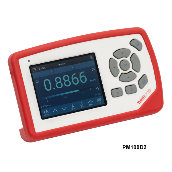 Zoom
Zoom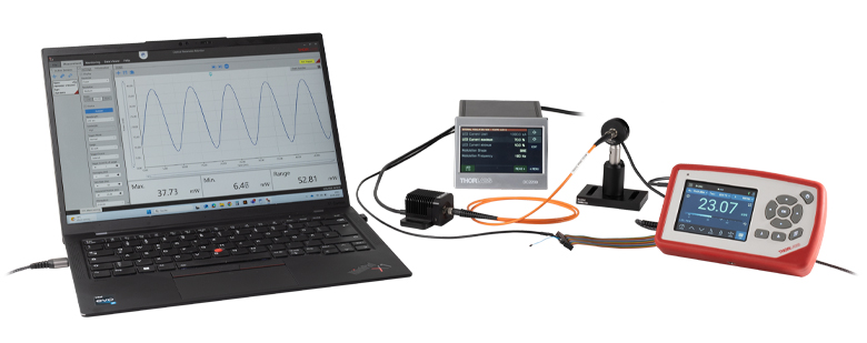
Click to Enlarge Figure G1.1 A PM100D3 power and energy meter console and S120C phototodiode sensor detect light from an MCWHF2 fiber-coupled LED, driven with a DC2200 LED driver. An input trigger from the LED driver to the 26-pin AUX connector on the PM100D3 console provides the trigger signal so the OPM software's scope mode can acquire in synchronization with the LED. A TH10K NTC thermistor is also connected to the AUX connector to allow simultaneous temperature monitoring. Note that a USB connection to the OPM software is required for the scope mode due to the high data transfer rate needed, but the PM100D3 console's Bluetooth connection can be used for all other OPM Software functionality.
- Compatible with our Photodiode, Thermal, and Pyroelectric Sensors
- PM100D3 Console Only: Compatible with Thermal Position & Power Sensors
- Screen Options: Numerical Representation with a Bar Graph, Simulated Analog Needle, Logging with a Line Graph, and Logging with Statistics
- PM100D3 Console Also Includes Wireless Charging Coil (Charger Not Included), Bluetooth®* Connectivity, Pass/Fail and Scope Screens, Three Configurable User Settings, 26-Pin AUX Connector, and a Softshell Storage Bag
The PM100D2 and PM100D3 Optical Power and Energy Meter Consoles have a large 3.5" touchscreen display with an adjustable brightness and background, and 8 GB of internal eMMC flash memory for storing data. Please note that sensors are not included with the consoles. Both consoles are compatible with >40 of our photodiode, thermal, and pyroelectric sensors, sold below. The PM100D3 console is also compatible with our thermal position and power sensors. For information about our compatible sensors, please see the sensor descriptions below. The console can also be used with custom sensors that meet the current or voltage range requirements outlined in Table 2.2 in the Specs tab.
The PM100D2 console includes four measurement screens: a numerical representation of the measured power with a bar graph, a simulated analog needle, a data logging screen with a line graph, and a data logging screen showing descriptive statistics (mean, minimum, maximum, median, Q1, and Q3) and a boxcar plot of the logged data. The PM100D3 console additionally features a pass/fail analysis and a scope screen. Pass/fail analysis is designed for use in quality control in production or service to give visual attention to whether a measurement value is within a predefined power range, without the need to read the exact power value. Relative or absolute power limits can be set by the admin user for themself and up to two other users. The scope screen is a convenient way to watch alternating or CW power signals, similarly to an oscilloscope. An external trigger signal can be input via the included 26-pin AUX connector (see the Pin Diagrams tab for details), or the sensor signal can be used as a trigger source. Please see the Interactive Demo tab for a virtual version of the device GUI for both devices with photodiode and thermal power sensor options. The PM100D3 console additionally features wireless charging (charger not included) and Bluetooth connectivity. Both consoles are compatible with Thorlabs' Optical Parameter Monitor (OPM) software, allowing all the measurements possible with the devices to be performed from a PC.
The long-life internal lithium-polymer battery on both consoles can be charged via the USB Type-C connector using the provided USB Type-C to Type-A cable and a USB power supply, such as our DS5 power supply, or a PC with a USB port. The PM100D3 console's wireless charging coil can be used with any compatible wireless charging transmitter rated at 5 W with up to 1 A (not included with purchase). Both consoles come calibrated and include the certificate of calibration; please see the Shipping List tab for a list of all included items. We recommend recalibration annually for accurate measurement results. Thorlabs offers recalibration services for the PM100Dx consoles, which can be ordered below (see Item #s CAL-PM1 or CAL-PM1D). Alternatively, if you have a corresponding sensor that needs recalibrating, you can include the PM100Dx console with the sensor for factory recalibration at no additional cost (Item # CAL-PM1 only). To order these services, scroll to the bottom of the page and select the appropriate Item # that corresponds to your sensor and desired calibration.
*Bluetooth is a registered trademark of Bluetooth Sig, Inc.
Click to Enlarge
Figure 614A S120C and CP44F Quick-Release Mount
- For General Purpose Optical Power Measurements
- Integrated Viewing Target for Easy Sensor Alignment
- Ø9.5 mm Sensor Aperture
- Sensor, Protective Cap, IR Target, and Thread Adapter Included
- Fiber Adapters Available Separately (See Table 614B)
- See the Full Web Presentation for More Information
These Standard Photodiode Power Sensors are ideal for metering low power coherent and incoherent sources from the UV to the NIR. Each NIST-Traceable, calibrated sensor features an integrated viewing target for easy alignment, enhanced shielding against electromagnetic interference, an over-temperature-alert device, and a large Ø9.5 mm sensor aperture. The sensors are compatible with 30 mm cage systems, Ø1/2" posts, and SM1 (1.035"-40) lens tubes, and are ideal for free-space and fiber-coupled sources.
Thorlabs offers recalibration services for these photodiode power sensors, which can be ordered below (see Item #s CAL-UVPD or CAL-UVPDD for UV-extended Si sensors, Item #s CAL-PD or CAL-PDD for Si sensors and Item #s CAL-IRPD or CAL-IRPDD for Ge sensors).
| Table 614B Specifications | ||||
|---|---|---|---|---|
| Item #a | S120VC | S120C | S121C | S122Ch |
| Sensor Image (Click the Image to Enlarge) |
|
|
|
|
| Aperture Size | Ø9.5 mm | |||
| Wavelength Range | 200 nm - 1100 nm | 400 nm - 1100 nm | 400 nm - 1100 nm | 700 nm - 1800 nm |
| Power Range | 50 nW - 50 mW (200 nm - 450 nm) 50 nW - 20 mW (450 nm - 1100 nm) |
50 nW - 50 mW | 500 nW - 500 mW | 50 nW - 40 mW |
| Detector Type | Si Photodiode (UV Extended) | Si Photodiode | Ge Photodiode | |
| Linearity | ±0.5% | |||
| Resolutionb | 1 nW | 10 nW | 2 nW | |
| Measurement Uncertaintyc | ±3% (440 nm - 980 nm) ±5% (280 nm - 439 nm) ±7% (200 nm - 279 nm, 981 nm - 1100 nm) |
±3% (440 nm - 980 nm) ±5% (400 nm - 439 nm) ±7% (981 nm - 1100 nm) |
±5% | |
| Responsivityd (Click for Plot) |  Raw Data |
 Raw Data |
 Raw Data |
 Raw Data |
| Coating/Diffuser | Reflective ND (OD1.5)e | Reflective ND (OD1)f | Reflective ND (OD2)g | Absorptive ND (Schott NG9) |
| Head Temperature Measurement | NTC Thermistor 4.7 kΩ | |||
| Housing Dimensions | Ø30.5 mm x 12.7 mm | |||
| Cable Length | 1.5 m | |||
| Post Mountinge,f,g | Universal 8-32 / M4 Tap, Post Not Included | |||
| Aperture Thread | External SM1 (1.035"-40) | |||
| Compatible Fiber Adapters | S120-FC2, S120-FC, S120-APC2, S120-APC, S120-SMA, S120-ST, S120-LC, and S120-SC (Not Included) | |||
| Compatible Consoles | PM100A, PM100D2, PM100D3, PM400, and PM5020 | |||
| Compatible Interfaces | PM101, PM101A, PM101R, PM101U, PM103, PM103A, PM103E, PM103U, and PM100USB | |||
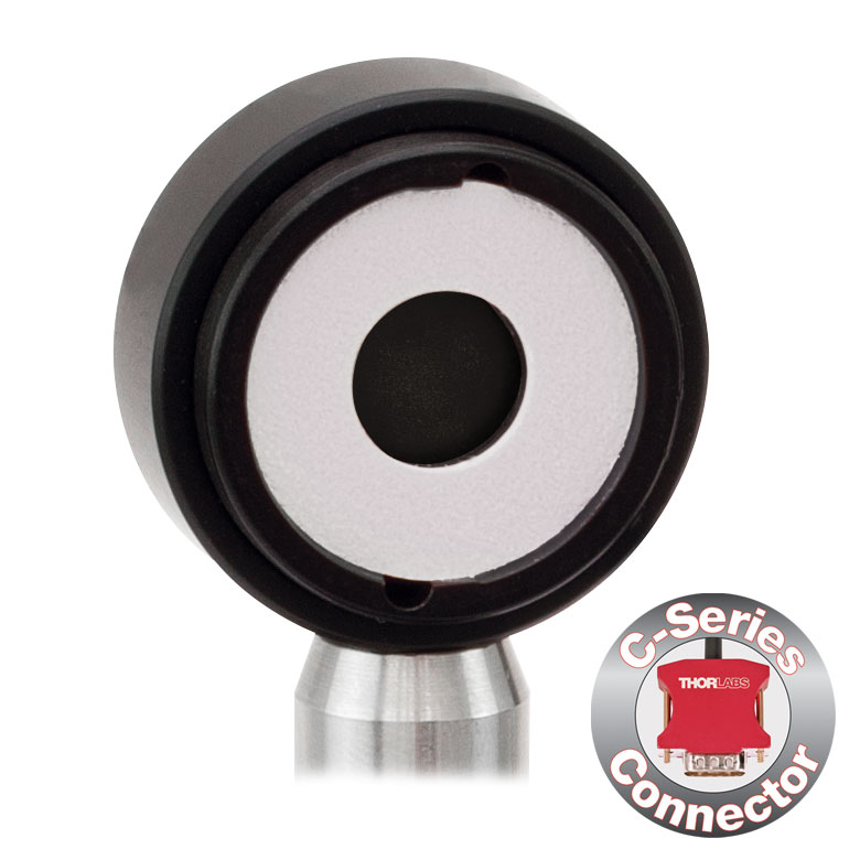

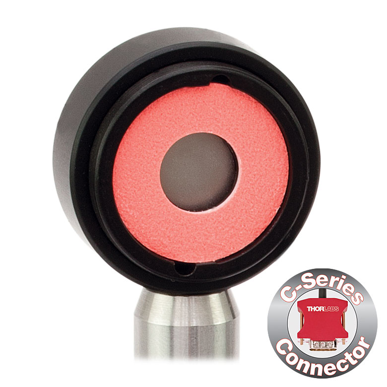


Click to Enlarge Figure 615C S130C Sensor in a 30 mm Cage
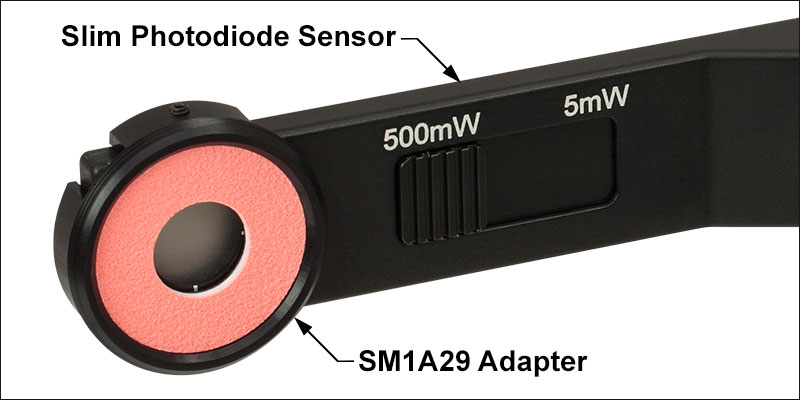
Click for Details
Figure 615B SM1A29 SM1 Thread Adapter Mounted on a S130C Sensor

Click for Details Figure 615A S130C Photodiode Sensor Mounted in FiberBench System Using FBSM Mount
- For Optical Power Measurements in Confined Spaces
- Very Slim Design: 5 mm Thin on Sensor Side
- Ø9.5 mm Sensor Aperture
- Slideable ND Filter Automatically Changes Sensor Power Range
- Optional SM1A29 Adapter with VIS/IR Target and External SM1 Threading (More Details)
- Optional FBSM Mount with VIS/IR Target for FiberBench Systems (More Details)
- See the Full Web Presentation for More Information
These Slim Photodiode Power Sensors are designed to take optical source power measurements in locations where space and accessibility are at a premium. The 5 mm thin sensor end can fit between closely spaced optics, cage systems, and other arrangements where standard power meters may not fit. The NIST-Traceable, calibrated sensors also feature a large Ø9.5 mm sensor aperture and slideable neutral density filter for dual power ranges in one compact device.
A separately available SM1A29 adapter can be attached by two setscrews to any S130 series power sensor to mount fiber adapters, light shields, filters or any other SM1-threaded (1.035"-40) mechanics or optics. The FBSM Mount allows our S130 series power sensors to be mounted vertically into FiberBench systems for stable mounting with a minimal footprint.
Thorlabs offers recalibration services for these photodiode power sensors, which can be ordered below (see Item #s CAL-UVPD2 or CAL-UVPD2D for UV-extended Si sensors, Item #s CAL-PD2 or CAL-PD2D for Si sensors, and Item #s CAL-IRPD2 or CAL-IRPD2D for Ge sensors).
| Table 615D Specifications | |||||
|---|---|---|---|---|---|
| Item #a | S130VC | S130C | S132C | ||
| Sensor Image (Click the Image to Enlarge) |
|
|
|
||
| Aperture Size | Ø9.5 mm | ||||
| Wavelength Range | 200 nm - 450 nm | 450 nm - 1100 nm | 400 nm - 1100 nm | 700 nm - 1800 nmb | |
| Power Range (with Filter) |
500 pW - 0.5 mW (Up to 50 mW)c |
500 pW - 0.2 mW (Up to 20 mW)c |
500 pW - 5 mW (Up to 500 mW) |
5 nW - 5 mW (Up to 500 mW) |
|
| Detector Type | Si Photodiode (UV Extended) | Si Photodiode | Ge Photodiode | ||
| Linearity | ±0.5% | ||||
| Resolution | 100 pWd | 1 nWe | |||
| Measurement Uncertaintyf | ±3% (440 nm - 980 nm) ±5% (280 nm - 439 nm) ±7% (200 nm - 279 nm, 981 nm - 1100 nm) |
±3% (440 nm - 980 nm) ±5% (400 nm - 439 nm) ±7% (981 nm - 1100 nm) |
±5% | ||
| Responsivityg (Click for Plot) | Raw Data |
Raw Data |
Raw Data |
||
| Coating/Diffuser | Reflective ND (OD1.5)c | Reflective ND (OD2)h | Absorptive ND (Schott NG9/KG3)b | ||
| Housing Dimensions | 150 mm x 19 mm x 10 mm; 5 mm Thickness on Sensor Side | ||||
| Cable Length | 1.5 m | ||||
| Post Mounting | 8-32 and M4 Taps | ||||
| Adapters (Not Included) | SM1A29: Add SM1 Thread and Viewing Target to Aperture Fiber Adapters Compatible with SM1A29 Adapter: S120-FC2, S120-FC, S120-APC2, S120-APC, S120-SMA, S120-ST, S120-SC, and S120-LC FBSM: Integrate Sensor into FiberBench Setups |
||||
| Compatible Consoles | PM100A, PM100D2, PM100D3, PM400, PM100USB, and PM5020 | ||||
| Compatible Interfaces | PM101, PM101A, PM101R, PM101U, PM103, PM103A, PM103E, PM103U, and PM100USB | ||||
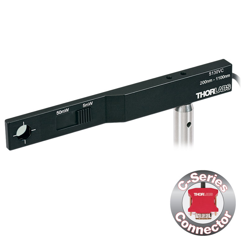
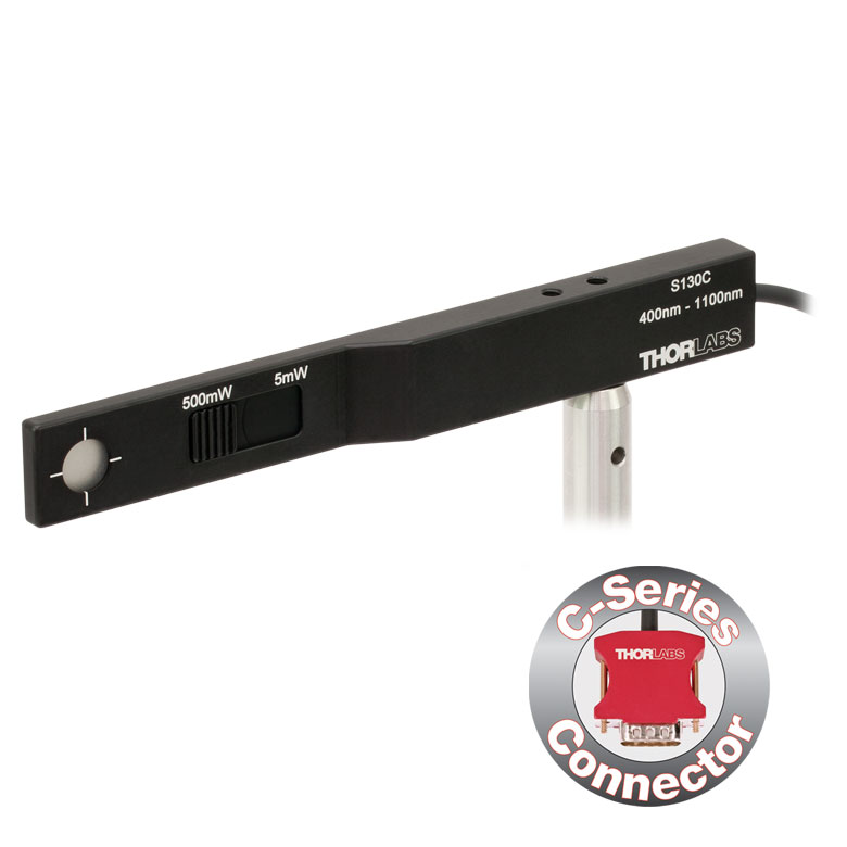
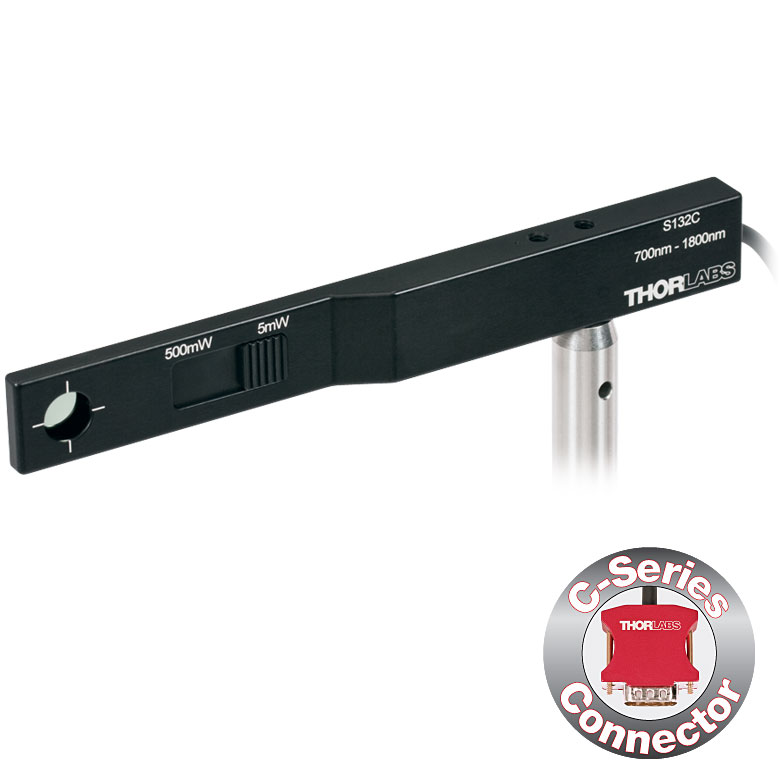
| Table 728A Specifications | ||
|---|---|---|
| Item #a | S116C | |
| Sensor Image (Click the Image to Enlarge) |
|
|
| Aperture Size | Ø6 mm | |
| Wavelength Range | 400 nm - 1100 nm | |
| Power Range | 20 nW - 50 mW | |
| Detector Type | Si Photodiode | |
| Linearity | ±0.5% | |
| Resolution | 1 nWb | |
| Measurement Uncertaintyc | ±3% (440 nm - 980 nm) ±5% (400 nm - 439 nm) ±7% (981 nm - 1100 nm) |
|
| Responsivityd (Click for Plot) |
Raw Data |
|
| Coating/Diffuser | Absorptive ND (NG9) | |
| Housing Dimensions (L x W x T) |
70.0 mm x 11.0 mm x 8.9 mm; 10.0 mm Width and 4.5 mm Thickness on Sensor Side |
|
| Active Detector Area | 7 mm x 7 mm | |
| Cable Length | 1.5 m | |
| Mounting Threads | 2 Universal 8-32 / M4 Taps (One on the Back, One on the Bottom), Posts Not Included |
|
| Adapters (Not Included) |
SM05A29: Add SM05 Thread to Aperture Fiber Adapters Compatible with SM05A29 Adapter: PM20-FC2, PM20-FC, PM20-APC2, PM20-APC, PM20-SMA, PM20-ST, PM20-SC, and PM20-LC |
|
| Compatible Consoles | PM100A, PM100D2, PM100D3, PM400, and PM5020 | |
| Compatible Interfaces | PM101, PM101A, PM101R, PM101U, PM103, PM103A, PM103E, PM103U, and PM100USB | |
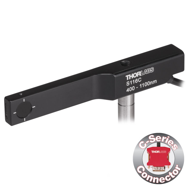
- For Optical Power Measurements in Tiny Spaces Such as 16 mm Cage Systems
- Wavelength Range: 400 - 1100 nm
- Very Slim Design: 10.0 mm Wide and 4.5 mm Thin on Sensor Side
- Silicon Photodiode with Ø6 mm Sensor Aperture
- Designed for Power Measurements for Low Power Lasers
- Post Mountable via 8-32 (M4) Taps
- SM05A29 Adapter with External SM05 (0.535"-40) Threading Available Separately (More Details)
- See the Full Web Presentation for More Information
The S116C Compact Slim Photodiode Power Sensor is designed to take optical source power measurements in locations where space and accessibility are at a premium. The 4.5 mm thin photodiode sensor can fit between the rods of a 16 mm cage system, as seen in Figure 728C, as well as through the side openings of our slotted Ø1/2" lens tubes (Item #s SM05L20C and SM05L30C). This sensor also features a Ø6 mm sensor aperture.
A separately available SM05A29 adapter can be attached by two 0.05" (1.3 mm) hex setscrews to an S116C power sensor to mount fiber adapters, light shields, filters or any other SM05-threaded (0.535"-40) mechanics or optics. The adapter mounted on the S116C power sensor is shown in Figure 728B.
Each sensor is shipped with NIST- and PTB-traceable calibration data. The included data is determined with the help of a certified reference diode, which corresponds to the spectral range of the sensor to be calibrated. Thorlabs offers recalibration services for these photodiode power sensors, which can be ordered below (see Item #s CAL-PD or CAL-PDD for Si sensors).
Click to Enlarge Figure 728C S116C Sensor in a 16 mm Cage System
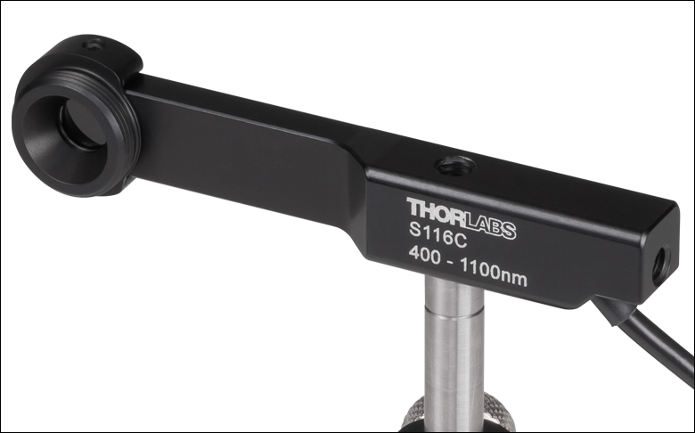
Click for Details
Figure 728B SM05A29 SM05 Thread Adapter (Sold Separately) Mounted on an S116C Sensor
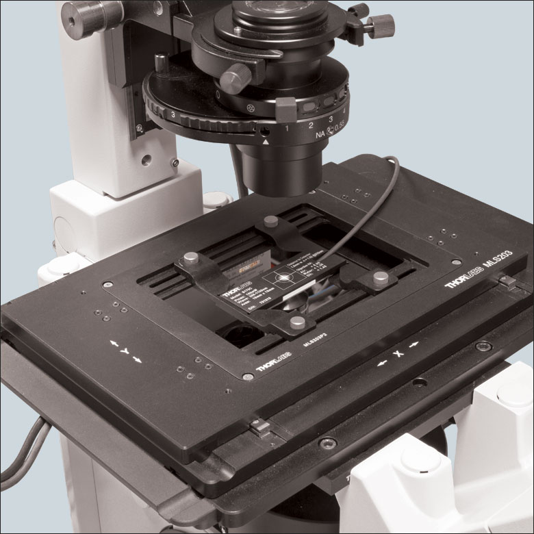
Click for Details
Figure 616A Using the engraved alignment target on the back of the sensor housing, a user can position the stage so that when the sensor is flipped, the beam strikes the center of the sensor. The S170C sensor is shown in this image.
- Designed to Measure Optical Power at the Sample Plane of a Microscope
- Silicon Photodiode with Large 18 mm x 18 mm Active Area
- Sensor Housing Dimensions: 76.0 mm x 25.2 mm x 5.0 mm
- Novel Optical Design Accommodates High NA Objectives
- Information Stored in Connector
- Sensor Data
- NIST- and PTB-Traceable Calibration Data
- Post Mountable via 8-32 (M4 x 0.7) Tap
The Microscope Slide Power Sensor Heads with silicon photodiodes are designed to measure the power at the sample plane in microscopy setups. The S170C sensor can detect wavelengths from 350 nm to 1100 nm at optical powers from 10 nW to 150 mW. The NS170C sensor is designed to measure the relative peak power of femtosecond lasers with center wavelengths from 780 nm to 1300 nm and average powers from 0.5 mW to 350 mW. Each sensor head's 76.0 mm x 25.2 mm footprint matches that of a standard microscope slide and is compatible with most standard upright and inverted microscopes.
The photodiode used in the S170C sensor has an 18 mm x 18 mm active area and is contained in a sealed housing behind a neutral density (ND) filter. A 20 mm x 20 mm indentation around the surface of the ND filter is sized to accept standard microscope cover slips. An immersion medium (water, glycerol, oil) may be placed in this well directly over the ND filter, or a cover slip may be inserted first to simplify clean up. The gap between the photodiode and the neutral density filter has been filled with an index-matching gel in order to prevent internal reflections from causing significant measurement errors when using high NA objectives with oil or water.
The NS170C sensor is designed to measure the relative peak power of two-photon lasers by utilizing a second-order nonlinear β-BBO crystal to convert incident ultrafast NIR pulses into their visible second harmonic. Shortpass filters underneath the β-BBO crystal reject the residual NIR light, allowing only the second harmonic light to transmit down to a large area silicon photodiode sensor. At the entrance of the sensor is a 170 µm thick cover glass sealed to the sensor housing, allowing the sensor to be used with dry, water immersion, and oil immersion objectives. The working distance from the top of the cover glass to the β-BBO crystal is 0.22 mm.
The bottom of each sensor housing features a laser-engraved grid to aid in aligning and focusing the beam. In standard microscopes, this grid can be used for beam alignment before flipping the sensor head to face the objective for power measurements. In inverted microscopes, turn on the transmitted illuminator to align the grid on the detector housing with the beam, thereby centering the sensor in front of the objective. Alternatively, the diffusive surface of the ND filter can be used as a focusing plane.
To avoid damaging the sensor, we recommend positioning it in the light path at a location where the beam is not focused. It is important not to exceed the Max Average Power Density over the beam's spot size for the S170C sensor, and the Max Peak Power Density for the NS170C sensor (see Specs tab).
Each sensor is shipped with NIST- or PTB-traceable calibration data. The included data will match the calibration certification of the photodiode used to test the individual sensor. Sensor specifications and the included NIST- or PTB-traceable calibration data are stored in non-volatile memory in the sensor connector and can be read out by the latest generation of Thorlabs power meters. Please note that the NS170C sensor's NIST and PTB calibration is for the visible light incident on the detector; however, the magnitude of that visible light is specific to the illumination conditions of the NIR femtosecond pulses. We recommend yearly recalibration to ensure accuracy and performance, which can be ordered below (see Item #s CAL-PD or CAL-PDD for the S170C sensor, and Item # CAL-NS for the NS170C sensor). Please contact Tech Support for more information.
The complete set of specifications are presented on the Specs tab. Thorlabs also offers a Microscope Slide Sensor Head with a thermal sensor; the full presentation can be found here.
| Item #a | S170C | NS170C |
|---|---|---|
| Sensor Image (Click Image to Enlarge) |
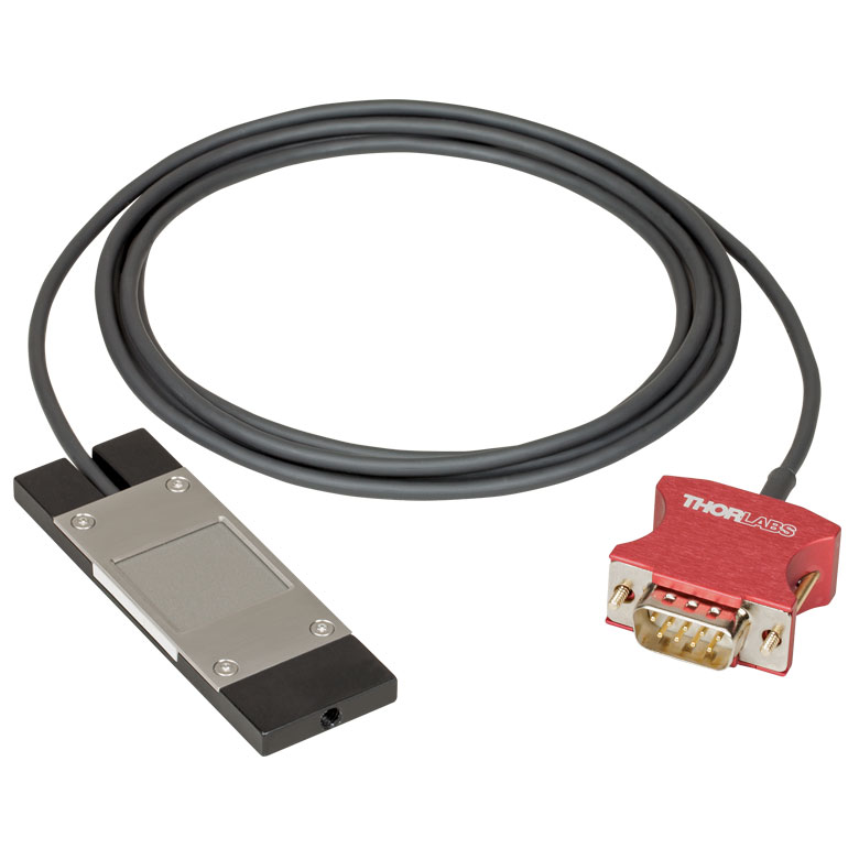 |
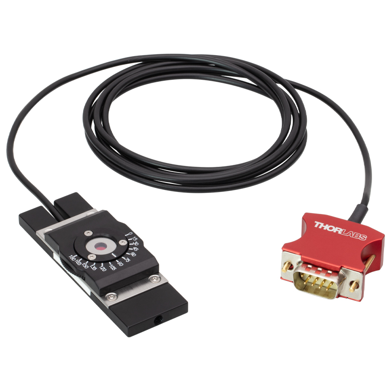 |
| Dimensions | 76.0 mm x 25.2 mm x 5.0 mm (2.99" x 0.99" x 0.20") |
Base: 76.0 mm x 25.2 mm x 5.0 mm (2.99" x 0.99" x 0.20") Overall: 76.0 mm x 30.0 mm x 11.0 mm (2.99" x 1.18" x 0.43") |
| Active Detector Area | 18 mm x 18 mm | |
| Input Aperture | 20 mm x 20 mm | Ø4.5 mm |
| Wavelength Range | 350 nm - 1100 nm | Laser: 780 nm - 1300 nm SHG: 390 nm - 650 nm |
| Optical Power Working Range | 10 nW - 150 mW | Laser: 0.5 mW - 350 mWb SHG: 10 nW - 5 mW |
| Max Peak Power Densityc | - | 10 TW/cm2 |
| Detector Type | Silicon Photodiode | Second-Order Nonlinear Crystal with Silicon Photodiode |
| Linearity | ±0.5% | ±0.5%d |
| Resolution | 1 nWe | 1 nWd,e |
| Measurement Uncertaintyf | ±3% (440 nm - 980 nm) ±5% (350 nm - 439 nm) ±7% (981 nm - 1100 nm) |
±3% (440 nm - 650 nm)d ±5% (390 nm - 439 nm)d |
| Responsivityg (Click for Plot) |
 Raw Data |
 Raw Data |
| Neutral Density Filter | Reflective (OD 1.5) | N/A |
| Cable Length | 1.5 m | |
| Mounting Thread | Universal 8-32 / M4 x 0.7 Tap, Post Not Included | |
| Compatible Consoles | PM100A, PM100D2, PM100D3, PM400, and PM5020 | |
| Compatible Interfaces | PM101, PM101A, PM101R, PM101U, PM103, PM103A, PM103E, PM103U, and PM100USB | |
| Table 617B Specifications | |
|---|---|
| Item #a | S175C |
| Sensor Image (Click Image to Enlarge) |
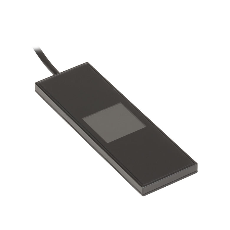 |
| Active Detector Area | 18 mm x 18 mm |
| Wavelength Range | 0.3 µm - 10.6 µm |
| Power Range | 100 µW - 2 W |
| Detector Type | Thermal Surface Absorber (Thermopile) |
| Linearity | ±0.5% |
| Resolutionb | 10 µW |
| Measurement Uncertaintyc | ±3% @ 1064 nm; ±5% @ 300 nm - 10.6 µm |
| Response Time | 3 s (<2 s from 0 to 90%) |
| Housing Dimensions | 76 mm x 25.2 mm x 4.8 mm (2.99" x 0.99" x 0.19") |
| Cable Length | 1.5 m |
| Housing Features | Integrated Glass Cover Engraved Laser Target on Back |
| Post Mounting | N/A |
| Cage Mounting | N/A |
| Aperture Thread | N/A |
| Compatible Consoles | PM100A, PM100D2, PM100D3, PM400, and PM5020 |
| Compatible Interfaces | PM101, PM101A, PM101R, PM101U, PM102, PM102A, PM102U, and PM100USB |
Click to Enlarge
Figure 617A Typical absorption curve for the S175C (glass and absorber). Note that this curve is representative, and the actual absorption across the spectrum will vary from unit to unit.

Click to Enlarge
Figure 617C The back of the S175C housing is engraved with the sensor specifications and a target for centering the beam on the sensor.
- Wavelength Range: 300 nm - 10.6 µm
- Sensitive to Optical Powers from 100 µW to 2 W
- Designed to Measure Optical Power in the Sample Plane of a Microscope
- Thermal Sensor with 18 mm x 18 mm Active Area
- 76.0 mm x 25.2 mm Footprint Matches Standard Microscope Slides
- Information Stored in Connector
- Sensor Data
- NIST- and PTB-Traceable Calibration Data
- See the Full Web Presentation for More Information
The S175C Microscope Slide Thermal Power Sensor Head is designed to measure the power at the sample in microscopy setups. The thermal sensor can detect wavelengths between 300 nm and 10.6 µm at optical powers between 100 µW and 2 W. The sensor head's 76.0 mm x 25.2 mm footprint matches that of a standard microscope slide and is compatible with most standard upright and inverted microscopes.
The thermal sensor has an 18 mm x 18 mm active area and is contained in a sealed housing behind a glass cover. An immersion medium (water, glycerol, oil) may be placed over the glass cover plate.
As seen in Figure 617C, the bottom of the sensor housing features a laser-engraved target to aid in aligning and focusing the beam. In standard microscopes, the target can be used for beam alignment before flipping the sensor head to face the objective for power measurements. In inverted microscopes, turn on the trans-illumination lamp and align the target on the detector housing with the beam; this will center the sensor in front of the objective.
Sensor specifications and the NIST- and PTB-traceable calibration data are stored in non-volatile memory in the sensor connector and can be read out by the latest generation of Thorlabs power meters. We recommend yearly recalibration to ensure accuracy and performance. Calibration may be ordered using the CAL-THPY recalibration service available below. Please contact Tech Support for more information.
Thorlabs also offers a Microscope Slide Sensor Head with a photodiode sensor for low-power, high-resolution measurements; the full presentation may be found here.
Click to Enlarge
Figure 618B S142C and S140-BFA Bare Fiber Adapter (Sold Separately)
Click to Enlarge
Figure 618A S142C with the S120-FC Fiber Adapter (Included)
- For Measurements Independent of Beam Shape and Entrance Angle
- Integrating Sphere Design Acts as a Diffuser with Minimal Power Loss
- Ø5 mm, Ø7 mm, Ø12 mm, or Ø22 mm Input Sensor Aperture
- Spheres with Apertures ≤Ø12 mm Include a Removable S120-FC Fiber Adapter (FC/PC and FC/APC)
- Fiber Adapters for Terminated and Bare Fiber (See Table 618D) are Compatible with Spheres with Apertures ≤Ø12 mm
- See the Full Web Presentation for More Information
These Integrating Sphere Photodiode Power Sensors are the ideal choice for power measurements independent of beam uniformity, divergence angle, beam shape, or entrance angle, making them excellent for use with fiber sources and off-axis free space sources. They feature enhanced shielding to avoid electromagnetic interference and an over-temperature alert sensor to warn against damage and measurement errors due to overheating of the sensor.
Our integrating spheres are designed for wavelength ranges from the visible through the NIR. Sensor heads for use between 350 and 2500 nm use a single Ø1" or Ø2" sphere made from Zenith® PTFE and feature a black housing to minimize reflected light around the entrance aperture. These sensors use either a silicon photodiode for detection in the 350 - 1100 nm range or an InGaAs photodiode for detection in the 800 - 1700 nm, 900 - 1650 nm, or 1200 - 2500 nm wavelength range.
The S180C integrating sphere for 2.9 - 5.5 µm uses two connected, gold-plated Ø20 mm spheres, with an entrance port in the first sphere and a port for the MCT (HgCdTe) detector located in the second sphere. Compared to single-sphere designs, the two-sphere configuration improves device sensitivity by minimizing the internal sphere surface area while still effectively shielding the detector from direct illumination. This design reduces the effect of input angle, divergence, and beam shape on the measurement result by effectively shielding the photodiode without the use of a baffle or other shielding mechanism.
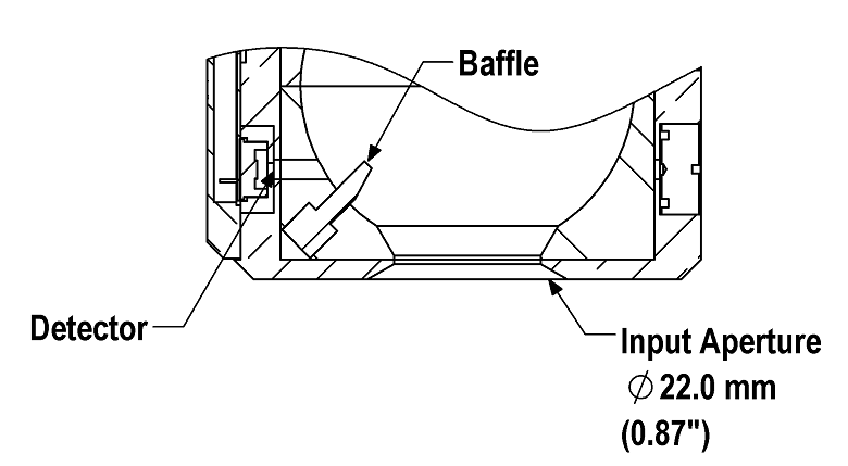
Click to Enlarge
Figure 618C A baffle on the S142CL and S145CL spheres blocks light from directly hitting the detector.
The integrating spheres with Ø5 mm, Ø7 mm, or Ø12 mm apertures feature large active detector areas, and externally SM1-threaded (1.035"-40) adapters for compatibility with the included S120-FC fiber adapter. Because of the large active detector areas of these sensors, the included S120-FC fiber adapter can be used with FC/PC- or FC/APC-terminated fiber. The externally SM1-threaded adapter can be removed using a size 1 screwdriver to place components closer to the window.
The S142CL and S145CL integrating spheres feature a large Ø22 mm input aperture and a baffle within the sphere which prevents direct illumination of the photodiode. The large aperture and baffle enable measurements of large and divergent beams, such as those emitted from LED and VCSEL light sources. The input face of the detectors have four 4-40 threads for mounting 30 mm cage system components. Additionally, insertion of a second or third port in the sensor head is possible on request, please contact Tech Support for details.
Each sensor is shipped with NIST- or PTB-traceable calibration data. The included data will match the calibration certification of the photodiode used to test the individual sensor. NIST- or PTB-traceable data is stored in the sensor connector. Thorlabs offers recalibration services for these photodiode power sensors, which can be ordered below (see Item #s CAL-PD or CAL-PDD for Si sensors, Item #s CAL-IRPD or CAL-IRPDD for InGaAs sensors, Item # CAL-MIRPD for extended InGaAs or MCT sensors, or Item # CAL-MIRPDD for extended InGaAs sensors).
| Table 618D Specifications | ||||||||||
|---|---|---|---|---|---|---|---|---|---|---|
| Item #a | S140C | S142C | S142CL | S144C | S145C | S145CL | S146C | S148C | S180C | |
| Sensor Image (Click the Image to Enlarge) |
 |
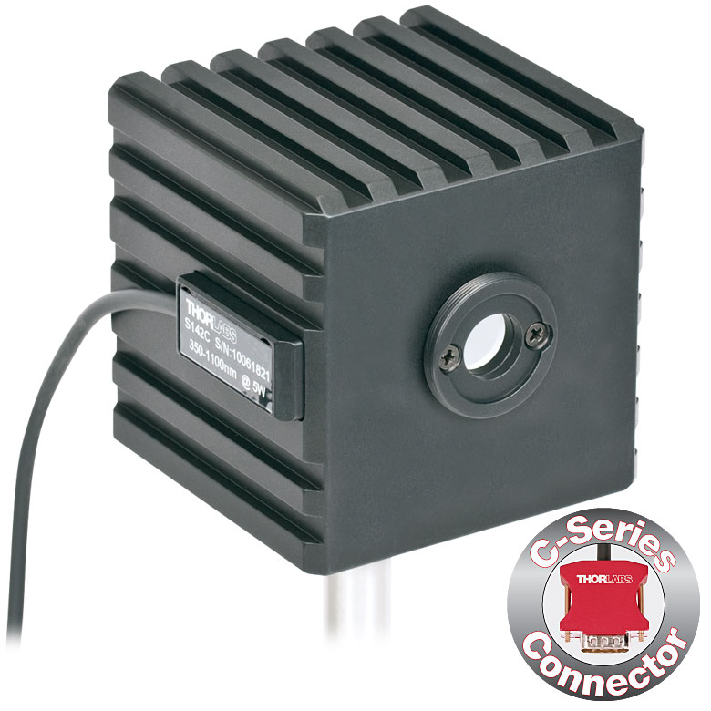 |
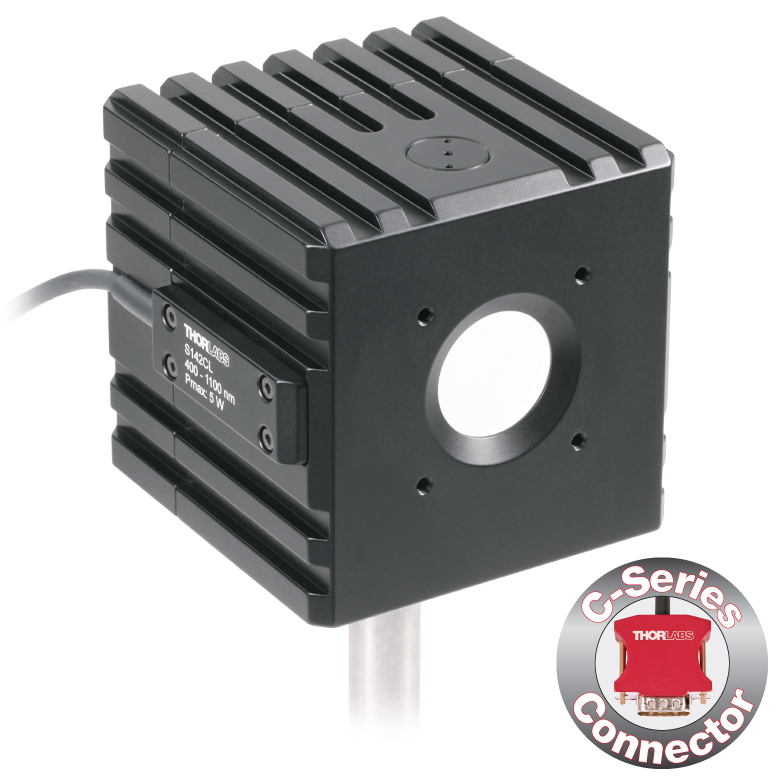 |
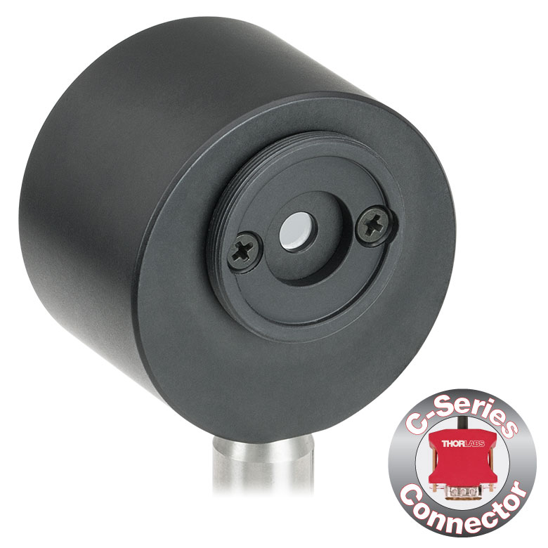 |
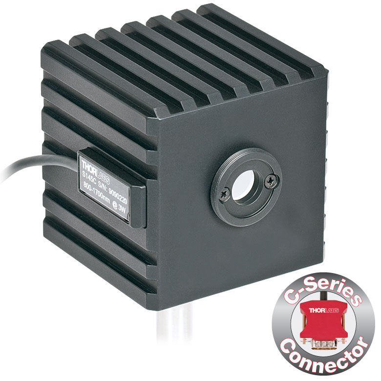 |
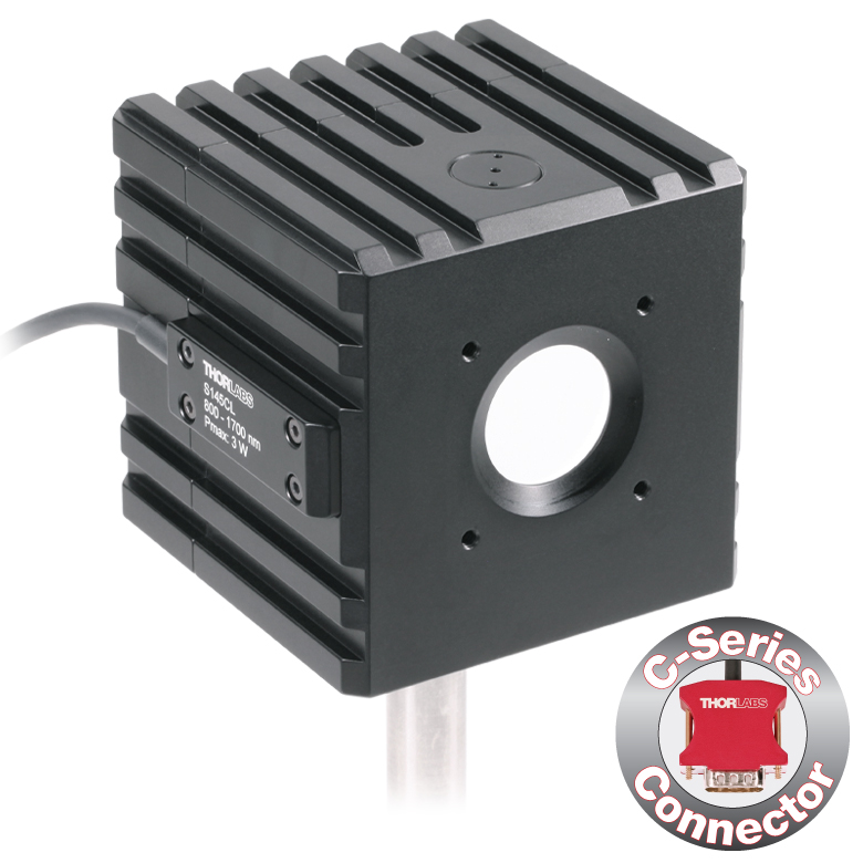 |
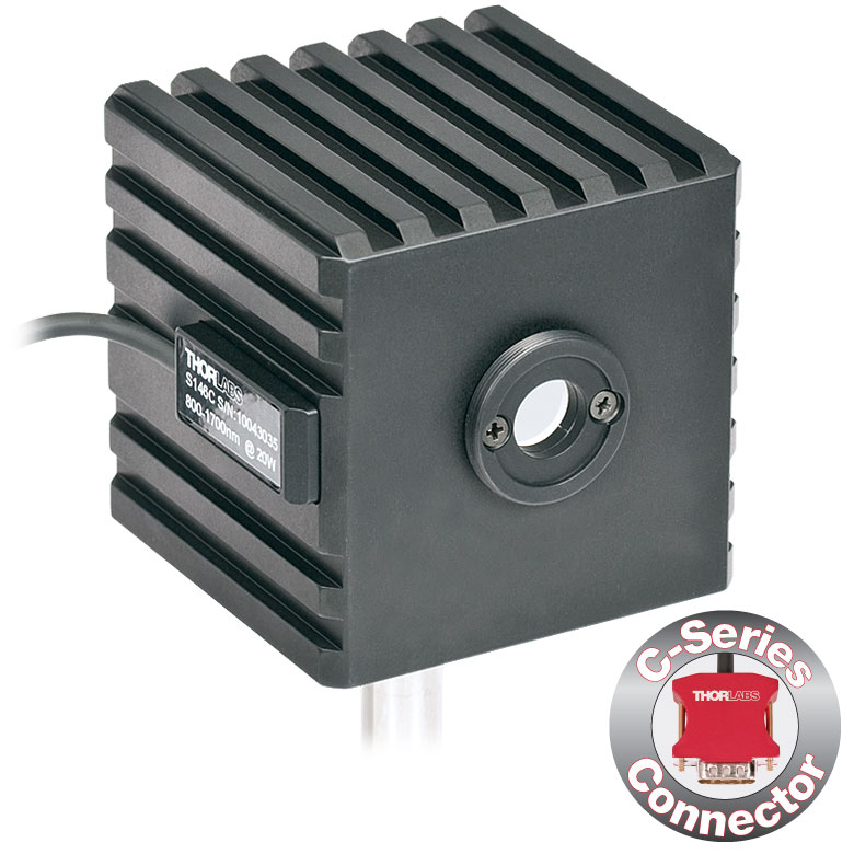 |
|
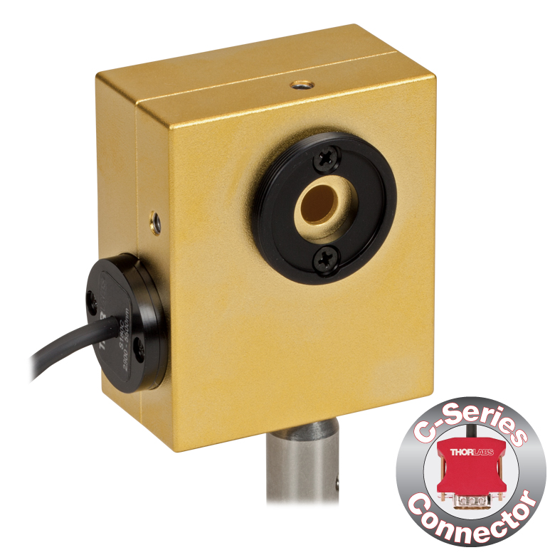 |
|
| Aperture Size | Ø5 mm | Ø12 mm | Ø22 mm | Ø5 mm | Ø12 mm | Ø22 mm | Ø12 mm | Ø5 mm | Ø7 mm | |
| Wavelength Range | 350 nm - 1100 nm | 400 nm - 1100 nm | 800 nm - 1700 nm | 900 nm - 1650 nm | 1200 nm - 2500 nm | 2.9 µm - 5.5 µm | ||||
| Power Range | 1 µW - 500 mW | 1 µW - 5 W | 10 µW - 5 W | 1 µW - 500 mW | 1 µW - 3 W | 10 µW - 3 W | 10 µW - 20 W | 1 µW - 1 W | 1 µW - 3 W | |
| Detector Type | Si Photodiode | Si Photodiode with Baffle | InGaAs Photodiode | InGaAs Photodiode with Baffle | InGaAs Photodiode | Extended InGaAs Photodiode | MCT (HgCdTe) Photodiode |
|||
| Linearity | ±0.5% | |||||||||
| Resolutionb | 1 nW | 10 nW | 1 nW | 10 nW | 1 nW | 10 nW | ||||
| Measurement Uncertaintyc,d |
±3% (440 nm - 980 nm) ±5% (350 nm - 439 nm) ±7% (981 nm - 1100 nm) |
±3% (440 nm - 980 nm) ±5% (400 nm - 439 nm) ±7% (981 nm - 1100 nm) |
±5% | |||||||
| Responsivitye (Click for Plot) |
 Raw Data |
 Raw Data |
 Raw Data |
 Raw Data |
 Raw Data |
 Raw Data |
 Raw Data |
 Raw Data |
|
| Integrating Sphere Material (Size) |
Zenith® PTFE (Ø1") |
Zenith® PTFE (Ø2") |
Zenith® PTFE (Ø1") |
Zenith® PTFE (Ø2") |
Zenith® PTFE (Ø1") |
Gold Plating (Two Ø20 mm Spheres) |
||||
| Head Temperature Measurement |
NTC Thermistor 4.7 kΩ | |||||||||
| Housing Dimensions |
Ø45 mm x 30.5 mm | 70 mm x 74 mm x 70 mm | Ø45 mm x 30.5 mm | 70 mm x 74 mm x 70 mm | Ø45 mm x 30.5 mm | 59.0 mm x 50.0 mm x 28.5 mm |
||||
| Active Detector Area | 3.6 mm x 3.6 mm | Ø2 mm | Ø3 mm | Ø1 mm | Ø1 mm | 1 mm x 1 mm | ||||
| Cable Length | 1.5 m | |||||||||
| Mounting Thread | Separate 8-32 and M4 Taps, Posts Not Included | Universal |
Separate |
Universal |
Separate |
Universal |
||||
| Aperture Thread | Included Adapter with SM1 (1.035"-40) External Thread | None | Included Adapter with SM1 (1.035"-40) External Thread | None | Included Adapter with SM1 (1.035"-40) External Thread | |||||
| Compatible Fiber Adapters |
S120-FC (Included) S120-FC2, S120-APC2, S120-APC, S120-SMA, S120-ST, S120-SC, S120-LC, S120-25, and S140-BFA (Not Included) |
None | S120-FC (Included) S120-FC2, S120-APC2, S120-APC, S120-SMA, S120-ST, S120-SC, S120-LC, S120-25, and S140-BFA (Not Included) |
None | S120-FC (Included) S120-FC2, S120-APC2, S120-APC, S120-SMA, S120-ST, S120-SC, S120-LC, S120-25, and S140-BFA (Not Included) |
|||||
| Compatible Consoles | PM100A, PM100D2, PM100D3, PM400, and PM5020 | |||||||||
| Compatible Interfaces | PM101, PM101A, PM101R, PM101U, PM103, PM103A, PM103E, PM103U, and PM100USB | |||||||||
Click to Enlarge
Figure 619A PM100D2 with S150C Sensor and FC Cable
- For Fiber-Based Optical Power Measurements
- Compact Sensor Integrated into the Connector
- Integrated Design for Use in the Field and Lab
- Includes PM20-FC Fiber Adapter
- S150C and S151C Sensors also Include PM20-SMA Adapters
- Compatible FC/APC, LC/PC, SC/PC, and ST®* Fiber Adapters Also Available (See Table 619B)
- See the Full Web Presentation for More Information
The S15xC Compact Fiber Photodiode Power Sensor is designed to take power measurements from a wide variety of fiber coupled sources. The compact sensor, integrated into the power meter connector, features a unique integrated design housing the photodiode sensor, fiber coupling, and NIST-traceable data. Standard FC (and SMA - S150C and S151C) connectors are easily interchanged with a variety of standard fiber connectors.
Thorlabs offers recalibration services for these photodiode power sensors, which can be ordered below (see Item #s CAL-PD or CAL-PDD for Si sensors and Item #s CAL-IRPD or CAL-IRPDD for InGaAs sensors).
*ST® is a registered trademark of Lucent Technologies, Inc.
| Table 619B Specifications | ||||
|---|---|---|---|---|
| Item #a | S150C | S151C | S154C | S155C |
| Sensor Image (Click the Image to Enlarge) |
|
|
|
|
| Included Connectors | FCb & SMA | FCb | ||
| Wavelength Range | 350 nm - 1100 nm | 400 nm - 1100 nm | 800 nm - 1700 nm | |
| Power Range | 100 pW to 5 mW (-70 dBm to +7 dBm) |
1 nW to 20 mW (-60 dBm to +13 dBm) |
100 pW to 3 mW (-70 dBm to +5 dBm) |
1 nW to 20 mW (-60 dBm to +13 dBm) |
| Detector Type | Si Photodiode | InGaAs Photodiode | ||
| Linearity | ±0.5% | |||
| Resolutionc | 10 pW (-80 dBm) | 100 pW (-70 dBm) | 10 pW (-80 dBm) | 100 pW (-70 dBm) |
| Measurement Uncertaintyd | ±3% (440 nm - 980 nm) ±5% (350 nm - 439 nm) ±7% (981 nm - 1100 nm) |
±3% (440 nm - 980 nm) ±5% (400 nm - 439 nm) ±7% (981 nm - 1100 nm) |
±5% | |
| Responsivityf (Click for Details) |  Raw Data |
 Raw Data |
 Raw Data |
 Raw Data |
| Coating/Diffuser | N/A | Absorptive ND (Schott NG3) | N/A | |
| Head Temperature Measuremente | NTC Thermistor 3 kΩ | |||
| Aperture Thread | External SM05 |
|||
| Fiber Adapters | Included: PM20-FC and PM20-SMA Optional: PM20-FC2, PM20-APC2, PM20-APC, PM20-ST, PM20-SC, and PM20-LC |
Included: PM20-FC Optional: PM20-FC2, PM20-APC2, PM20-APC, PM20-SMA, PM20-ST, PM20-SC, and PM20-LC |
||
| Compatible Consoles | PM100A, PM100D2, PM100D3, PM400, and PM5020 | |||
| Compatible Interfaces | PM101, PM101A, PM101R, PM101U, PM103, PM103A, PM103E, PM103U, and PM100USB | |||

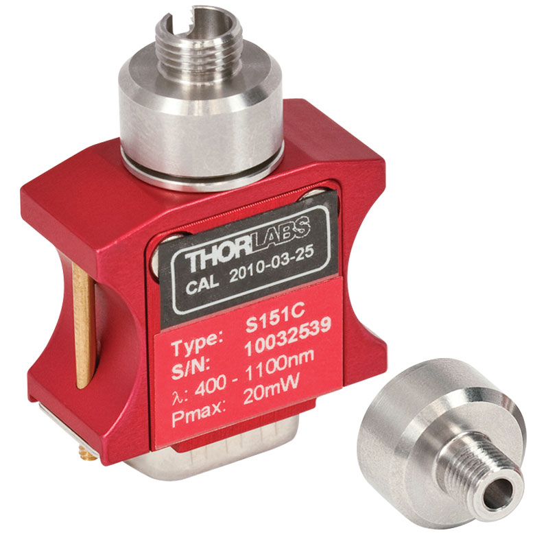
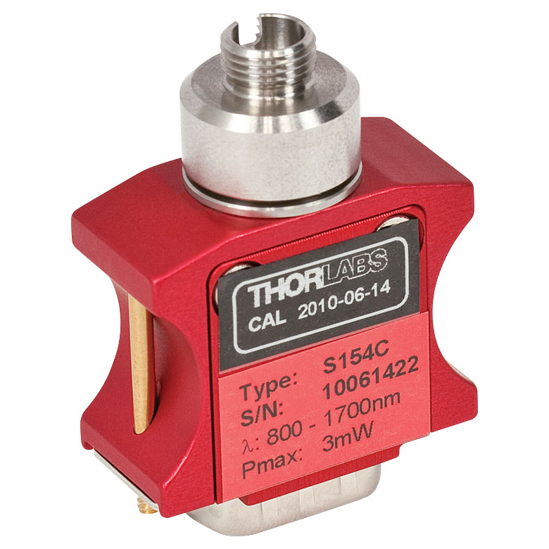

| Table 624A Specifications | ||
|---|---|---|
| Item #a | S401C | S405C |
| Sensor Image (Click the Image to Enlarge) |
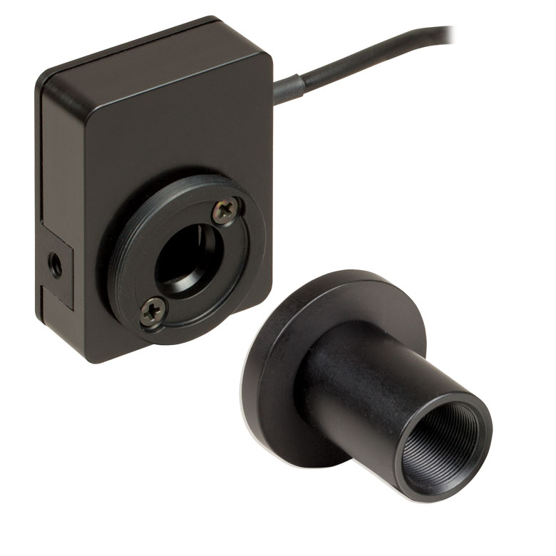 |
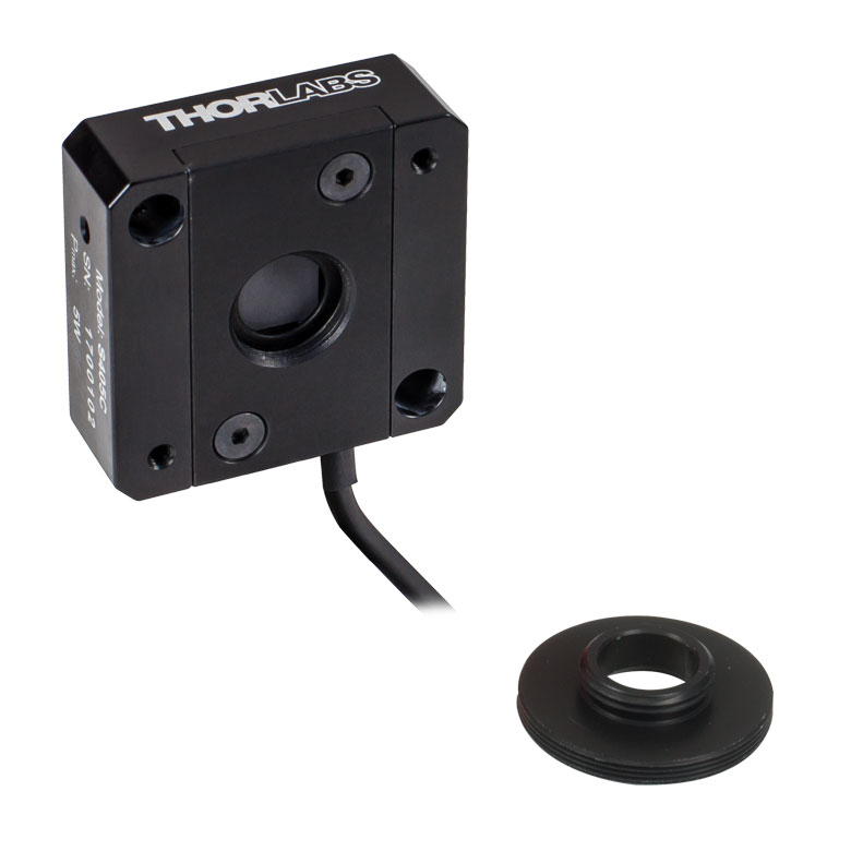 |
| Wavelength Range | 190 nm - 20 µm | 190 nm - 20 µm |
| Optical Power Range | 10 µW - 1 W (3 Wb) | 100 µW - 5 W |
| Input Aperture Size | Ø10 mm | Ø10 mm |
| Active Detector Area |
10 mm x 10 mm | 10 mm x 10 mm |
| Max Optical Power Density | 500 W/cm2 (Avg.) | 1.5 kW/cm2 (Avg.) |
| Detector Type | Thermal Surface Absorber (Thermopile) with Background Compensation |
Thermal Surface Absorber (Thermopile) |
| Linearity | ±0.5% | ±0.5% |
| Resolutionc | 1 µW | 5 µW |
| Measurement Uncertaintyd | ±3% @ 1064 nm ±5% @ 190 nm - 10.6 µm |
±3% @ 1064 nm ±5% @ 250 nm - 17 µm |
| Response Timee | 1.1 s | 1.1 s |
| Cooling | Convection (Passive) | |
| Housing Dimensions (Without Adapter) |
33.0 mm x 43.0 mm x 15.0 mm (1.30" x 1.69" x 0.59") |
40.6 mm x 40.6 mm x 16.0 mm (1.60" x 1.60" x 0.63") |
| Temperature Sensor (In Sensor Head) |
NTC Thermistor | NTC Thermistor |
| Cable Length | 1.5 m | |
| Post Mounting | Universal 8-32 / M4 Taps (Post Not Included) |
Universal 8-32 / M4 Taps (Post Not Included) |
| 30 mm Cage Mounting | - | Two 4-40 Tapped Holes & Two Ø6 mm Through Holes |
| Aperture Threads | - | Internal SM05 |
| Accessories | Externally SM1-Threaded Adapter Light Shield with Internal SM05 Threading |
Externally SM1-Threaded Adapter |
| Compatible Consoles | PM100A, PM100D2, PM100D3, PM400, and PM5020 | |
| Compatible Interfaces | PM101, PM101A, PM101R, PM101U, PM102, PM102A, PM102U, and PM100USB | |
- High Resolution of 1 μW or 5 μW
- S401C and S405C Have Thermistors Used to Monitor Temperature of Sensor Head
- S401C: Background Compensation for Low-Drift Measurements
- S405C: Accommodates Average Optical Power Densities Up to 1.5 kW/cm2;
- See the Full Web Presentation for More Information
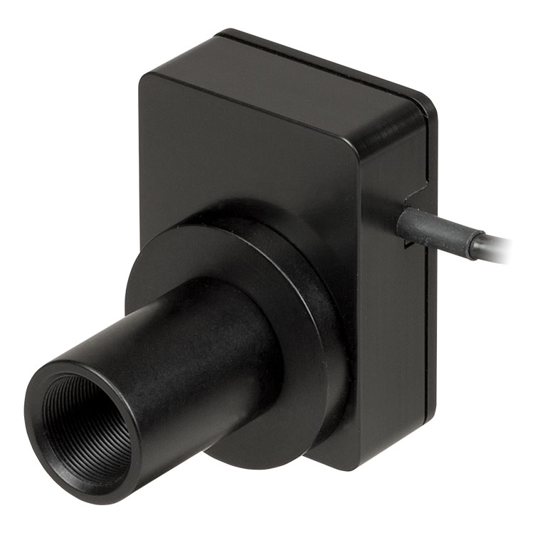
Click to Enlarge
Figure 624B S401C Thermal Sensor with Included Light Shield
Thorlabs offers two broadband thermal power sensors designed to measure low optical power sources with high resolution. Each thermal sensor's broadband coating has a flat spectral response over a wide wavelength range, as shown in Figure 624C.
An aperture size of Ø10 mm allows for easy alignment and measurement of large-spot-size laser sources. For easy integration with Thorlabs' lens tube systems and SM1-threaded (1.035"-40) fiber adapters, each sensor has either external SM1 threading or includes an externally SM1-threaded adapter.
The S401C uses active thermal background compensation to provide low-drift power measurements. This is implemented through the use of two similar sensor circuits. One sensor circuit is the type all thermal power sensors share: it measures heat flow from light absorber to heat sink. The other sensor circuit monitors the ambient temperature. It is located within the housing and measures heat flow from heat sink towards the absorber. The measurements of the two sensor circuits are subtracted, which minimizes the effect of thermal drift on the laser power measurement. (For information about how the external thermal disturbances can affect thermal power sensor readings, see the Operation tab.) The broadband coating used on this thermal sensor offers high absorption at wavelengths between 0.19 and 20 µm (shown in the graph), which makes the sensor ideal for use with aligning and measuring Mid-IR Quantum Cascade Lasers (QCLs). The included, internally SM05-threaded (0.535"-40) light shield is shown in Figure 624B.
The S405C has internal SM05 (0.535"-40) threading that is directly compatible with SM05 lens tubes, and it can also connect directly to Thorlabs' 30 mm Cage Systems.
Thorlabs offers a recalibration service for these sensors, which can be ordered below (see Item # CAL-THPY).
Click to Enlarge
Figure 624C The S405 shares the same absorption curve with the S415C, S425C, and S245C-L. (All are sold below.)
| Table 620A Specifications | ||
|---|---|---|
| Item #a | S415C | S425C |
| Sensor Image (Click Image to Enlarge) |
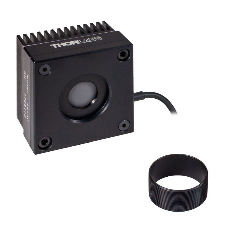 |
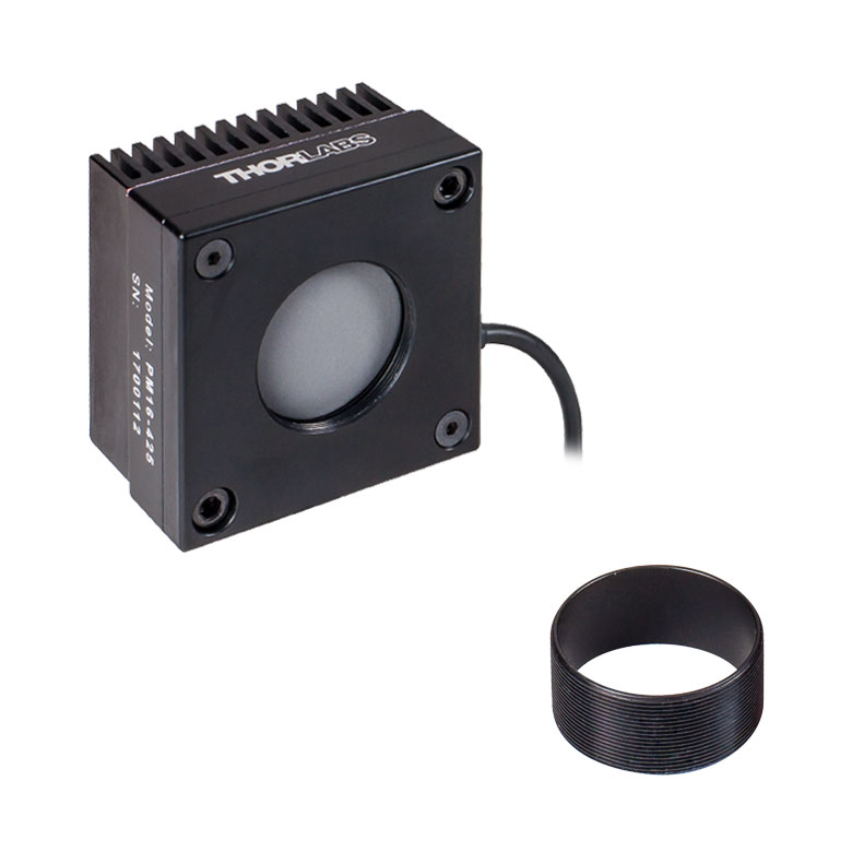 |
| Wavelength Range | 190 nm - 20 µm | 190 nm - 20 µm |
| Optical Power Range | 2 mW - 10 W (20 Wb) | 2 mW - 10 W (20 Wb) |
| Input Aperture Size | Ø15 mm | Ø25.4 mm |
| Active Detector Area |
Ø15 mm | Ø27 mm |
| Max Optical Power Density |
1.5 kW/cm2 (Avg.) | 1.5 kW/cm2 (Avg.) |
| Detector Type | Thermal Surface Absorber (Thermopile) | |
| Linearity | ±0.5% | ±0.5% |
| Resolutionc | 100 µW | 100 µW |
| Measurement Uncertaintyd |
±3% @ 1064 nm ±5% @ 250 nm - 17 µm |
±3% @ 1064 nm ±5% @ 250 nm - 17 µm |
| Response Timee | 0.6 s | 0.6 s |
| Cooling | Convection (Passive) | |
| Housing Dimensions (Without Adapter) |
(2.00" x 2.00" x 1.38") |
(2.00" x 2.00" x 1.38") |
| Temperature Sensor (In Sensor Head) |
NTC Thermistor | |
| Cable Length | 1.5 m | |
| Post Mounting | Universal 8-32 / M4 Taps (Post Not Included) |
Universal 8-32 / M4 Taps (Post Not Included) |
| 30 mm Cage Mounting | - | - |
| Aperture Threads | Internal SM1 | Internal SM1 |
| Removable Heatsink | Yes | Yes |
| Accessories | Externally SM1-Threaded Adapter | Externally SM1-Threaded Adapter |
| Compatible Consoles | PM100A, PM100D2, PM100D3, PM400, and PM5020 | |
| Compatible Interfaces | PM101, PM101A, PM101R, PM101U, PM102, PM102A, PM102U, and PM100USB | |
- 100 µW Optical Power Resolution
- Thermistors Used to Monitor Temperature of Sensor Head
- Removable Heat Sinks Included
- See the Full Web Presentation for More Information
These thermal power sensors are designed for general broadband power measurements of low and medium power light sources. All include an externally SM1-threaded (1.035"-40) adapter, with threading concentric with the input aperture. The adapters are useful for mounting Ø1" Lens Tubes and Fiber Adapters (available below). The apertures of the S415C and S425C have internal SM1 threading.
These sensors operate with fast (<0.6 s) natural response times, and their removable heat sinks provide a high degree of flexibility to those interested in integrating them into custom setups or replacing the included heat sink with one that is water or fan cooled. If replacing the heat sink, please note that the replacement must provide heat dissipation adequate for the application.
Thorlabs offers a recalibration service for these sensors, which can be ordered below (see Item # CAL-THPY).

Click to Enlarge
Figure 620B The absorption curves of each of the thermal power sensors designed for use with low and medium power optical sources.
Click to Enlarge
Figure 621A The absorption curves of each of the thermal power sensors designed for use with low and medium power optical sources.
- Thermistors Used to Monitor Temperature of Sensor Head
- S322C Has 4-40 Taps for Use with Our 30 mm Cage Systems
- S350C Has Ø40 mm Aperture Well Suited to Excimer and Other Lasers with Large Spot Sizes
- S425C-L Features Removable Heat Sink
- S322C is Fan Cooled with an Optical Power Range Up to 200 W
- See the Full Web Presentation for More Information
These thermal power sensors are designed for general broadband power measurements of low and medium power light sources. With the exception of the S350C, all include an adapter with external SM1 (1.035"-40) threading concentric with the input aperture. This allows the sensors to be integrated into existing Ø1" lens tube systems in addition to being compatible with fiber adapters (available below). The aperture of the S425C-L has internal SM1 threading.
The S425C-L operates with a fast (<0.6 s) natural response time and has a removable heat sink, which provides a high degree of flexibility to those interested in integrating them into custom setups or replacing the included heat sink with one that is water or fan cooled. If replacing the heat sink, please note that the replacement must provide heat dissipation adequate for the application.
Thorlabs offers a recalibration service for these sensors, which can be ordered below (see Item # CAL-THPY).
| Table 621B Specifications | |||
|---|---|---|---|
| Item #a | S350C | S425C-L | S322C |
| Sensor Image (Click Image to Enlarge) |
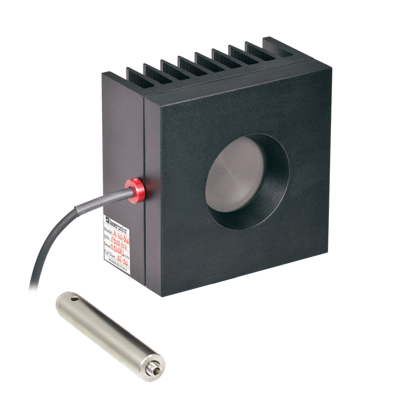 |
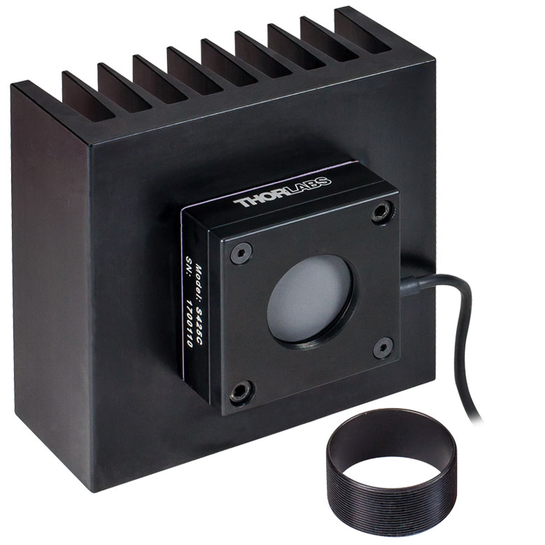 |
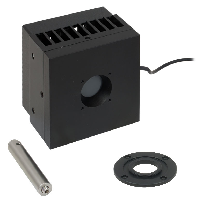 |
| Wavelength Range | 190 nm - 1.1 µm, 10.6 µm | 190 nm- 20 µm | 250 nm - 11 µm |
| Optical Power Range | 10 mW - 40 W (60 Wb) | 2 mW - 50 W (75 Wb) | 100 mW - 200 W (250 Wb) |
| Input Aperture Size | Ø40 mm | Ø25.4 mm | Ø25 mm |
| Active Detector Area |
Ø40 mm | Ø27 mm | Ø25 mm |
| Max Optical Power Density | 2 kW/cm2 (Avg.) | 1.5 kW/cm2 (Avg.) | 4 kW/cm2 (Avg., CO2) |
| Detector Type | Thermal Surface Absorber (Thermopile) | ||
| Linearity | ±1% | ±0.5% | ±1% |
| Resolutionc | 1 mW | 100 µW | 5 mW |
| Measurement Uncertaintyd | ±3% @ 1064 nm ±5% @ 190 nm - 1100 nm, 10.6 µm |
±3% @ 1064 nm ±5% @ 250 nm - 17 µm |
±3% @ 1064 nm ±5% @ 266 nm - 1064 nm |
| Response Timee | 9 s (1 s from 0 to 90%) |
0.6 s | 5 s (1 s from 0 to 90%) |
| Cooling | Convection (Passive) | Forced Air with Fanf | |
| Housing Dimensions (Without Adapter, if Applicable) |
100 mm x 100 mm x 54.2 mm (3.94" x 3.94" x 2.13") |
100.0 mm x 100.0 mm x 58.0 mm (3.94" x 3.94" x 2.28") |
100 mm x 100 mm x 86.7 mm (3.94" x 3.94" x 3.41") |
| Temperature Sensor (In Sensor Head) |
NTC Thermistor | ||
| Cable Length | 1.5 m | ||
| Post Mounting | M6 Threaded Taps, Includes Ø1/2" Post, 75 mm Long |
Universal 8-32 / M4 Taps (Post Not Included) |
M6 Threaded Taps, Includes Ø1/2" Post, 75 mm Long |
| 30 mm Cage Mounting | - | - | Four 4-40 Tapped Holes |
| Aperture Threads | - | Internal SM1 | - |
| Removable Heatsink | - | Yes | - |
| Accessories | - | Externally SM1-Threaded Adapter | Externally SM1-Threaded Adapter |
| Compatible Consoles | PM100A, PM100D2, PM100D3, PM400, and PM5020 | ||
| Compatible Interfaces | PM101, PM101A, PM101R, PM101U, PM102, PM102A, PM102U, and PM100USB | ||
| Table 622A Specifications | ||
|---|---|---|
| Item #a | S370C | S470C |
| Sensor Image (Click the Image to Enlarge) |
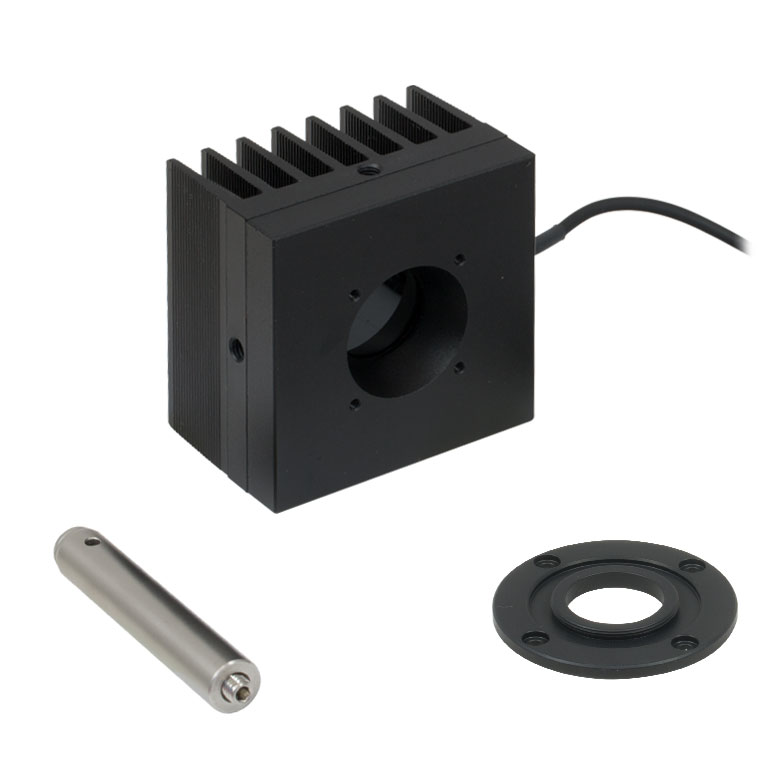 |
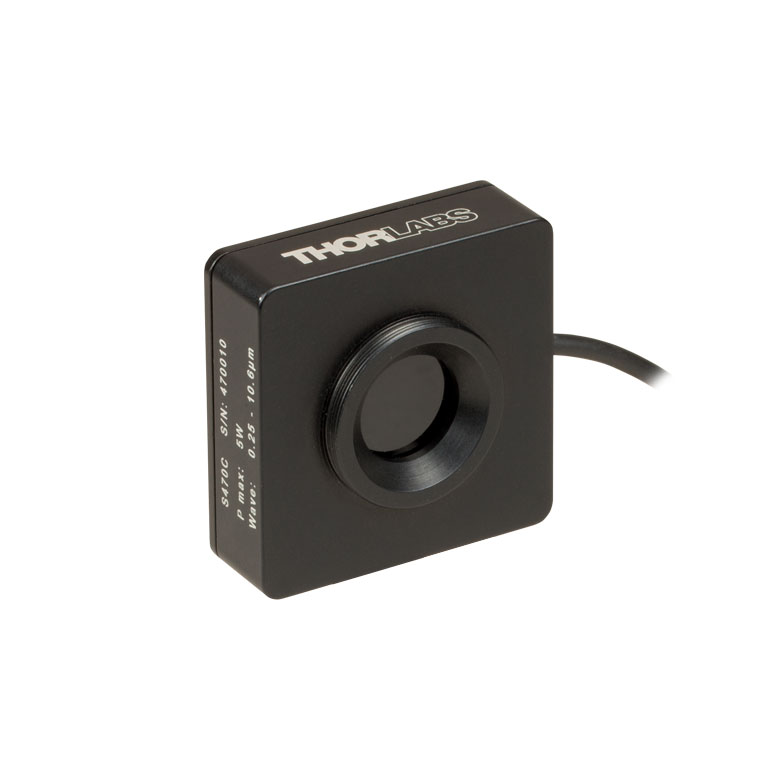 |
| Wavelength Range | 400 nm - 5.2 µm | 250 nm - 10.6 µm |
| Optical Power Range | 10 mW - 10 W (15 Wb) | 100 µW - 5 W (Pulsed and CW) |
| Input Aperture Size | Ø25 mm | Ø15 mm |
| Active Detector Area |
Ø25 mm | Ø16 mm |
| Max Optical Power Density | 35 W/cm2 (Avg.); 100 GW/cm2 (Peak) | |
| Detector Type | Thermal Volume Absorber (Thermopile) | |
| Linearity | ±1% | ±0.5% |
| Resolutionc | 250 µW | 10 µW |
| Measurement Uncertaintyd | ±3% @ 1064 nm ±5% @ 400 nm - 1064 nm |
±3% @ 1064 nm ±5% @ 250 nm - 10.6 µm |
| Response Timee | 45 s (3 s from 0 to 90%) |
6.5 s (<2 s from 0 to 90%) |
| Cooling | Convection (Passive) | |
| Housing Dimensions (Without Adapter, if Applicable) |
(2.95" x 2.95" x 2.02") |
(1.77" x 1.77" x 0.71") |
| Temperature Sensor (In Sensor Head) |
N/A | N/A |
| Cable Length | 1.5 m | |
| Post Mounting | M6 Threaded Taps, Includes Ø1/2" Post, 75 mm Long |
Universal 8-32 / M4 Tap (Post Not Included) |
| 30 mm Cage Mounting | Four 4-40 Tapped Holes | - |
| Aperture Threads | - | External SM1 |
| Accessories | - | |
| Compatible Consoles | PM100A, PM100D2, PM100D3, PM400, and PM5020 | |
| Compatible Interfaces | PM101, PM101A, PM101R, PM101U, PM102, PM102A, PM102U, and PM100USB | |
- Designed for Optical Power Measurements of Nd:YAG Lasers
- Ideal for Applications with High Peak Pulse Powers
- S370C: Ø25 mm Aperture for Large-Spot-Size Beams
- S470C: High-Sensitivity for High-Peak-Power Pulses with Low Average Power
- See the Full Web Presentation for More Information
The S370C and S470C Thermal Sensors are designed to measure short and highly energetic laser pulses. All of these units are post-mountable for free-space applications and feature NIST-traceable data stored in the sensor connector.
These thermal power sensors are unique in that they have thermal volume absorbers, where our other thermal power sensors have thermal surface absorbers. The volume absorber consists of a Schott glass filter. Incident pulses are absorbed and the heat is distributed throughout the volume. In this way, pulses that would have damaged the absorption coating of a thermal surface absorber are safely measured by these thermal volume absorbers.
The S370C features a large Ø25 mm aperture ideal for large-spot-size beams, and it is compatible with average powers from 10 mW to 10 W (CW).
In comparison, the S470C is faster, as the glass absorber volume is reduced and other design parameters have been optimized for speed. This results in a different optical power range, with the ability to measure powers down to 100 µW. The Ø15 mm aperture of the S470C is smaller, and has a lower max average power of 5 W. Its 10 µW resolution is better than the 250 µW resolution of the S370C.
Thorlabs offers a recalibration service for these sensors, which can be ordered below (see Item # CAL-THPY).
Click to Enlarge
Figure 622B This absorption curve is shown over a broader wavelength range than the sensors' operating ranges. See Table 622A for the operating wavelength range of each sensor.
| Item #a | S440C | S442C |
|---|---|---|
| Sensor Image (Click the Image to Enlarge) |
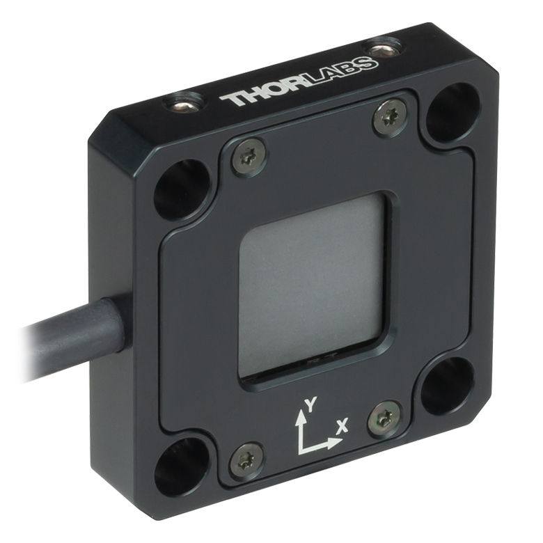 |
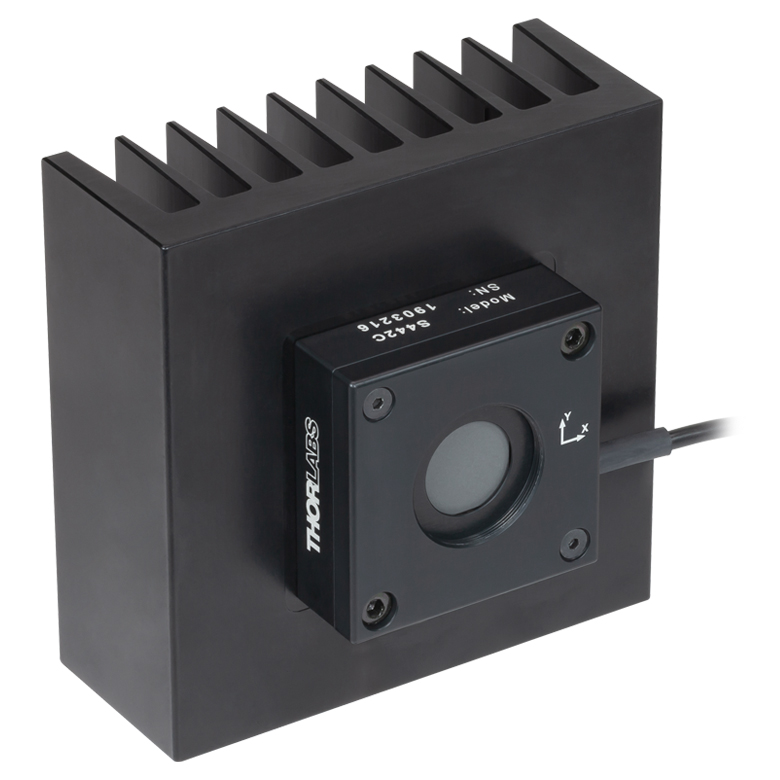 |
| Wavelength Range | 190 nm - 20 µm | |
| Optical Power Range | 0.5 mW - 5 W | 10 mW - 50 W |
| Input Aperture Size | 17 mm x 17 mm | Ø17.5 mm |
| Max Optical Power Density | 1.5 kW/cm2 | |
| Detector Type | Four Thermopiles in Quadrant Configuration | |
| Linearity | ±1% | |
| Resolutionb | 50 µW | 1 mW |
| Measurement Uncertaintyc | ±5% at 1064 nm; ±7% for 250 nm - 17 µm |
|
| Position Resolution | 5 µm | 10 µm |
| Position Accuracyd | 50 µm (Ø1 mm Circle) 200 µm (Ø6 mm Circle) |
100 µm (Ø1 mm Circle) 300 µm (Ø6 mm Circle) |
| Position Repeatabilityd | 15 µm (Ø1 mm Circle) 100 µm (Ø6 mm Circle) |
25 µm (Ø1 mm Circle) 150 µm (Ø6 mm Circle) |
| Response Timee | <1.1 s | <0.6 s |
| Cooling | Convection (Passive) | |
| Housing Dimensions (Without Adapter) |
40.6 mm x 40.6 mm x 8.9 mm (1.60" x 1.60" x 0.35") |
100.0 m x 100.0 mm x 57.8 mm (3.94" x 3.94" x 2.28") |
| Temperature Sensor (In Sensor Head) |
NTC Thermistor | |
| Cable Length | 1.5 m | |
| Post Mounting | One 8-32 / M4 Universal Tap | Two 8-32 / M4 Universal Taps |
| 30 mm Cage Mounting | Four Ø6 mm Through Holes | - |
| Aperture Threads | - | Internal SM1 (1.035"-40) |
| Accessories | - | Externally SM1-Threaded Adapter |
| Compatible Consoles | PM100D3, PM400 or PM5020 | |
| Compatible Interfaces | PM102, PM102A, or PM102U | |
- Segmented Quadrant Position-Sensing Detector
- S440C: High Sensitivity; 30 mm Cage System Compatible
- S442C: High Power; Heat Sink Included
- See the Full Web Presentation for More Information
The S440C and S442C position sensors use thermopiles to obtain high-resolution measurements of a beam's position and power. The detector area consists of four thermopile-based sensors arranged as quadrants of a square. The quadrants are mechanically coupled but electrically isolated; thus, heat is free to flow across the entire active area, but the signal from each quadrant measures the response in only that quadrant's thermopile. The XY position of the beam is determined by comparing the signal intensity measured for each quadrant.
The S440C detector is optimized for high sensitivity from 0.5 mW to 5 W. The housing features four Ø6 mm through holes for compatibility with 30 mm cage systems, as well as an 8-32 / M4 universal tap for post mounting. The S442C detector is compatible with higher power levels from 10 mW up to 50 W. The housing includes a heat sink for superior heat dissipation, as well as two 8-32 / M4 universal taps for post mounting.
Both detectors feature C-Series connectors which contain NIST- and PTB-traceable calibraion data. The sensors can be controlled using the PM100D3, PM400, or PM5020 power meter consoles or PM102 series power meter interfaces. The system can be configured to display a visual trace of the position over time, a graph of the X and Y positions over time, a table of measurement statistics, or a simple numerical readout of the incident power. See the PM100D3 and PM400 full web presentations and the PM100D3 manual and PM400 manual for details.
For information on recalibration services for these products, please contact Tech Support.
Click to Enlarge
Click Here for Raw Data
Figure 690A The wavelength range of the data in this graph is limited by the detector used during testing. The thermal position detectors are capable of operating at up to 20 µm.
| Table 623A Specifications | |||
|---|---|---|---|
| Item #a | ES111C | ES120C | ES145C |
| Sensor Image (Click the Image to Enlarge) |
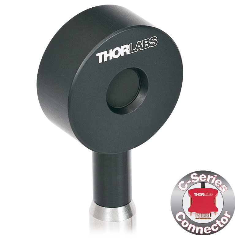 |
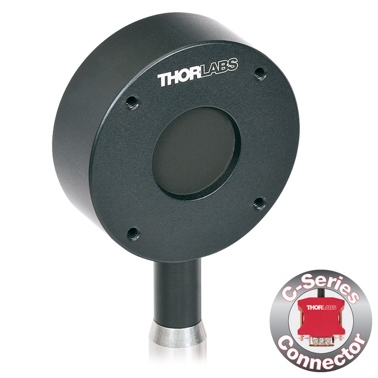 |
 |
| Input Aperture Size | Ø11 mm | Ø20 mm | Ø45 mm |
| Wavelength Range | 185 nm - 25 µm | ||
| Energy Range | 10 µJ - 150 mJ | 100 µJ - 500 mJ | 500 µJ - 2 J |
| Max Repetition Rateb | 40 Hz | 30 Hz | 30 Hz |
| Max Power Density (Pulse Width) |
8 MW/cm2 (10 ns Pulse) |
||
| Max Pulse Energy Density (Pulse Width) |
0.15 J/cm2 (1 µs Pulse) |
||
| Coating (Click for Plot) | Black Broadband | ||
| Resolution | 100 nJ | 1 µJ | 1 µJ |
| Linearity | ±1% | ||
| Measurement Uncertainty | ±5% @ 190 nm - 25 µm | ±5% @ 185 nm - 25 µm | ±5% @ 185 nm - 25 µm |
| Housing Dimensions | Ø36 mm x 16 mm | Ø50 mm x 18 mm | Ø75 mm x 21 mm |
| Active Detector Area | 95.0 mm2 | 314.2 mm2 | 1590.4 mm2 |
| Cable Length | 1.5 m (60") | ||
| Post Mounting | 8-32 Mounting Thread, 8-32 and M4 Insulating Adapters Included | ||
| Cage Mounting | N/A | Four 4-40 Threaded Holes for 30 mm Cage Systems |
N/A |
| Compatible Consoles | PM100D2, PM100D3, PM400, and PM5020 | ||
| Compatible Interfaces | PM103, PM103A, PM103E, PM103U, and PM100USB | ||
- For General Purpose Optical Pulse Measurements
- Black Broadband Coating with Flat Response Over a Wide Wavelength Range
- Ø11 mm, Ø20 mm, or Ø45 mm Sensor Area
- BNC Connector for Oscilloscope Use
- Each Sensor Includes:
- C-Series Connector Adapter for Use with Compatible Thorlabs' Consoles (See Table 623A or the Console Selection Tab)
- Two Electrically Isolating Post Adapters (One Imperial and One Metric)
- See the Full Web Presentation for More Information
The ES1xxC Standard Pyroelectric Sensors are designed to measure pulsed coherent and incoherent sources. Pyroelectric sensors are not suited for CW measurements, as they convert energy from light pulses into voltage pulses. The black broadband coating on these sensors is ideal for low power, wavelength-independent energy measurements due to its flat absorption profile (see Table 623A). Large sensor areas of Ø11 mm, Ø20 mm, or Ø45 mm aid with easy alignment. The sensors can be connected directly to an oscilloscope with a 1 MΩ input resistance via the BNC connector. To accommodate higher repetition rates when connected to an oscilloscope, the load resistance can be reduced. Each energy sensor includes a BNC to C-Series adapter that contains NIST- and PTB-traceable calibration data.
Thorlabs offers a recalibration service for these energy sensors, which can be ordered below (see Item # CAL-THPY).
Click to Enlarge
Figure 744A ES220C Sensor Mounted in a 30 mm Cage System
- For High-Energy Optical Pulse Measurements Up to 15 J
- Ceramic Coating with High Damage Threshold for High-Energy-Density (Up to 0.45 J/cm2) Lasers
- Ø20 mm or Ø45 mm Sensor Area
- BNC Connector for Oscilloscope Use
- Each Sensor Includes:
- C-Series Connector Adapter for Use with Compatible Thorlabs' Consoles (See Table 744B or the Console Selection Tab)
- Two Electrically Isolating Post Adapters (One Imperial and One Metric)
- See the Full Web Presentation for More Information
The ES2xxC High-Energy Pyroelectric Sensors are designed to measure pulsed coherent and incoherent sources. Pyroelectric sensors are not suited for CW measurements, as they convert energy from light pulses into voltage pulses. A ceramic coating is used for high energy measurements as high as 3 J for the ES220C sensor or 15 J for the ES245C sensor. Large Ø20 mm or Ø45 mm sensor areas aid with easy alignment. The sensors can be connected directly to an oscilloscope with a 1 MΩ input resistance via the BNC connector. To accommodate higher repetition rates when connected to an oscilloscope, the load resistance can be reduced. Each energy sensor also includes a BNC to C-Series adapter that contains NIST- and PTB-traceable calibration data.
Thorlabs offers a recalibration service for these energy sensors, which can be ordered below (see Item # CAL-THPY).
| Table 744B Specifications | ||
|---|---|---|
| Item #a | ES220C | ES245C |
| Sensor Image (Click the Image to Enlarge) |
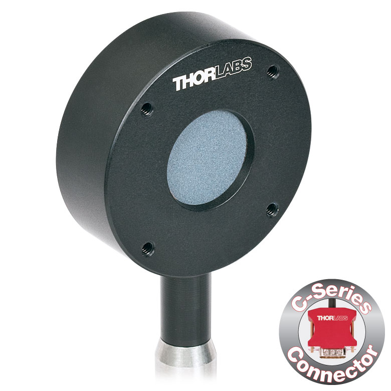 |
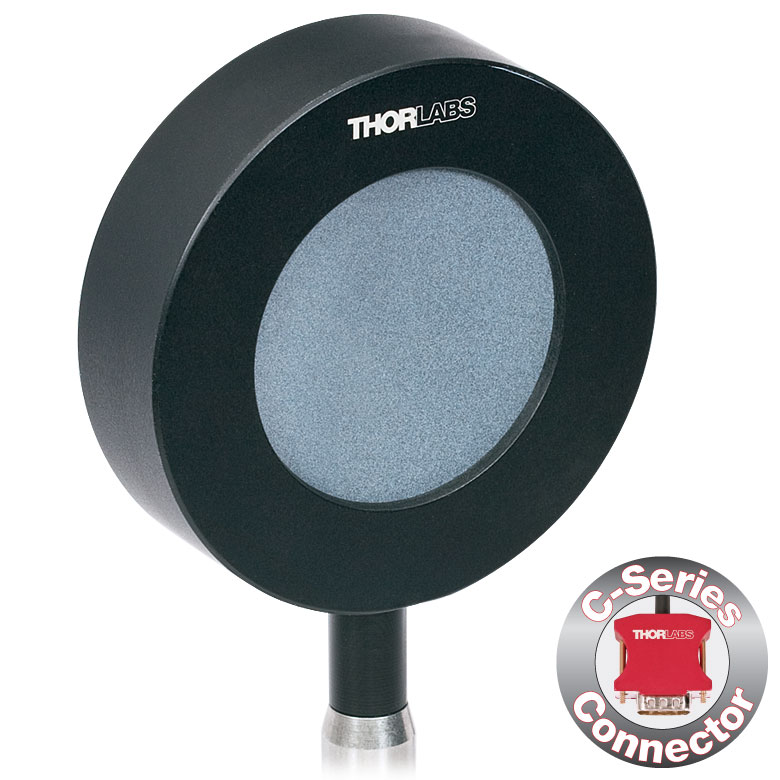 |
| Input Aperture Size | Ø20 mm | Ø45 mm |
| Wavelength Range | 185 nm - 25 µm | |
| Energy Range | 500 µJ - 3 J | 1 mJ - 15 J |
| Max Repetition Rateb | 30 Hz | 30 Hz |
| Max Power Density (Pulse Width) |
65 MW/cm2 (7 ns Pulse @ 355 nm) |
|
| Max Pulse Energy Density (Pulse Width) |
0.45 J/cm2 (7 ns Pulse @ 355 nm) |
|
| Coating (Click for Plot) | Ceramic | |
| Resolution | 25 µJ | 50 µJ |
| Linearity | ±1% | |
| Measurement Uncertainty | ±5% @ 185 nm - 25 µm | |
| Housing Dimensions | Ø50 mm x 18 mm | Ø75 mm x 21 mm |
| Active Detector Area | 314.2 mm2 | 1590.4 mm2 |
| Cable Length | 1.5 m (60") | |
| Post Mounting | 8-32 Mounting Thread, 8-32 and M4 Insulating Adapters Included | |
| Cage Mounting | Four 4-40 Threaded Holes for 30 mm Cage Systems | N/A |
| Compatible Consoles | PM100D2, PM100D3, PM400, and PM5020 | |
| Compatible Interfaces | PM103, PM103A, PM103E, PM103U, and PM100USB | |
- For Measurements of Repetition Rates Up to 10 kHz
- Two Coating Options:
- Black Broadband Coating with Flat Response from 185 nm to 25 µm
- Metal Coating for 185 nm to 2.5 µm to Support Detecting Repetition Rates Up to 10 kHz
- Ø8 mm or Ø12 mm Sensor Areas
- BNC Connector for Oscilloscope Use
- Includes C-Series Connector Adapter for Use with Compatible Thorlabs' Consoles (See Table 743A or the Console Selection Tab)
- See the Full Web Presentation for More Information
These Fast Pyroelectric Sensors are designed to measure pulsed coherent and incoherent sources with high repetition rates up to 10 kHz. Pyroelectric sensors are not suited for CW measurements, as they convert energy from light pulses into voltage pulses. The ES3xxC sensors have a black broadband that provides a flat response from 185 nm to 25 µm, and, depending on the sensor size, can support measurements of repetition rates up to 1 kHz. The metal-coated E4xxC sensors can detect repetition rates up to 10 kHz, depending on the sensor size, over a more limited wavelength range of 185 nm to 2.5 µm. Ø8 mm or Ø12 mm sensor areas are available, and each input aperture has external SM1 (1.035"-40) threads for compatibility with our SM1-threaded lens tubes. These energy sensors have BNC connectors for connection to an oscilloscope with a 1 MΩ load input resistance; using these sensors with a different load resistance may lead to reduced speed. A BNC to C-Series adapter containing NIST- and PTB-traceable calibration data is also included with each sensor.
Thorlabs offers a recalibration service for these energy sensors, which can be ordered below (see Item # CAL-THPY).
| Table 743A Specifications | ||||
|---|---|---|---|---|
| Item #a | ES308C | ES312C | ES408C | ES412C |
| Sensor Image (Click the Image to Enlarge) |
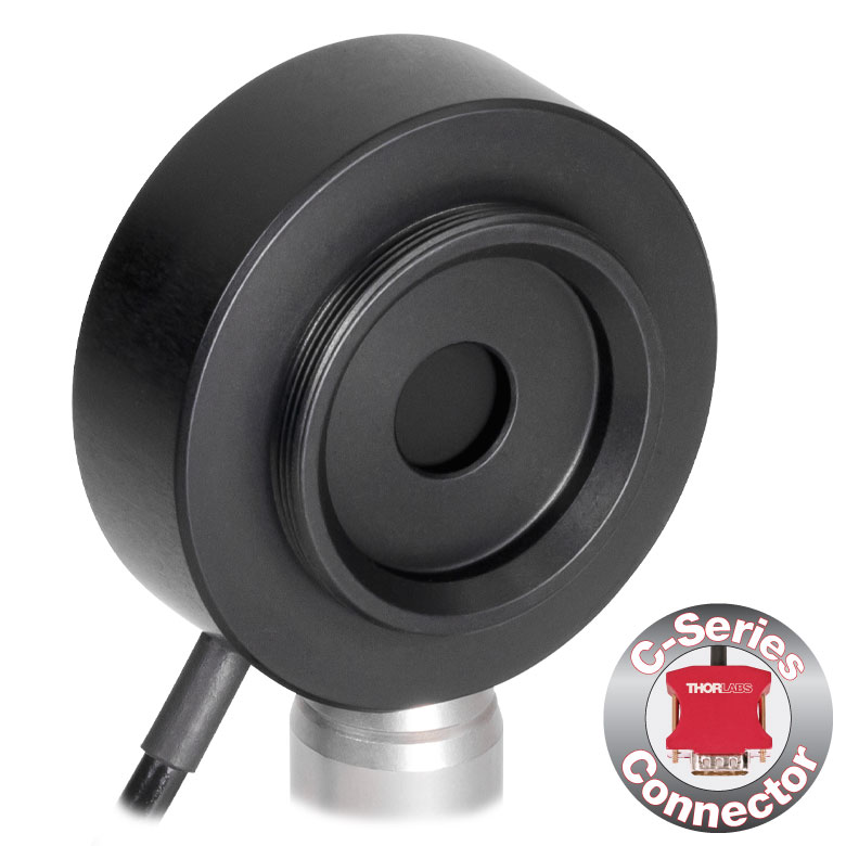 |
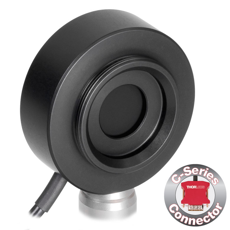 |
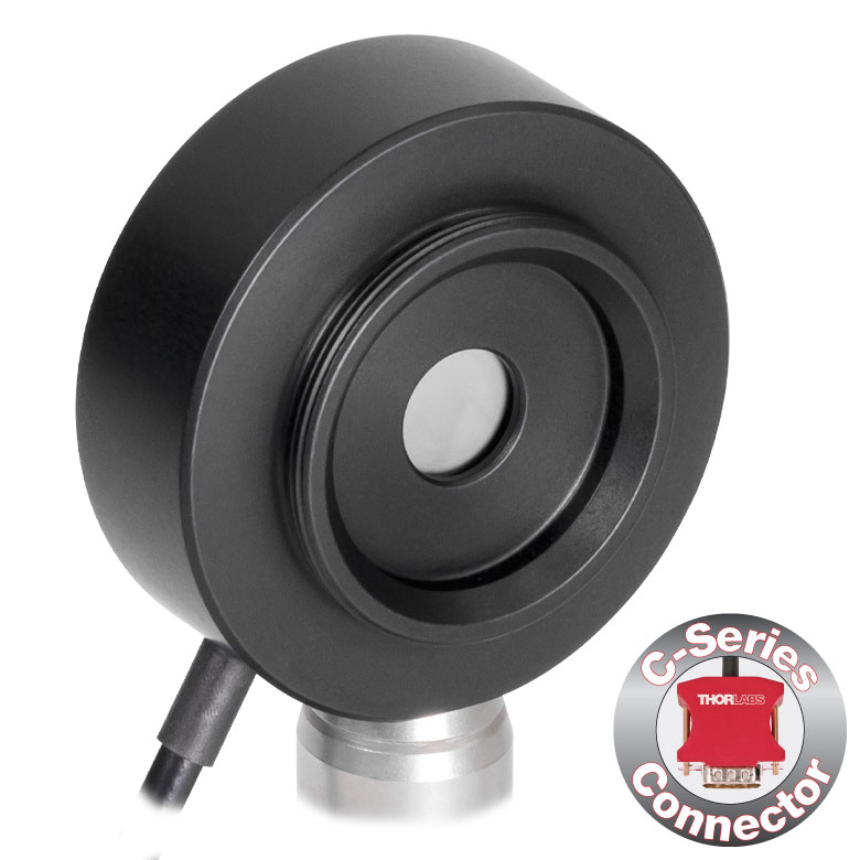 |
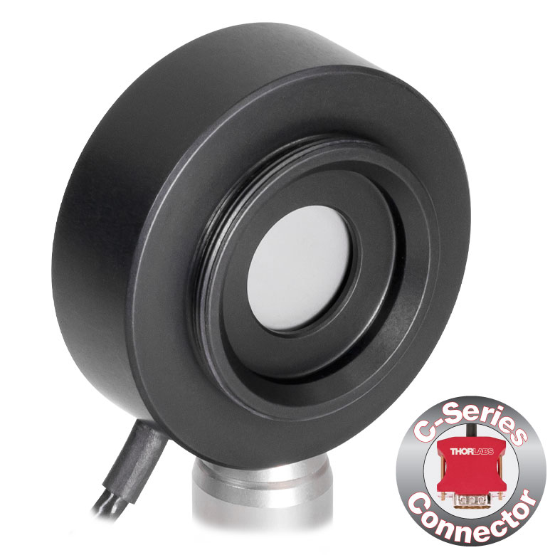 |
| Input Aperture Size | Ø8 mm | Ø12 mm | Ø8 mm | Ø12 mm |
| Wavelength Range | 185 nm - 25 µm | 185 nm - 2.5 µm | ||
| Energy Range | 500 µJ - 1 J | 100 µJ - 1 J | 100 µJ - 1 J | 50 µJ - 500 mJ |
| Max Repetition Rateb | 1 kHz | 250 Hz | 10 kHz | 2 kHz |
| Max Power Density (Pulse Width) |
8 MW/cm2 (10 ns Pulse) |
5 MW/cm2 (10 ns Pulse) |
||
| Max Pulse Energy Density (Pulse Width) |
80 mJ/cm2 (10 ns Pulse) |
50 mJ/cm2 (10 ns Pulse) |
||
| Coating (Click for Plot) | Black Broadband | Metal | ||
| Resolution | 5 µJ | 1 µJ | 1 µJ | 1 µJ |
| Linearity | ±1% | |||
| Measurement Uncertainty | ±5% @ 185 nm - 25 µm | ±5% @ 185 nm - 2.5 µm | ||
| Housing Dimensionsc | Ø38 mm x 15 mm | Ø38 mm x 15 mm | Ø38 mm x 15 mm | Ø38 mm x 15 mm |
| Active Detector Area | 50.3 mm2 | 113.1 mm2 | 50.3 mm2 | 113.1 mm2 |
| Cable Length | 1.5 m (60") | |||
| Post Mounting | 8-32 and M4 Combi Mounting Thread | |||
| Aperture Thread | External SM1 (1.035"-40) Thread Thread Depth: 3.0 mm (0.12") |
|||
| Compatible Consoles | PM100D2, PM100D3, PM400, and PM5020 | PM100D2, PM100D3, and PM5020 | PM100D2, PM100D3, PM400, and PM5020 | |
| Compatible Interfaces | PM103, PM103A, PM103E, PM103U, and PM100USB | PM103, PM103A, PM103E, and PM103U | PM103, PM103A, PM103E, PM103U, and PM100USB | |
| Table 236A Compatibility | |
|---|---|
| Calibration Service Item # | Compatible Sensors |
| CAL-UVPD | S120VC |
| CAL-PD | S116C, S120C, S121C, S170C, S140C, S142C, S142CL, S150C, S151C, PM16-120, PM16 |
| CAL-UVPD2 | S130VC |
| CAL-PD2 | S130C, PM16-130, PM160 |
| CAL-NS | NS170C |
| CAL-IRPD | S122C, S144C, S145C, S145CL, S146C, S154C, S155C, PM16-122, PM16-144 |
| CAL-IRPD2 | S132C |
| CAL-MIRPD | S148C, S180C |
Thorlabs offers traceable recalibration services for our photodiode optical power sensors. To ensure accurate measurements, we recommend recalibrating the sensors annually. The manufacturer calibration of a power sensor includes recalibration of a single-channel console or interface at no additional cost; this is unavailable for the accredited calibration option. If you wish to calibrate one or more sensors with a dual-channel console, each sensor and console calibration service will need to be purchased individually. For more details on these recalibration services, please click the Documents (![]() ) icons below.
) icons below.
Refer to Table 236A for the appropriate calibration service Item # that corresponds to your power sensor.
Requesting a Calibration
Thorlabs provides two options for requesting a calibration:
- Complete the Returns Material Authorization (RMA) form. When completing the RMA form, please enter your name, contact information, the Part #, and the Serial # of each item being returned for calibration; in the Reason for Return field, select "I would like an item to be calibrated." In the Further Details field, please indicate "Manufacturer Calibration" or the desired calibration part number below in order to differentiate from the ISO 17025 accredited calibration option. Once the form has been submitted, a member of our RMA team will reach out to provide an RMA Number, return instructions, and to verify billing and payment information.
- Select the appropriate sensor calibration Item # below, enter the Part # and Serial # of the sensor that requires recalibration, and then Add to Cart. If you would like a console calibrated with your sensor, repeat this process for Item # CAL-PM1 or CAL-PM2 below, entering the console Item # and Serial #. A member of our RMA team will reach out to coordinate the return of the item(s) for calibration. Note that each console calibration Item # represents the cost of calibrating a console alone; if requesting a single-channel console calibration with a sensor calibration, the appropriate discount will be applied when your request is processed. Should you have other items in your cart, note that the calibration request will be split off from your order for RMA processing.
Please Note: To ensure your item being returned for calibration is routed appropriately once it arrives at our facility, please do not ship it prior to being provided an RMA Number and return instructions by a member of our team.
| Table 791A Compatibility | |
|---|---|
| Calibration Service Item # | Compatible Sensors |
| CAL-UVPDD | S120VC |
| CAL-PDD | S116C, S120C, S121C, S170C, S140C, S142C, S142CL, S150C, S151C, PM16-120, PM16 |
| CAL-UVPD2D | S130VC |
| CAL-PD2D | S130C, PM16-130, PM160 |
| CAL-IRPDD | S122C, S144C, S145C, S145CL, S146C, S154C, S155C, PM16-122, PM16-144 |
| CAL-IRPD2D | S132C |
| CAL-MIRPDD | S148C |
Thorlabs offers ISO 17025 accredited recalibration services for our photodiode optical power sensors. If you wish to calibrate one or more sensors with a console, each sensor and console calibration service will need to be purchased individually. ISO 17025 accredited calibrations are performed in accordance with DIN EN ISO/IEC 17025:2018. Thorlabs GmbH's calibration laboratory is accredited by the German Accreditation Body (DAkkS), the national accreditation authority of the Federal Republic of Germany. The scope of services is described here in English or German. For more details on these recalibration services, please see the Recalibration tab or click the Documents (![]() ) icons below.
) icons below.
Refer to Table 791A for the appropriate calibration service Item # that corresponds to your power sensor.
Requesting a Calibration
Thorlabs provides two options for requesting a calibration:
- Complete the Returns Material Authorization (RMA) form. When completing the RMA form, please enter your name, contact information, the Part #, and the Serial # of each item being returned for calibration; in the Reason for Return field, select "I would like an item to be calibrated." In the Further Details field, please indicate "ISO 17025 Accredited Calibration" or the desired calibration part number below in order to differentiate from the manufacturer calibration option. Once the form has been submitted, a member of our RMA team will reach out to provide an RMA Number, return instructions, and to verify billing and payment information.
- Select the appropriate sensor calibration Item # below, enter the Part # and Serial # of the sensor that requires recalibration, and then Add to Cart. If you would like a console calibrated with your sensor, repeat this process for Item # CAL-PM1, CAL-PM1D, CAL-PM2, or CAL-PM2D below, entering the console Item # and Serial #. A member of our RMA team will reach out to coordinate the return of the item(s) for calibration. Note that each console calibration Item # represents the cost of calibrating a console alone; if requesting a single-channel console calibration with a sensor calibration, the appropriate discount will be applied when your request is processed. Should you have other items in your cart, note that the calibration request will be split off from your order for RMA processing.
Please Note: To ensure your item being returned for calibration is routed appropriately once it arrives at our facility, please do not ship it prior to being provided an RMA Number and return instructions by a member of our team.
| Table 317A Compatibility | |
|---|---|
| Sensor Type | Sensor Item #s |
| Thermal Power | S175C, S302Ca, S305Ca, S310Ca, S314Ca,S322C, S350C, S370C, S401C, S405C, S415C, S425C, S425C-L, S470C, PM160T, PM160T-HP, PM16-401, PM16-405 |
| Pyroelectric Energy | ES111C, ES120C, ES145C, ES220C, ES245C, ES308C, ES312C, ES408C, ES412C |
Thorlabs offers recalibration services for our Thermal Power and Pyroelectric Energy Sensors. To ensure accurate measurements, we recommend recalibrating the sensors annually. Recalibration of a single-channel power and/or energy meter console or interface is included with the recalibration of a sensor at no additional cost. If you wish to calibrate one or more sensors with a dual-channel console, each sensor and console calibration service will need to be purchased individually.
Please note that the CAL-THPY recalibration service cannot be used for our Thermal Position & Power Sensors; recalibration for these sensors can be requested by contacting Tech Support. Table 317A lists the sensors for which the CAL-THPY recalibration service is available.
Requesting a Calibration
Thorlabs provides two options for requesting a calibration:
- Complete the Returns Material Authorization (RMA) form. When completing the RMA form, please enter your name, contact information, the Part #s, and the Serial #s of all sensors or consoles being returned for calibration; in the Reason for Return field, select "I would like an item to be calibrated." All other fields are optional. Once the form has been submitted, a member of our RMA team will reach out to provide an RMA Number, return instructions, and to verify billing and payment information.
- Enter the Part # and Serial # of the item that requires recalibration below and then Add to Cart. If you would like a console calibrated with your sensor, repeat this process for Item # CAL-PM1 or CAL-PM2 below, entering the console Item # and Serial #. A member of our RMA team will reach out to coordinate the return of the item(s) for calibration. Note that each console calibration Item # represents the cost of calibrating a console alone; if requesting a single-channel console calibration with a sensor calibration, the appropriate discount will be applied when your request is processed. Should you have other items in your cart, note that the calibration request will be split off from your order for RMA processing.
Please Note: To ensure your item being returned for calibration is routed appropriately once it arrives at our facility, please do not ship it prior to being provided an RMA Number and return instructions by a member of our team. Pyroelectric energy sensors returned for recalibration or servicing must include the separate BNC to DB9 adapter, which contains the sensor EEPROM.
| Table 719A Compatibility | |
|---|---|
| Calibration Service Item # | Compatible Consoles & Interfaces |
| Single-Channel | |
| CAL-PM1 | PM100D2, PM100D3, PM100A, PM400, PM100USB, PM100Da PM101 Series, PM102 Series, PM103 Series |
| Dual-Channel | |
| CAL-PM2 | PM5020 and PM320Ea |
These traceable recalibration services are for the power and/or energy meter electronics of our consoles and interfaces. To ensure accurate measurements, we recommend recalibrating annually. The manufacturer calibration of a power sensor includes recalibration of a single-channel console or interface at no additional cost; this is unavailable for the accredited calibration option. If you wish to calibrate one or more sensors with a dual-channel console, each sensor and console calibration service will need to be purchased individually. For more details on these recalibration services, please click the Documents (![]() ) icons below.
) icons below.
Table 719A lists the power and/or energy meter consoles and interfaces that can be calibrated using the CAL-PM1 and CAL-PM2 recalibration services.
Requesting a Calibration
Thorlabs provides two options for requesting a calibration:
- Complete the Returns Material Authorization (RMA) form. When completing the RMA form, please enter your name, contact information, the Part #, and the Serial # of each item being returned for calibration; in the Reason for Return field, select "I would like an item to be calibrated." In the Further Details field, please indicate "Manufacturer Calibration" or the desired calibration part number below in order to differentiate from the ISO 17025 accredited calibration option. Once the form has been submitted, a member of our RMA team will reach out to provide an RMA Number, return instructions, and to verify billing and payment information.
- Select the appropriate Item # below, enter the Part # and Serial # of the item that requires recalibration, and then Add to Cart. If you would like to calibrate one or more sensors with your console, repeat this process for the appropriate sensor recalibration service above, entering the console Item # and Serial #. A member of our RMA team will reach out to coordinate return of the item(s) for calibration. Note that each console calibration Item # represents the cost of calibrating a console alone; if requesting a single-channel console calibration with a sensor calibration, the appropriate discount will be applied when your request is processed. Should you have other items in your cart, note that the calibration request will be split off from your order for RMA processing.
Please Note: To ensure your item being returned for calibration is routed appropriately once it arrives at our facility, please do not ship it prior to being provided an RMA Number and return instructions by a member of our team.
| Table 792A Compatibility | |
|---|---|
| Calibration Service Item # | Compatible Consoles & Interfaces |
| Single-Channel | |
| CAL-PM1D | PM100D2, PM100D3, PM100A, PM400, PM100USB, PM100Da PM101 Series, PM102 Series, PM103 Series |
| Dual-Channel | |
| CAL-PM2D | PM5020 |
These ISO 17025 accredited recalibration services are for the power and/or energy meter electronics of our consoles and interfaces. If you wish to calibrate one or more sensors with a console, each sensor and console calibration service will need to be purchased individually. ISO 17025 accredited calibrations are performed in accordance with DIN EN ISO/IEC 17025:2018. Thorlabs GmbH's calibration laboratory is accredited by the German Accreditation Body (DAkkS), the national accreditation authority of the Federal Republic of Germany. The scope of services is described here in English or German. For more details on these recalibration services, please see the Recalibration tab or click the Documents (![]() ) icons below.
) icons below.
Table 792A lists the power and/or energy meter consoles and interfaces that can be calibrated using the CAL-PM1D and CAL-PM2D recalibration services.
Requesting a Calibration
Thorlabs provides two options for requesting a calibration:
- Complete the Returns Material Authorization (RMA) form. When completing the RMA form, please enter your name, contact information, the Part #, and the Serial # of each item being returned for calibration; in the Reason for Return field, select "I would like an item to be calibrated." In the Further Details field, please indicate "ISO 17025 Accredited Calibration" or the desired calibration part number below in order to differentiate from the manufacturer calibration option. Once the form has been submitted, a member of our RMA team will reach out to provide an RMA Number, return instructions, and to verify billing and payment information.
- Select the appropriate Item # below, enter the Part # and Serial # of the item that requires recalibration, and then Add to Cart. If you would like to calibrate one or more sensors with your console, repeat this process for the appropriate sensor recalibration service above, entering the console Item # and Serial #. A member of our RMA team will reach out to coordinate return of the item(s) for calibration. Note that each console calibration Item # represents the cost of calibrating a console alone; if requesting a single-channel console calibration with a sensor calibration, the appropriate discount will be applied when your request is processed. Should you have other items in your cart, note that the calibration request will be split off from your order for RMA processing.
Please Note: To ensure your item being returned for calibration is routed appropriately once it arrives at our facility, please do not ship it prior to being provided an RMA Number and return instructions by a member of our team.