 Products Home
Optical Power Meter Kits
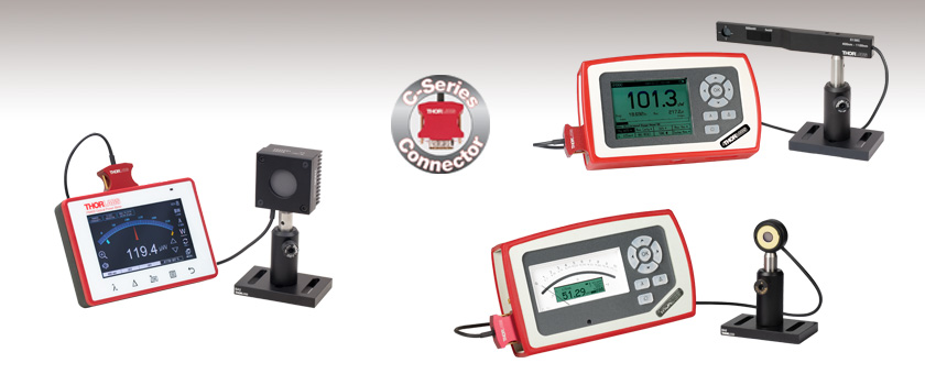
- Kits Include Console, Sensor, and Post Assembly
- Digital or Analog Console
- Wavelengths from 190 nm to 20 µm
- Powers from 500 pW to 10 W
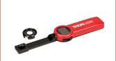
PM400K5
Digital Console with Thermal Sensor
PM130D
Digital Console with Slim Photodiode Sensor
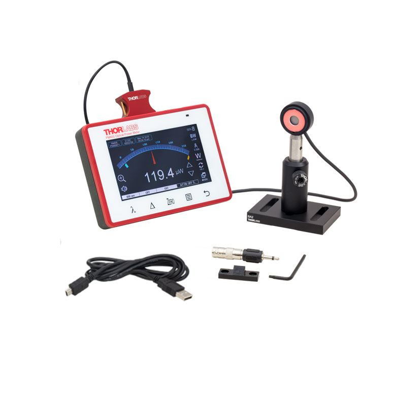
PM120VA
Analog Console with Photodiode Sensor


Please Wait
| Power Meter Kit Specifications | ||||
|---|---|---|---|---|
| Item # | Power Range | Wavelength Range | Sensor Type | Console Type |
| PM120VA | 50 nW - 50 mW | 200 - 1100 nm | Si (S120VC) | Analog (PM100A) |
| PM120D | 50 nW - 50 mW | 400 - 1100 nm | Si (S120C) | Digital (PM100D) |
| PM400K1 | 50 nW - 50 mW | 400 - 1100 nm | Si (S120C) | Touchscreen Digital (PM400) |
| PM121D | 500 nW - 500 mW | 400 - 1100 nm | Si (S121C) | Digital (PM100D) |
| PM400K2 | 500 nW - 500 mW | 400 - 1100 nm | Si (S121C) | Touchscreen Digital (PM400) |
| PM130D | 500 pW - 500 mWa | 400 - 1100 nm | Slim Si (S130C) | Digital (PM100D) |
| PM400K3 | 500 pW - 500 mWa | 400 - 1100 nm | Slim Si (S130C) | Touchscreen Digital (PM400) |
| PM122D | 50 nW - 40 mW | 700 - 1800 nm | Ge (S122C) | Digital (PM100D) |
| PM400K4 | 50 nW - 40 mW | 700 - 1800 nm | Ge (S122C) | Touchscreen Digital (PM400) |
| PM125D | 2 mW - 10 W | 0.19 - 20 µm | Thermal (S425C) | Digital (PM100D) |
| PM400K5 | 2 mW - 10 W | 0.19 - 20 µm | Thermal (S425C) | Touchscreen Digital (PM400) |
| Power Meter Selection Guide |
|---|
| Sensors |
| Photodiode Power Sensors |
| Thermal Power Sensors |
| Thermal Position & Power Sensors |
| Pyroelectric Energy Sensors |
| Power Meter Consoles |
| Digital Handheld Console |
| Analog Handheld Console |
| Touchscreen Handheld Console |
| Dual-Channel Benchtop Console |
| Complete Power Meters |
| Power Meter Bundles |
| Wireless Power Meters with Sensors |
| Compact USB Power Meters |
| Field Power Meters for Terminated Fibers |
| USB Interfaces, External Readout |
Features
- Includes Console, Sensor, and Mounting Components
- Consoles Compatible with C-Series Sensors
- Large, Easy-to-Read Digital or Analog Display
- USB 2.0 Port for Control via PC with Optical Power Monitor Software (See Software Tab)
- Rechargeable Battery
- 3.5 mm Jack or SMA Output (0 to 2 V) on Consoles for Monitoring Signal
- Recalibration Services Available
Our optical power meter kits consist of a console, a C-series photodiode or thermal power sensor, and a post mounting assembly. Except for the PM120VA, which includes the PM100A analog power meter console, the sensor in each kit is paired with either a PM100D digital or PM400 touchscreen digital power meter console. For a full list of available kits, see the table to the right.
All three consoles have a USB 2.0 connection that allows them to be controlled remotely using a PC with the Optical Power Meter software package installed (see the Software tab for details).
PM100A Analog Console
Suitable for both absolute and relative power measurements, the PM100A analog power meter console features an analog needle display and a supplemental LCD screen. The analog needle is ideal for relative power measurements and for watching small power fluctuations. The PM100A is compatible with all C-Series photodiode sensors and thermal sensors; it is not compatible with our pyroelectric energy sensors. The PM120VA power meter kit includes the PM100A console and power cables, an S120VC sensor, and a USB flash drive with the software package preloaded. For more information on the PM100A analog console features, see the Specs and Display tabs above or visit the full web presentation.
PM100D Digital Console
The PM100D digital power and energy meter console features a menu-driven control panel, 4" backlit display, and SD card slot for storing data. Measurements screens include a numeric readout useful for standard power and energy readings, a simulated analog needle, graphs of power measurements over time, and a statistics view. Additionally, the PM100D console has a tuning mode that provides audio feedback for use when the detector is not within visual range. See the PM100D Display tab for more information. The console is compatible with all our C-Series sensors for power or energy measurements, including our pyroelectric energy sensors, and includes a USB flash drive with the software package preloaded. For more information on the PM100D digital console features, see the Specs and Display tabs above or visit the full web presentation.
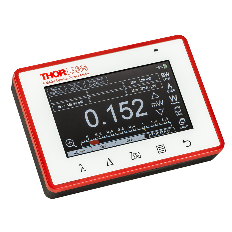
PM400 Touchscreen Digital Console
The PM400 touchscreen digital power and energy meter console features a 4.3" display with multi-touch technology. Capacitive buttons on the front of the unit enable fast access to set the source wavelength or spectrum, a delta mode that shows the change in power from a user-selected set point, the zeroing function, and device main menu. In addition to pre-programming source wavelengths or spectra for calibrating measurements, users can enter and save up to twelve attenuation values or data files to correct for effects that external devices (such as filters or beamsplitters) may have on the power measurement.
A 14-pin auxiliary input allows users to connect their own humidity and temperature sensors as well as access four programmable I/O ports for controlling shutters, interlock devices, laser warning lights, and other common lab devices (see the Pin Diagrams tab for pin descriptions). Alternatively, a 2.5 mm stereo (3P) jack accepts the TSP-TH thermistor temperature probe. Like the PM100D, this console is compatible with all our C-Series sensors. For more information on the PM400 touchscreen digital console features, see the Specs and Display tabs above or visit the full web presentation.
Additional Power Meter and Sensor Options
The power meter consoles and sensors in these kits can also be purchased individually. Additionally, Thorlabs offers self-contained wireless power meters, designed for both handheld operation and remote control via Bluetooth or USB, and compact USB power meters, designed to be operated via software control on a PC.
Recalibration Service
Recalibration services are available for our photodiode and thermal power meter sensors and consoles. We recommend recalibrating your Thorlabs sensor and console as a pair; however, each may be recalibrated individually. To order this service for your sensor or console, scroll to the bottom of the page and select the appropriate Item # that corresponds to your sensor or console. Recalibration of a single-channel console is included with the recalibration of a sensor at no additional cost.
Click here for the complete PM100A product presentation.
| PM100A Specifications | |
|---|---|
| Photodiode Sensor Input (Current) | |
| Measurement Ranges | 6 Decades; 50 nA - 5 mA |
| Units | W |
| Accuracy | ±0.2% of Full Scale (5 µA - 5 mA) ±0.5% of Full Scale (50 nA) ±3% Full Scale Analog Meter |
| Bandwidth | DC to 100 kHz, Dependent on Sensor and Settings |
| Analog Output | |
| Connector | SMA |
| Voltage Range | 0 - 2 V |
| Bandwidth | Up to 100 kHz, Dependent on Sensor and Settings |
| Accuracy | ±3% |
| General | |
| Sensor Input | Female DB9 for C-Series Connectors |
| Display | Analog Needle with 132 x 32 pixel LCD Readout |
| Display Update Rate | 20 Hz |
| Display Screens | Numerical, Relative Measurements, Tuning, Statistics, Mechanical Analog Needle |
| Memory Card | N/A |
| A/D Converter | 16 bit |
| Computer Connectivity | USB 2.0, Mini USB |
| Battery | Li-Polymer 3.7 V, 1300 mAh; up to 8 hrs of Operation |
| Dimensions | 7.2" x 4.3" x 1.6" (183 mm x 109 mm x 40 mm) |
| Operating / Storage Temp | 0 to 40 °C / -40 to 70 °C |
| Mounting | Kickstand, 1/4"-20 Mounting Hole |
Click here for the complete PM100D product presentation.
| PM100D Specifications | |
|---|---|
| Photodiode Sensor Input (Current) | |
| Measurement Ranges | 6 Decades; 50 nA - 5 mA |
| Units | W, dBm, W/cm2, A |
| Accuracy | ±0.2% of Full Scale (5 µA - 5 mA) ±0.5% of Full Scale (50 - 500 nA) |
| Bandwidth | DC to 100 kHz, Dependent on Sensor and Settings |
| Thermopile Sensor Input (Voltage) | |
| Measurement Ranges | 4 Decades; 1 mV - 1 V |
| Units | W, dBm, W/cm2, V |
| Accuracy | ±0.5% of Full Scale (10 mV - 1 V) ±1% of Full Scale (1 mV) |
| Bandwidth | DC to 10 Hz, Dependent on Sensor and Settings |
| Time Constant Correction | 1 - 30 s |
| Analog Output | |
| Connector | SMA |
| Voltage Range | 0 - 2 V |
| Bandwidth | Up to 100 kHz, Dependent on Sensor and Settings |
| Accuracy | ±3% |
| General | |
| Sensor Input | Female DB9 for C-Series Connectors |
| Display | 3.2" x 2.4" (81.4 mm x 61 mm), 320 x 240 pixels |
| Display Update Rate | 20 Hz |
| Display Screens | Numerical, Bar Graph, Trend Graph, Statistics, Simulated Analog Needle |
| Memory Card | SD, 1 GB |
| A/D Converter | 16 bit |
| Computer Connectivity | USB 2.0, Mini USB |
| Battery | Li-Polymer 3.7 V, 1300 mAh; up to 8 hrs of Operation |
| Dimensions | 7.2" x 4.3" x 1.6" (183 mm x 109 mm x 40 mm) |
| Operating / Storage Temp | 0 to 40 °C / -40 to 70 °C |
| Mounting | Kickstand, 1/4"-20 Mounting Hole |
Click here for the complete PM400 product presentation.
| Specifications | |
|---|---|
| Compatible Detectors | Thorlabs' C-Series Photodiode, Thermal, and Pyroelectric Sensors Photodiodes up to 5 mA, Thermopiles up to 1 V, and Pyroelectric Detectors up to 100 V |
| Display | |
| Type | 4.3" TFT, WQVGA, 400 x 272 Pixels, 16 Bit Color |
| Viewing Area | 95 mm x 54 mm |
| Update Rate (Max) | 10 Hz Numerical, 25 Hz Analog Simulation |
| Format | Numerical, Bar Graph, Trend Graph, Statistics, and Simulated Analog Needle |
| Backlight | LED, Adjustable |
| Features | Projected Capacitive Touchscreen and Buttons, Support Stand, Rubberized Outside, 2 x M3 Threaded Inserts for Mounting on Back Side |
| Analog Output | |
| Connector | 3.5 mm Mono Audio (2P) Jack, Adapter to BNC Included |
| Signal | Amplified Input Signal - Not Corrected |
| Voltage Range | 0 to 2 V |
| Accuracy | ±3% |
| Bandwidth | Up to 100 kHz, Dependent on Sensor and Settings |
| Auxiliary Input/Output | |
| Connector | 2 x 7 Pins, 0.1" Socket, Top Side |
| Function | 4 x GPIO 2 x 10 bit ADC for External Temperature, Relative Humidity Sensor +3.3 V, +/- 2.5 V (100 mA Max) |
| Temperature Sensor Internal to C-Series Optical Sensora | |
| Temperature Sensor Type | Thermistor |
| Temperature Measurement Range | -10 °C to 80 °C |
| External Temperature Sensor | |
| Supported Temperature Sensor | Thermistor NTC 0.1 - 100 kΩ, B-Value 1000 - 9999 K |
| Temperature Measurement Range | -10 °C to 80 °C (with TSP-TH) |
| Connector | 2.5 mm Stereo Audio (3P) Jack |
| Sound | |
| Type | Internal Speaker |
| Function | Laser Tuning Support, Console Function Support |
| Memory | |
| Type | NAND Flash |
| Size | 4 GB |
| Interfaces | |
| Type | USB 2.0 |
| Connector | Mini-B USB |
| Power Management | |
| Battery | LiPo 3.7 V 2600 mAh |
| Charger | Built In; Charging Current: 0.5 / 1 A |
| Power Connector | Mini USB |
| General | |
| Operating Temperature Rangeb | 0 to 40 °C |
| Storage Temperature Range | -40 to 70 °C |
| Dimensions | 136 mm x 96 mm x 29 mm |
| Weight | 0.35 kg |
| PM100A Display | |
|---|---|
| Standard Absolute Measurements | Relative Measurements |
 |  |
| This display shows the current absolute power values on both the mechanical needle and the LCD display. | Shows positive or negative power deviation from an initially zeroed position (needle in middle position). The offset and the absolute power value will be displayed in two sub displays in negative presentation. |
| Power Tuning with Sound Support | Statistics Screen |
 |  |
| This display shows the maximum reached power level. The level can be reset to the actual power level. | A display showing the current, min, max, and average power. All items can be reset to restart data sampling. |
| Wavelength Setting | |
 | |
| Configuration screen to set the wavelength of the incident beam. Easy switching between 9 user preconfigurable wavelengths. | |
| PM100D Display | |||
|---|---|---|---|
| Numeric Screen (Power Mode) | Numeric Screen (Energy Mode) | ||
 |
This display combines a clear, numerical 4-digit read out of the optical power, a bar graph function with zooming capabilities, and configurable sub displays. |  |
A display with the same option as on the left for optical energy read outs. |
| Trend Graph (Power Mode) | Needle Tuning (Power Mode) | ||
 |
For laser tuning and beam alignment to visualize changes and trends together with an additional 4-digit numerical value of the absolute power. |  |
A display imitating an analog needle together with an additional 4-digit numerical value for laser tuning tasks. A special feature is a resettable max hold indicator and a shiftable tuning sound. |
| Pulse Chart (Energy Mode) | Statistics Screen (Power Mode) | ||
 |
Like the Trend Graph (Power Mode), this shows changes and trends together with an additional 4-digit numerical value of the absolute energy of incident beam pulses. |  |
The statistics display shows the actual, minimum, maximum and mean value in linear and logarithmic representation; further the standard deviation, the max/min ratio, the number of samples and the elapsed time. |
Common Display Elements
- Header line with sensor information, date/time, and battery state
- Status line with warning annunciators
- Bar graph and configurable left and right sub display areas to display a minimum and a maximum value or a ratio of both values (numerical screen only)
- Tool tip text above the menu
- Easily accessible menu via buttons
Click to Enlarge
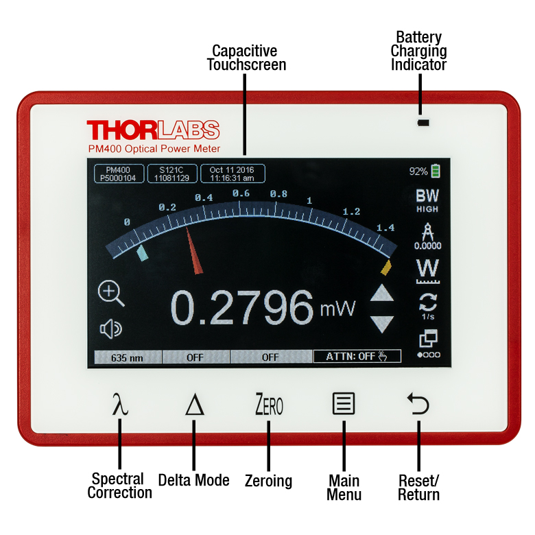
The Front Panel of the Touchscreen Power Meter Console
Touchscreen Power Meter Console Front Panel
Thorlabs' PM400 Power Meter Console features a front panel with several key elements, as shown in the photo to the right. The projected capacitive touchscreen and buttons are sensitive enough to allow smooth operation even when the user wears cotton, latex, or nitrile gloves, but durable enough to be cleaned with standard screen cleaning solvents.
- Capacitive Touchscreen: The capacitive touchscreen allows the user to control the console functions with finger taps and swipes. Features include numerical displays of power and energy measurements, logging of long-term measurements, settings for a calibration wavelength or a preset attenuation value, and temperature monitoring. The user can switch measurement views by swiping one finger over the screen to the left or right, or by tapping the window icon in the lower right corner of the screen. More details on the measurement options are provided below.
- Spectral Correction Button: This button opens a screen where the user can quickly select or save up to 12 measurement wavelengths. The PM400 will use this wavelength setting in conjunction with the calibration data recorded in the connector of Thorlabs' power and energy sensors in order to provide a calibrated optical power or energy reading. The selected wavelength is displayed above the button.
- Delta Mode: In delta mode, the console will display the power or energy relative to a user selected setpoint. Pressing this button saves the current power or energy reading as the reference value, and subsequent measurements will be displayed as the difference between the actual value and the reference. The reference value is displayed above this button when Delta Mode is active.
- Zeroing: Quickly set the current power or energy value as the zero point for subsequent measurements. The measured power or energy when the console is zeroed will be displayed above the Zero button.
- Main Menu: This button provides quick access to the main menu. From here, the user can access a submenu to set the parameters for long-term power measurements, device settings, the file manager, sensor info, and the laser calculator. Details are provided below.
Additional Features
In addition to allowing users to select different measurement modes and settings, the PM400 incorporates other features to allow users to customize the interface.
- Language Settings: English, French, German, and Chinese can be selected.
- Display Brightness and Contrast: In addition to adjusting these settings, the user can choose whether to have the display show white text on a black background, or black text on a white background.
- Laser Tuning Sound: The console plays an audible tone to aid in identifying when peak power is achieved while tuning a laser. The console will beep repeatedly, with the frequency of the beep increasing as the measured power increases.
- Programmable I/O Ports: The PM400 features four programmable I/O ports for controlling shutters, interlocks, laser warning lights, etc.
The Touchscreen Display
The screenshots below provide an overview of some of the measurement views, measurement settings, functions, and calculators accessible through the touchscreen display.
Numerical Display
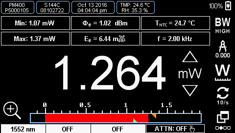
| Subpanel Display Options | ||
|---|---|---|
| Photodiode Sensors | Thermal Sensors | Pyroelectric Sensors |
| Current (IDET) | Voltage (VDET) | Voltage (VDET) |
| Power (Φe) | Power (Φe) | Energy (WDET) |
| Power in dBm (Φe) | Power in dBm (Φe) | N/A |
| Max | Max | Max |
| Min | Min | Min |
| Ratio (Max/Min) | Ratio (Max/Min) | Ratio (Max/Min) |
| Sensor Temperaturea | Sensor Temperaturea | N/A |
| Frequency | Frequency | Frequency |
| External NTC Temperature | External NTC Temperature | External NTC Temperature |
| Irradiance (Ee) | Irradiance (Ee) | Fluence (He) |
The numerical display shows a digital measurement of the power or energy with a bar graph along the bottom. The orange and blue triangles on the bar graph show the min and max values detected during the measurement. To reset the min and max values, press the reset button on the front panel. The six rectangular subpanels immediately above the power or energy measurement are configurable displays, allowing the user to select which parameters to view. The Subpanel Display Options table provides a summary of available settings for each style of detector.
Simulated Analog Needle
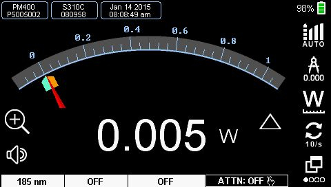
Measurements can be viewed with a simulated analog needle. The orange and blue marks are indicators for the max and min measured power, and the scale can be zoomed by a factor of 10. Icons down the side of the screen allow the user to set the bandwidth, adjust the resolution of the digital value at the bottom of the display, change units, adjust the display update rate or change screens.
Graph View
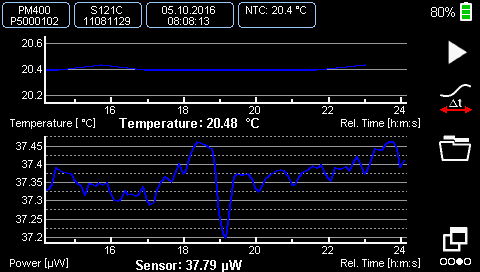
In the graph view, the user can monitor the optical power or energy of a source as it changes over time. A second, optional display can be added that shows the readout from a connected temperature sensor (the upper graph in the screenshot above). Icons on the side of the window allow the user to start and stop the measurement, scroll through the data, and open the folder where the measurement is saved.
Statistics Display
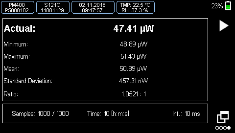
In the statistics display, the user can start a sequential measurement. The sample rate and duration can be adjusted from the Capture Settings screen, accessible from the main menu. The bottom bar of the display shows the number of measurements taken, total elapsed time since the measurements were started, and the measurement interval. The main part of the display shows statistics for the accumulated measurements, including the minimum, maximum, mean, and standard deviation.
Spectral Correction
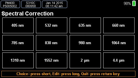
This mode can be entered by pressing the λ symbol on the front panel. The unit can store up to 12 preset spectral correction entries, editable by the user. In their simplest form, these entries can consist of a single user-entered wavelength that will be used in conjunction with the NIST-traceable calibration data from a Thorlabs' sensor to produce a calibrated power measurement. Alternatively, each entry can be a .csv file with the source spectrum that has been uploaded and saved. When a spectral correction entry is selected, the entry name will be displayed in the field above the spectral correction button.
Attenuation Correction
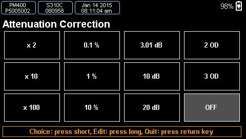
External devices within a setup, such as a filter or beamsplitter, may be needed to attenuate the signal being measured. The attenuation correction function allows the PM400 to display a power reading that accounts for these sources of attenuation. Attenuation values can be assigned as a multiplier (e.g. x2), in percent, in dB, or in OD (optical density). Alternatively, complete filter transmission curves can be uploaded and saved. Up to 12 different attenuation settings can be programmed and stored.
Main Menu
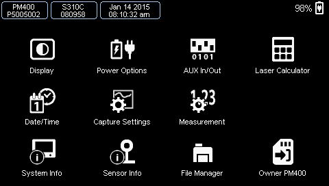
The PM400 main menu allows access to device features including the screen brightness, the menus to set the parameters for power, energy, and temperature measurements, a screen for calculating laser pulse characteristics, and a unit converter.
Capture Settings
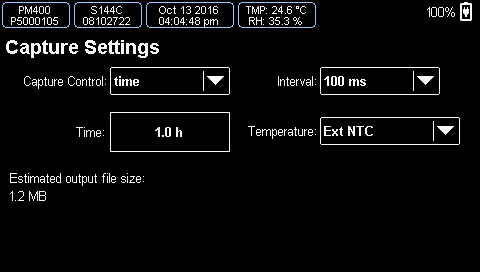
This screen allows the user to set the parameters for taking data. User-selectable settings include manual or automatic data acquisition, the exposure time, the number of samples, and the capture interval. It also allows the temperature logging parameters to be set. Once all of the settings are selected, this screen will return an estimated file size so that the user can ensure there is enough free memory on the device. In the case of manual operation (the user manually starts and stops the measurement), the estimated output file size will be the rate at which memory is used up as the data is collected.
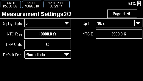
Sensor Measurement Settings
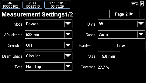
This screen allows the user to view sensor-dependent content, adjust common settings such as wavelength, attenuation, mode, etc., and enter beam parameters.
Temperature Sensor Settings
If an external temperature sensor is hooked up to the PM400, the user can adjust the parameters here.
Laser Calculator and Unit Converter
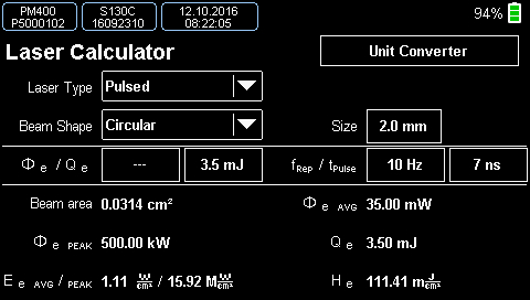
The PM400 has several calculators. The laser calculator screen allows the user to calculate laser beam parameters based on available inputs. A unit converter provides quick conversions between Watts and dBm or between wavelength, frequency, wavenumbers, and photon energy.
PM100A and PM100D Power Meter Consoles
Optical Sensor Head Input
9-Pin Female D-Sub
| Connection | ||
|---|---|---|
| Pin | PM100A | PM100D |
| 1 | +5 V (100 mA Max Current from This Pin) | |
| 2 | DO NOT USEa | |
| 3 | AGND (Analog Ground): Photodiode Ground (Anode), Thermal and Pyroelectric Sensor Ground |
|
| 4 | Photodiode Cathode | |
| 5 | Not Connected | Pyro-Electric Sensor + |
| 6 | DGND (Digital Ground) | |
| 7 | Present: Connect this Pin via a 1 kΩ to 10 kΩ Resistor to Pin 3 (AGND) to Enable a Custom Sensor |
|
| 8 | Thermal Sensor + | |
| 9 | Not Connected | |
Analog Output
0 ... 2 V,
SMA Female
Computer Connection
USB Type Mini-B
USB Type Mini-B for Remote Control and Charging,
Cable Included
PM400 Power Meter Console
Optical Sensor Head Input
9-Pin Female D-Sub
| Pin | Connection |
|---|---|
| 1 | +5 V (100 mA Max Current from This Pin) |
| 2 | DO NOT USEa |
| 3 | AGND (Analog Ground): Photodiode Ground (Anode), Thermal and Pyroelectric Sensor Ground |
| 4 | Photodiode Cathode |
| 5 | Pyroelectric Sensor + |
| 6 | DGND (Digital Ground) |
| 7 | Present: Connect this Pin via a 1 kΩ to 10 kΩ Resistor to Pin 3 (AGND) to Enable a Custom Sensor |
| 8 | Thermal Sensor + |
| 9 | Not Connected |
Auxiliary Connector
14-Pin Dual-In-Line Socket, 0.1" (2.54 mm) Pitch
| Pin | Connection |
|---|---|
| 1 | Ground |
| 2 | +3.3 VDC, 0.1 A |
| 3 | Do Not Use (No Function) |
| 4 | ADC Current In (Humidity Sensor) |
| 5 | Temp / Humidity Detection Module |
| 6 | ADC Current In (Temperature Sensor) |
| 7 | GPIO 02 |
| 8 | GPIO 01 |
| 9 | GPIO 03 |
| 10 | GPIO 04 |
| 11 | Ground |
| 12 | + 2.5 VDC, 0.05 A |
| 13 | Ground |
| 14 | -2.5 VDC, 0.05 A |
Computer Connection
USB Type Mini-B
USB Type Mini-B for Remote Control and Charging,
Cable Included
Analog Output

0 to 2 V,
3.5 mm Mono Audio (2P) Jack
Temperature Sensor Input
2.5 mm Stereo Audio (2P) Jack for NTC
Compatible Power Meters
- Consoles:
- PM100A Analog Power and Energy Meter Console
- PM100D Digital Power and Energy Meter Console
- PM400 Capacitive Touchscreen Power and Energy Meter Console
- PM5020 Dual-Channel Benchtop Optical Power and Energy Meter Console (Version 4.0 or Later)
- Complete Power Meters:
- PM160, PM160T, and PM160T-HP Wireless Handheld Power Meters with Bluetooth® Technology
- PM16 Series Compact USB Power Meters
- Interfaces:
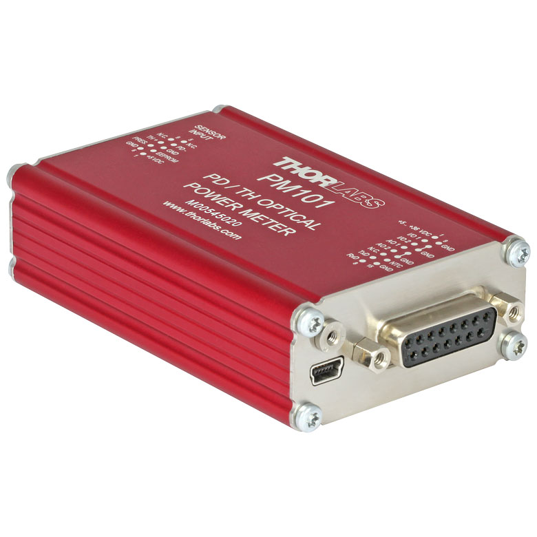
- PM101 Series Power Meter Interfaces with External Readout (Version 2.0 or Later)
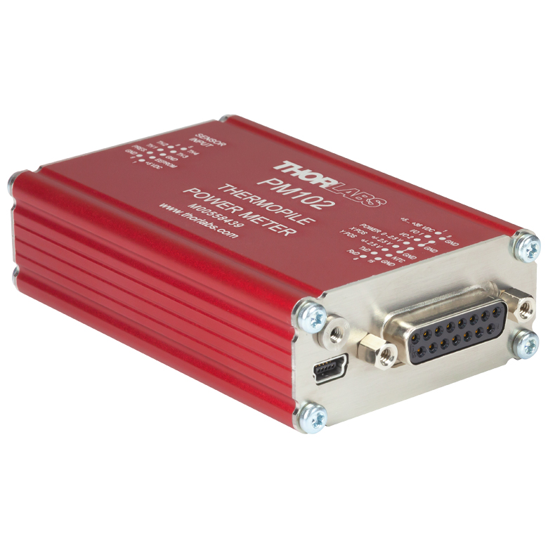
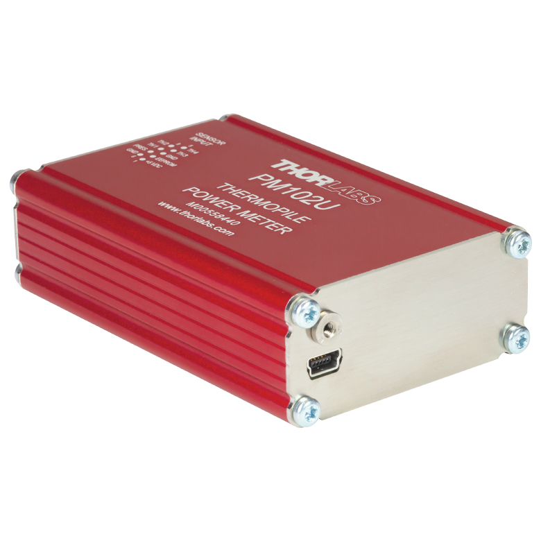
- PM102 Series Power Meter Interfaces with External Readout (Version 2.1 or Later)
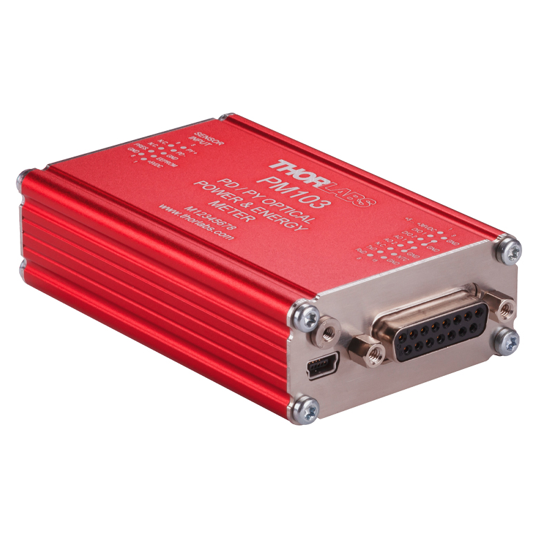
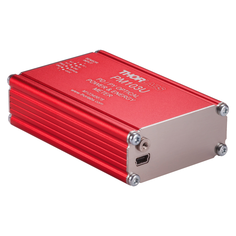
- PM103 Series Power Meter Interfaces with External Readout (Version 3.0 or Later)
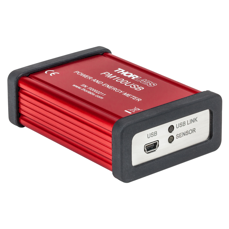
- PM100USB USB Interface Digital Power and Energy Meter
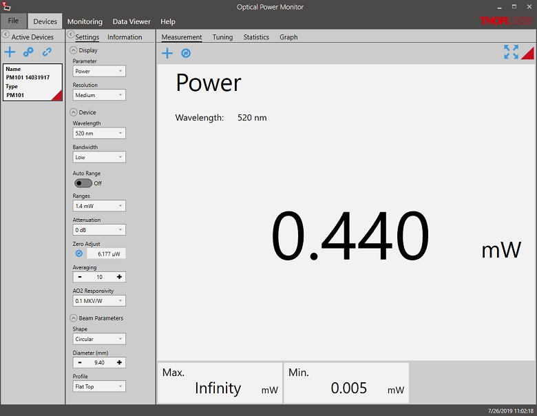
Optical Power Monitor
The Optical Power Monitor GUI software features power measurement, readout from up to eight power meters, and remote wireless operation.
For details on specific software features, please see the user manual.
Users interested in the legacy Power Meter Software can find it by visiting the software page.
The PM101 Series Power Meters are only compatible with version 2.0 or later. The PM102 Series Power Meters are only compatible with version 2.1 or later. The PM103 Series Power and Energy Meters are only compatible with version 3.0 or later. The PM5020 Console is only compatible with version 4.0 or later.
Optical Power Monitor GUI Software for Touchscreen, Handheld, and USB-Interface Power Meters
Features
- Operate up to Eight Power Meters Simultaneously
- Record and Analyze Measurements in Real Time
- Intuitive Analog Display and Graphing Modes
- Configurable Long-Term Data Logging
- Also Supports Position Measurements with Thermal Position & Power Sensors
- Compatible with USB and Bluetooth® Connections
The Optical Power Monitor software GUI enables seamless control of up to eight power meters that are connected via USB, RS232, or Bluetooth® wireless technologya. The latest software, firmware, drivers, and utilities for these power meters can be downloaded here.
Multiple data measurement and analysis functions are integrated into the GUI package. The interface offers a user-friendly design with minimal use of color and low brightness that is ideal use in dark lab environments while wearing laser safety glasses. Measured data can be displayed in real time as a simulated analog needle, digital values, line graph, or bar graph. Continuously logged and short-term measurements can be recorded for data viewing and analysis at a later point. A built-in statistics mode analyzes measured data and continuously updates to reflect new measurements within the pre-determined measurement period. Beam position measurements are also supported when used with our thermal position & power sensors.
The Optical Power Monitor software package installs the GUI, which then can be used to control the touchscreen, handheld, or USB-interface power meters. Firmware updates for supported power meters are also available. Programming examples and drivers for interfacing with our power and energy meter consoles using LabVIEW, C/C++, Visual C#, and Python are installed with the software; refer to the manual for details.
Please note that the Optical Power Monitor Software uses different drivers than the Power Meter Utilities Software and Thorlabs recommends using the new driver TLPM.dll. For users who wish to use the legacy Power Meter Software or use custom software designed using the older PM100D.dll driver, a Power Meter Driver Switcher program is included for easy swapping of the installed driver between the two versions.
a. The PM160, PM160T, and PM160T-HP power meters are equipped with Bluetooth® connections.
Click to Enlarge
Power Measurement Mode: Set up and configure up to eight power meters.
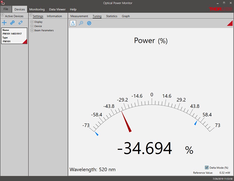
Click to Enlarge
Power Tuning Mode: Simulated analog needle and digital measurement value provided. Delta Mode, enabled above, shows the fluctuation range during the measurement period.
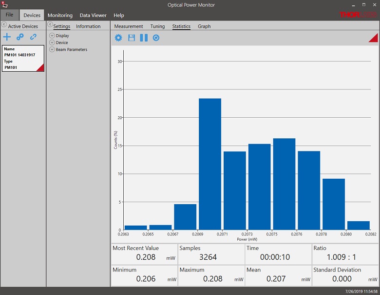
Click to Enlarge
Power Statistics Mode: Calculate numerical statistics for a pre-determined measurement period. The panel displays the analyzed values in a bar graph and the results as numerical values.
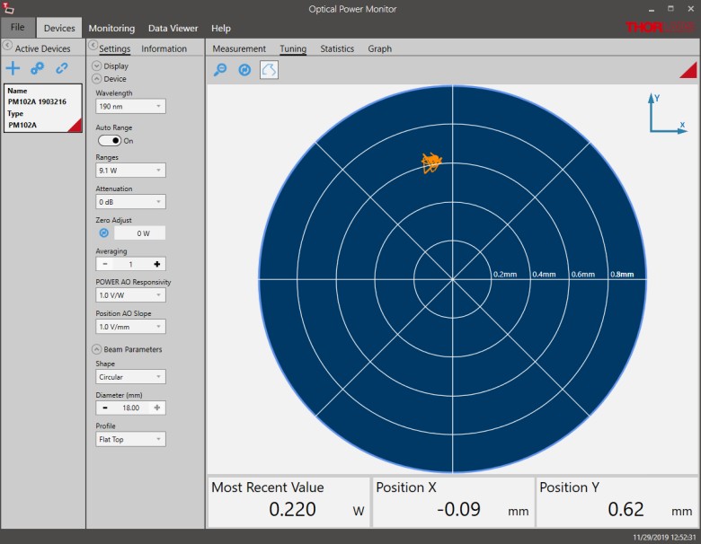
Click to Enlarge
Position Tuning Mode: Tuning mode can be used with a thermal position & power sensor to aid in beam alignment.
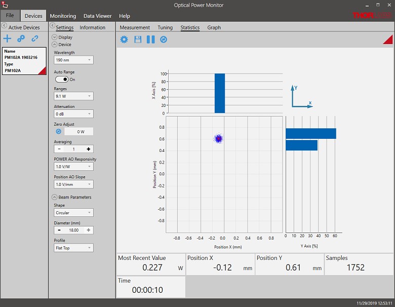
Click to Enlarge
Position Statistics Mode: Statistics mode also provides aggregate information for thermal position & power sensors.
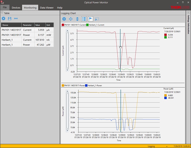
Click to Enlarge
Data Logging: Enable long-term measurement and simultaneous recording from up to eight power meters. Save data as .csv files for later processing while measurement results are displayed in a graph in real time.
Pulsed Laser Emission: Power and Energy Calculations

Determining whether emission from a pulsed laser is compatible with a device or application can require referencing parameters that are not supplied by the laser's manufacturer. When this is the case, the necessary parameters can typically be calculated from the available information. Calculating peak pulse power, average power, pulse energy, and related parameters can be necessary to achieve desired outcomes including:
- Protecting biological samples from harm.
- Measuring the pulsed laser emission without damaging photodetectors and other sensors.
- Exciting fluorescence and non-linear effects in materials.
Pulsed laser radiation parameters are illustrated in Figure 1 and described in the table. For quick reference, a list of equations are provided below. The document available for download provides this information, as well as an introduction to pulsed laser emission, an overview of relationships among the different parameters, and guidance for applying the calculations.
|
Equations: |
||||
 |
and |  |
||
 |
||||
 |
||||
 |
||||
Peak power and average power calculated from each other: |
||||
 |
and |  |
||
| Peak power calculated from average power and duty cycle*: | ||||
 |
*Duty cycle ( ) is the fraction of time during which there is laser pulse emission. ) is the fraction of time during which there is laser pulse emission. |
|||
Click to Enlarge
Figure 1: Parameters used to describe pulsed laser emission are indicated in the plot (above) and described in the table (below). Pulse energy (E) is the shaded area under the pulse curve. Pulse energy is, equivalently, the area of the diagonally hashed region.
| Parameter | Symbol | Units | Description | ||
|---|---|---|---|---|---|
| Pulse Energy | E | Joules [J] | A measure of one pulse's total emission, which is the only light emitted by the laser over the entire period. The pulse energy equals the shaded area, which is equivalent to the area covered by diagonal hash marks. | ||
| Period | Δt | Seconds [s] | The amount of time between the start of one pulse and the start of the next. | ||
| Average Power | Pavg | Watts [W] | The height on the optical power axis, if the energy emitted by the pulse were uniformly spread over the entire period. | ||
| Instantaneous Power | P | Watts [W] | The optical power at a single, specific point in time. | ||
| Peak Power | Ppeak | Watts [W] | The maximum instantaneous optical power output by the laser. | ||
| Pulse Width |  |
Seconds [s] | A measure of the time between the beginning and end of the pulse, typically based on the full width half maximum (FWHM) of the pulse shape. Also called pulse duration. | ||
| Repetition Rate | frep | Hertz [Hz] | The frequency with which pulses are emitted. Equal to the reciprocal of the period. | ||
Example Calculation:
Is it safe to use a detector with a specified maximum peak optical input power of 75 mW to measure the following pulsed laser emission?
- Average Power: 1 mW
- Repetition Rate: 85 MHz
- Pulse Width: 10 fs
The energy per pulse:

seems low, but the peak pulse power is:

It is not safe to use the detector to measure this pulsed laser emission, since the peak power of the pulses is >5 orders of magnitude higher than the detector's maximum peak optical input power.
Thorlabs offers a wide selection of power and energy meter consoles and interfaces for operating our power and energy sensors. Key specifications of all of our power meter consoles and interfaces are presented below to help you decide which device is best for your application. We also offer self-contained wireless power meters and compact USB power meters.
When used with our C-series sensors, Thorlabs' power meter consoles and interfaces recognize the type of connected sensor and measure the current or voltage as appropriate. Our C-series sensors have responsivity calibration data stored in their connectors. The console will read out the responsivity value for the user-entered wavelength and calculate a power or energy reading.
- Photodiode sensors deliver a current that depends on the input optical power and the wavelength. The current is fed into a transimpedance amplifier, which outputs a voltage proportional to the input current. The photodiode's responsivity is wavelength dependent, so the correct wavelength must be entered into the console for an accurate power reading. The console reads out the responsivity for this wavelength from the connected sensor and calculates the optical power from the measured photocurrent.
- Thermal sensors deliver a voltage proportional to the input optical power. Based on the measured sensor output voltage and the sensor's responsivity, the console will calculate the incident optical power.
- Energy sensors are based on the pyroelectric effect. They deliver a voltage peak proportional to the pulse energy. If an energy sensor is recognized, the console will use a peak voltage detector and the pulse energy will be calculated from the sensor's responsivity.
The consoles and interfaces are also capable of providing a readout of the current or voltage delivered by the sensor. Select models also feature an analog output.
Consoles
| Item # | PM100A | PM100D | PM400 | PM5020 |
|---|---|---|---|---|
| (Click Photo to Enlarge) | 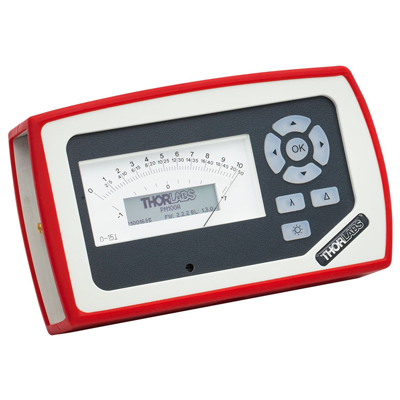 |
 |
 |
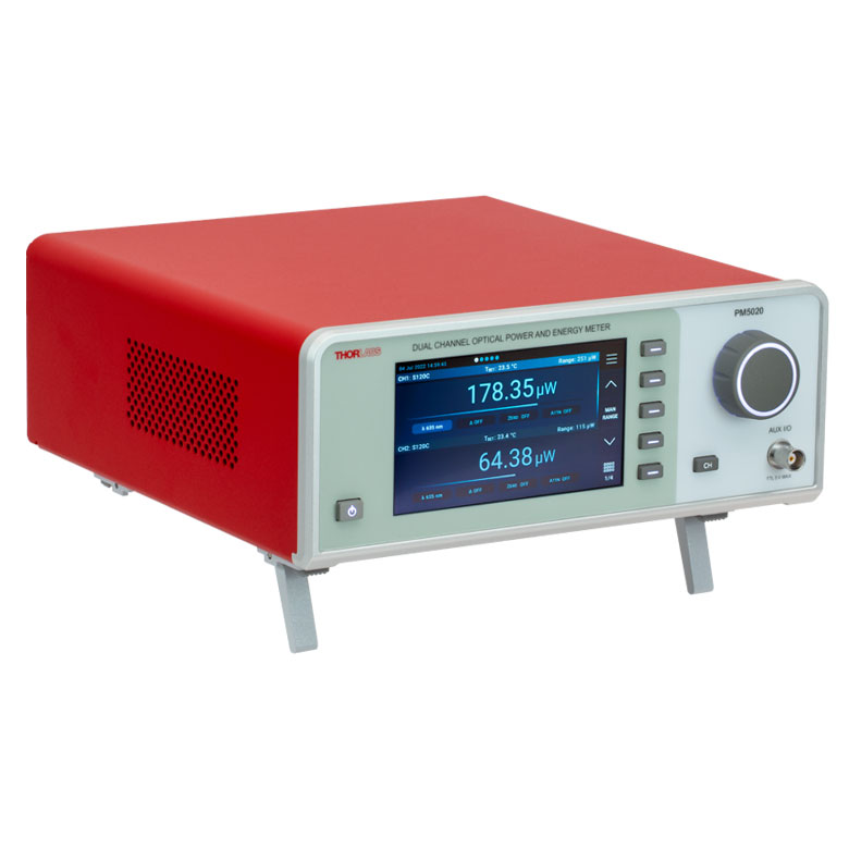 |
| Key Features | Analog Power Measurements | Digital Power and Energy Measurements | Digital Power and Energy Measurements, Touchscreen Control | Dual Channel |
| Compatible Sensors | Photodiode and Thermal Power | Photodiode Power, Thermal Power, and Pyroelectric Energya | Photodiode Power, Thermal Power, Thermal Power and Position, and Pyroelectric Energya | Photodiode Power, Thermal Power, Thermal Power and Position, and Pyroelectric Energy |
| Housing Dimensions (H x W x D) |
7.24" x 4.29" x 1.61" (184 mm x 109 mm x 41 mm) |
7.09" x 4.13" x 1.50" (180 mm x 105 mm x 38 mm) |
5.35" x 3.78" x 1.16" (136.0 mm x 96.0 mm x 29.5 mm) |
9.97" x 4.35" x 11.56" (253.2 mm x 110.6 mm x 293.6 mm) |
| Channels | 1 | 2 | ||
| External Temperature Sensor Input (Sensor not Included) | - | - | Readout and Record Temperature Over Time | Readout and Record Temperature Over Time |
| External Humidity Sensor Input (Sensor not Included) | - | - | Readout and Record Humidity Over Time | Readout and Record Humidity Over Time |
| Input/Output Ports | - | 4 GPIO, Programmable | 4 Configurable Digital I/O Channels | |
| Shutter Control | - | - | - | Support for SH05R(/M) or SH1(/M) Optical Shutter with Interlock Input |
| Fan Control | - | - | - | |
| Source Spectral Correction | - | - | ||
| Attenuation Correction | - | - | ||
| External Trigger Input | - | - | - | |
| Display | ||||
| Type | Mechanical Needle and LCD Display with Digital Readout | 320 x 240 Pixel Backlit Graphical LCD Display | Protected Capacitive Touchscreen with Color Display | |
| Dimensions | Digital: 1.9" x 0.5" (48.2 mm x 13.2 mm) Analog: 3.54" x 1.65" (90.0 mm x 42.0 mm) |
3.17" x 2.36" (81.4 mm x 61.0 mm) |
3.7" x 2.1" (95 mm x 54 mm) |
4.32" x 2.43" (109.7 mm x 61.6 mm) |
| Refresh Rate | 20 Hz | 10 Hz (Numerical) 25 Hz (Analog Simulation) |
25 Hz | |
| Measurement Viewsb | ||||
| Numerical | ||||
| Mechanical Analog Needle | - | - | - | |
| Simulated Analog Needle | - | |||
| Bar Graph | - | |||
| Trend Graph | - | |||
| Histogram | - | - | - | |
| Statistics | ||||
| Memory | ||||
| Type | - | SD Card | NAND Flash | SD Card |
| Size | - | 2 GB | 4 GB | 8 GB |
| Power | ||||
| Battery | LiPo 3.7 V 1300 mAh | LiPo 3.7 V 2600 mAh | - | |
| External | 5 VDC via USB or Included AC Adapter | 5 VDC via USB | Line Voltage: 100 - 240 V | |


| Posted Comments: | |
Bryn Parry
(posted 2024-02-23 17:21:34.487) Please provide a metric option for this (or just default to metric parts if shipping to europe), I ordered it without realising that the post, post holder and base supplied with it are imperial ones! hchow
(posted 2024-02-26 06:52:34.0) Dear Mr. Parry, thank you for your feedback. My apologies. I am sorry to hear that you received the wrong items. I will personally reach out to you to rectify this mistake. Shengli Pu
(posted 2023-03-12 06:01:58.203) 我们曾经购买的“PM203”出现故障,还可以维修吗? jgreschler
(posted 2023-03-15 03:28:18.0) Thank you for reaching out to Thorlabs. The PM203 was obsoleted in 2019 and as such our ongoing repair service is limited but not terminated. I've reached out to you directly to discuss whether the repair you have falls into our capability. 80kmh
(posted 2017-09-11 18:35:39.067) Dear sir/madam,
I want to use this powermeter module.
Regarding the software, is it providing the software developing file for example SDK or library and etc...
I need it to develop my software using this item. swick
(posted 2017-09-12 03:56:58.0) This is a response from Sebastian at Thorlabs. Thank you for the inquiry. Our Power Meter Consoles can be controlled with SCPI commands. After installing the software package you can find examples e.g. in C# at path:
C:\Program Files (x86)\IVI Foundation\VISA\WinNT\PM100D\Example
I will contact you directly to provide further information about the driver. anatole.heliot
(posted 2016-04-26 04:45:15.563) Hello,
I'm using the PM120D pack (with S120C photodiode) for measuring an light intensity in function of time. I'm wondering if I can have a response time on the order of microsecond with the analog output.
Thank you,
Anatole HELIOT shallwig
(posted 2016-04-27 10:41:24.0) This is a response from Stefan at Thorlabs. Thank you very much for your inquiry. The analog output Bandwidth is DC-100 kHz dependent on the sensor. For the photodiodes sensors you can find the output bandwidth dependent on the current range in the manual on page 68 https://www.thorlabs.com/thorcat/17600/PM100D-Manual.pdf . I will contact you directly to check your application in more detail. jvigroux
(posted 2012-05-16 07:51:00.0) A resposne from Julien at Thorlabs: Dear Ken, thank you for your feedback! We indeed do not write explicitly that a post holder and a base are included in those bundles. We will modify the text on the webpage to make the exact component list clearer. ken
(posted 2012-05-16 08:23:07.0) They come with a post/holder/base? We do not see the information in the page here though. Ken jvigroux
(posted 2011-11-17 13:52:00.0) A response from Julien at Thorlabs: Dear Martin, I am really sorry about this inconvenience. We will ship you a replacement immediately. Concerning your question about the quality control, we do check each power meter individually before shipment. I unfortunately do not know what the exact problem with your console is but I assume something must have happened during the shipment. We will inspect the unit as soon as we have it back and take the appropriate measures to prevent such issue from happening again. I will contact you directly to sort out the shipping details for the replacement. m.j.slaman
(posted 2011-11-17 12:24:11.0) I have unpacked my PM204 (consists of a PM200 and a S120VC) but it is not reading anything. The measured value remains inf as well as the minimum and maximum value. Also in the applied software I don`t see any reading (value remains 0 or ---). I have auto ranging on an tried with several light conditions. In the software an indicator shows A (waiting for new measurement value)(in the left top corner) while I expect sometimes a T of "trigger". The detector itself is ok since it is functioning on a PM100D console. I have attached also a second detector (S155C)on the PM200 without success. I have checked for firmwareupdates but there are non available on the website. I can not find any reset functions or trigger-arm functions in the manual nor in the software. Did anybody check the console before chipping? That must be since a callibration sheet was shipped with it?!?!
How do I fix it?
Martin bdada
(posted 2011-10-10 17:12:00.0) Response from Buki at Thorlabs:
Thank you for using our Feedback tool. Our sensors measure light from 200nm upwards. We will contact you regarding the possibility of a custom sensor that can measure 193nm. matt.hansen
(posted 2011-10-10 13:43:09.0) To Whom:
What would bea good detector to use with our PM310D meter to measure 193 nm light in the nW range ?
Matt Hansen bdada
(posted 2011-10-06 20:36:00.0) Response from Buki at Thorlabs:
Thank you for your feedback. The PM120A has been replaced with the PM120D, which is designed for 400 - 1100nm and power levels of 50nW to 50mW. We will contact you to discuss your application. ryanlee
(posted 2011-10-06 17:58:46.0) Hi
Can you advise if the PM120A is suitable to check the below mentioned items?
1) 3M Curing Light 2500
http://dentista.pinoydental.com/component/page,shop.product_details/flypage,shop.flypage/product_id,20/category_id,9/manufacturer_id,0/option,com_virtuemart/Itemid,70/vmcchk,1/
2) Dymax Bluewave 75
http://www.dymax.com/products/curing_equipment/uv_spot_lamps/bluewave_75.php
Thanks!
Regards
Ryan jjurado
(posted 2011-05-04 13:27:00.0) Response from Javier at Thorlabs to dBolles: Thank you very much for contacting us. Yes, all of our C series sensors have NIST-traceable calibration data, as well as sensor information, saved in the DB9 connector. This information is automatically retrieved by our power meters as soon as the sensor is connected. dBolles
(posted 2011-05-04 08:41:42.0) Do all of your C detectors have the calibration data for the detector stored in the DB connector? fcao
(posted 2011-01-26 17:59:05.0) Hi Simon. Our China office will contact you shortly. simonhedwin
(posted 2011-01-26 15:05:21.0) ??PM121D?????? |
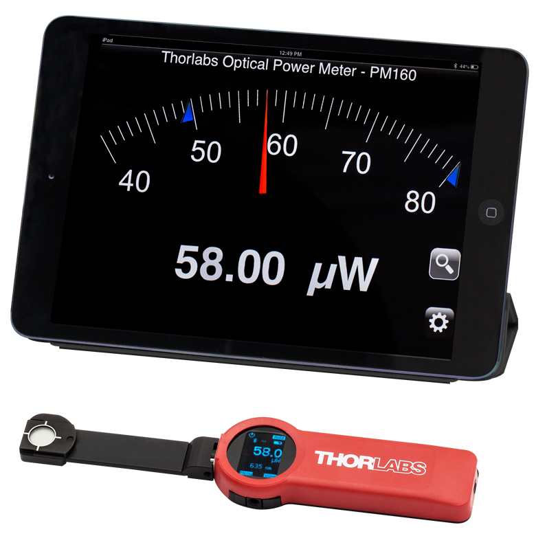
Click to Enlarge
The PM160 wireless power meter, shown here with an iPad mini (not included), can be remotely operated using Apple mobile devices.
This tab outlines the full selection of Thorlabs' power and energy sensors. Refer to the lower right table for power meter console and interface compatibility information.
In addition to the power and energy sensors listed below, Thorlabs also offers all-in-one, wireless, handheld power meters and compact USB power meter interfaces that contain either a photodiode or a thermal sensor, as well as power meter bundles that include a console, sensor head, and post mounting accessories.
Thorlabs offers four types of sensors:
- Photodiode Sensors: These sensors are designed for power measurements of monochromatic or near-monochromatic sources, as they have a wavelength dependent responsivity. These sensors deliver a current that depends on the input optical power and the wavelength. The current is fed into a transimpedance amplifier, which outputs a voltage proportional to the input current.
- Thermal Sensors: Constructed from material with a relatively flat response function across a wide range of wavelengths, these thermopile sensors are suitable for power measurements of broadband sources such as LEDs and SLDs. Thermal sensors deliver a voltage proportional to the input optical power.
- Thermal Position & Power Sensors: These sensors incorporate four thermopiles arranged as quadrants of a square. By comparing the voltage output from each quadrant, the unit calculates the beam's position.
- Pyroelectric Energy Sensors: Our pyroelectric sensors produce an output voltage through the pyroelectric effect and are suitable for measuring pulsed sources, with a repetition rate limited by the time constant of the detector. These sensors will output a peak voltage proportional to the incident pulse energy.
| Console Compatibility | ||||||||
|---|---|---|---|---|---|---|---|---|
| Console Item # | PM100A | PM100D | PM400 | PM5020 | PM101 Series |
PM102 Series |
PM103 Series |
PM100USB |
| Photodiode Power |  |
|
|
|
|
- | |
|
| Thermal Power | |
|
|
|
|
|
- | |
| Thermal Position | - | - | |
|
- | |
- | - |
| Pyroelectric Energy | - | a |
a |
|
- | - | |
a |
Power and Energy Sensor Selection Guide
There are two options for comparing the specifications of our Power and Energy Sensors. The expandable table below sorts our sensors by type (e.g., photodiode, thermal, or pyroelectric) and provides key specifications.
Alternatively, the selection guide graphic further below arranges our entire selection of photodiode and thermal power sensors by wavelength (left) or optical power range (right). Each box contains the item # and specified range of the sensor. These graphs allow for easy identification of the sensor heads available for a specific wavelength or power range.
| Photodiode Power Sensors |
|---|


| Thermal Power Sensors |
|---|


| Thermal Position & Power Sensors |
|---|

| Pyroelectric Energy Sensors |
|---|


Sensor Options
(Arranged by Wavelength Range)
Sensor Options
(Arranged by Power Range)
| Kit Item # | PM120VA |
|---|---|
| Click Image to Enlarge | 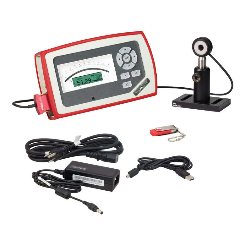 |
| Included Console Item # |
PM100A |
| Display | Analog Needle with 132 x 32 Pixel LCD |
| Connectivity | USB 2.0 Connectivity |
| Console Sensor Compatibility | All C-Series Photodiode and Thermal Power Sensors |
| Included Sensor | S120VC |
|---|---|
| Wavelength Range | 200 - 1100 nm |
| Power Range | 50 nW - 50 mW |
| Resolution | 1 nW |
| Detector Type | Si Photodiode |
| Aperture | Ø9.5 mm |
| Spec Sheet |
This kit includes our PM100A console, an S120VC photodiode power sensor, and a post assembly, consisting of a BA2 base, PH2 post holder, and TR2 Ø1/2" post. This is a general-purpose kit for low-power lasers (50 nW - 50 mW) within the visible and NIR regions. Surrounding the sensor's active area is a fluorescing alignment disk, which absorbs light from 200 - 525 nm. Many of our laser diodes and HeNe lasers are suitable for use with this power meter kit.
Thorlabs offers a recalibration service for this power and energy meter kit, which can be ordered using Item # CAL-UVPD below. Enter only the Part # and Serial # of the sensor that requires recalibration and include the corresponding console for recalibration during shipment.
We recommend recalibrating your sensor and console as a pair; however, if you would like to recalibrate only your console, use Item # CAL-PM1 below.
| Kit Item # | PM120D | PM400K1 |
|---|---|---|
| Click Image to Enlarge | 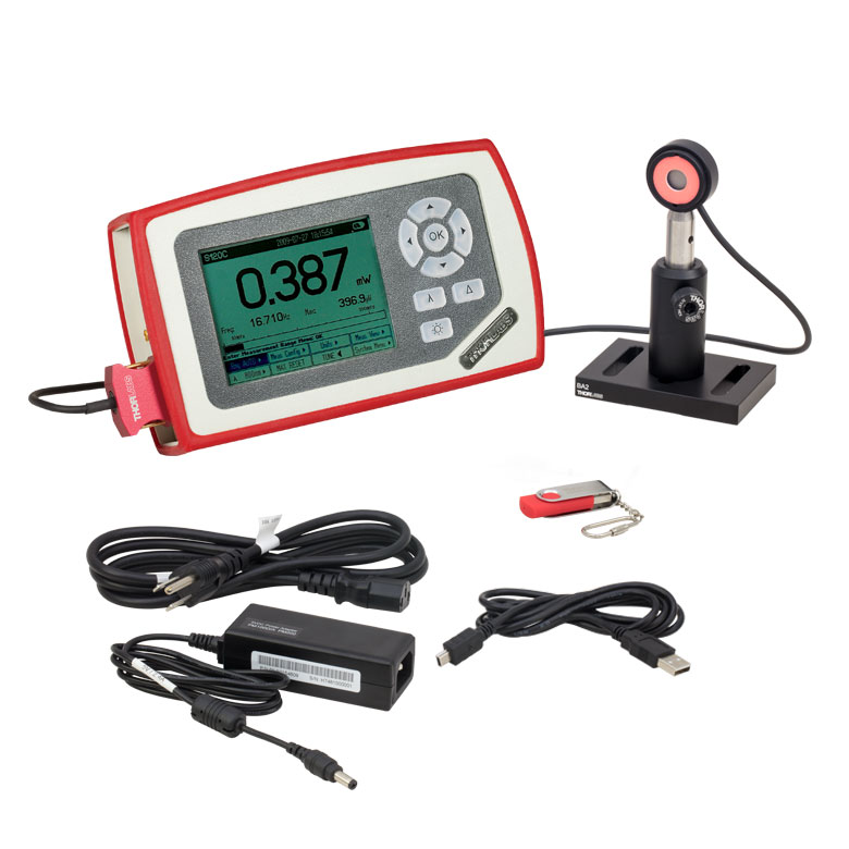 |
 |
| Included Console Item # | PM100D | PM400 |
| Display | 4" Backlit Digital Display, 320 x 240 Pixel Resolution |
4.3" Capacitive Color Touchscreen, WQVGA Resolution |
| Connectivity | USB 2.0 Connectivity | |
| Console Sensor Compatibility |
All C-Series Photodiode and Thermal Power Sensors as Well as All Pyroelectric Energy Sensors |
|
| Included Sensor | S120C |
|---|---|
| Wavelength Range | 400 - 1100 nm |
| Power Range | 50 nW - 50 mW |
| Resolution | 1 nW |
| Detector Type | Si Photodiode |
| Aperture | Ø9.5 mm |
| Spec Sheet |
Each kit includes our PM100D or PM400 power meter console, a S120C photodiode sensor, and a post assembly, consisting of a BA2 base, PH2 post holder, and TR2 Ø1/2" post. This is a general purpose kit for low power lasers (50 nW - 50 mW) within the visible and NIR. Surrounding the sensor's active area is a fluorescing alignment disk, which absorbs light from 400 - 640 nm and 800 - 1700 nm. Many of our laser diodes and HeNe lasers are suitable for use with this power meter kit.
Thorlabs offers a recalibration service for these power and energy meter kits, which can be ordered using Item # CAL-PD below. Enter only the Part # and Serial # of the sensor that requires recalibration and include the corresponding console for recalibration during shipment.
We recommend recalibrating your sensor and console as a pair; however, if you would like to recalibrate only your console, use Item # CAL-PM1 below.
| Kit Item # | PM121D | PM400K2 |
|---|---|---|
| Click Image to Enlarge | 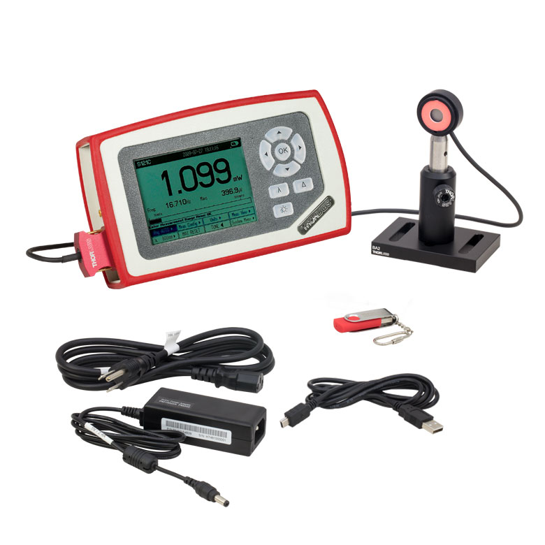 |
 |
| Included Console Item # | PM100D | PM400 |
| Display | 4" Backlit Digital Display, 320 x 240 Pixel Resolution |
4.3" Capacitive Color Touchscreen, WQVGA Resolution |
| Connectivity | USB 2.0 Connectivity | |
| Console Sensor Compatibility |
All C-Series Photodiode and Thermal Power Sensors as Well as All Pyroelectric Energy Sensors |
|
| Included Sensor | S121C |
|---|---|
| Wavelength Range | 400 - 1100 nm |
| Power Range | 500 nW - 500 mW |
| Resolution | 10 nW |
| Detector Type | Si Photodiode |
| Aperture | Ø9.5 mm |
| Spec Sheet |
Each kit includes our PM100D or PM400 console, a S121C photodiode sensor, and a post assembly, consisting of a BA2 base, PH2 post holder, and TR2 Ø1/2" post. This is a general purpose kit for low to medium power lasers (500 nW - 500 mW) within the visible and NIR spectrums (<1100 nm). It is similar to the S120C, which is included in the kit above, but an ND filter attenuates the light before the sensor. Surrounding the sensor's active area is a fluorescing alignment disk, which absorbs light from 400 - 640 nm and 800 - 1700 nm.
Thorlabs offers a recalibration service for these power and energy meter kits, which can be ordered using Item # CAL-PD below. Enter only the Part # and Serial # of the sensor that requires recalibration and include the corresponding console for recalibration during shipment.
We recommend recalibrating your sensor and console as a pair; however, if you would like to recalibrate only your console, use Item # CAL-PM1 below.
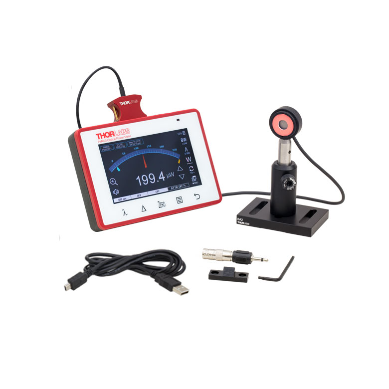
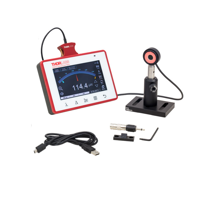
| Kit Item # | PM130D | PM400K3 |
|---|---|---|
| Click Image to Enlarge | 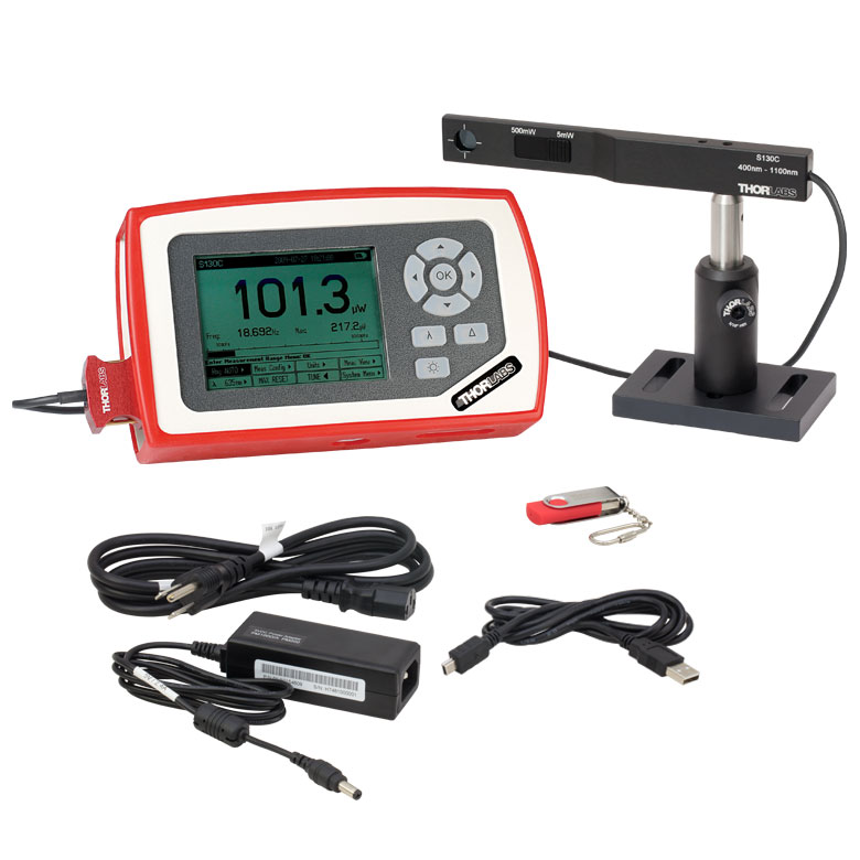 |
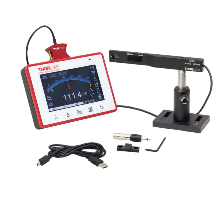 |
| Included Console Item # | PM100D | PM400 |
| Display | 4" Backlit Digital Display, 320 x 240 Pixel Resolution |
4.3" Capacitive Color Touchscreen, WQVGA Resolution |
| Connectivity | USB 2.0 Connectivity | |
| Console Sensor Compatibility |
All C-Series Photodiode and Thermal Power Sensors as Well as All Pyroelectric Energy Sensors |
|
| Included Sensor | S130C |
|---|---|
| Wavelength Range | 400 - 1100 nm |
| Power Range | 500 pW - 5 mW (Up to 500 mW with Filter)a |
| Resolution | 100 pW |
| Detector Type | Si Photodiode |
| Aperture | Ø9.5 mm |
| Spec Sheet |
Each kit includes our PM100D or PM400 console, a S130C photodiode power sensor, and a post assembly, consisting of a BA2 base, PH2 post holder, and TR2 Ø1/2" post. The kit's slim sensor head is ideal for use in tight spaces as it is only 0.2"
(5 mm) thick at its sensor. A sliding neutral density filter extends the power range that the sensor can be used to measure. With the filter out of the beam path, the power detection range is
500 pW to 5 mW. With the filter in the beam path, power detection from 50 nW to 500 mW is possible; however, power levels below 5 mW should be detected without the filter in the beam path for optimal results. The filter's position is automatically detected and accounted for by the power meter console.
Thorlabs offers a recalibration service for these power and energy meter kits, which can be ordered using Item # CAL-PD2 below. Enter only the Part # and Serial # of the sensor that requires recalibration and include the corresponding console for recalibration during shipment.
We recommend recalibrating your sensor and console as a pair; however, if you would like to recalibrate only your console, use Item # CAL-PM1 below.
| Kit Item # | PM122D | PM400K4 |
|---|---|---|
| Click Image to Enlarge | 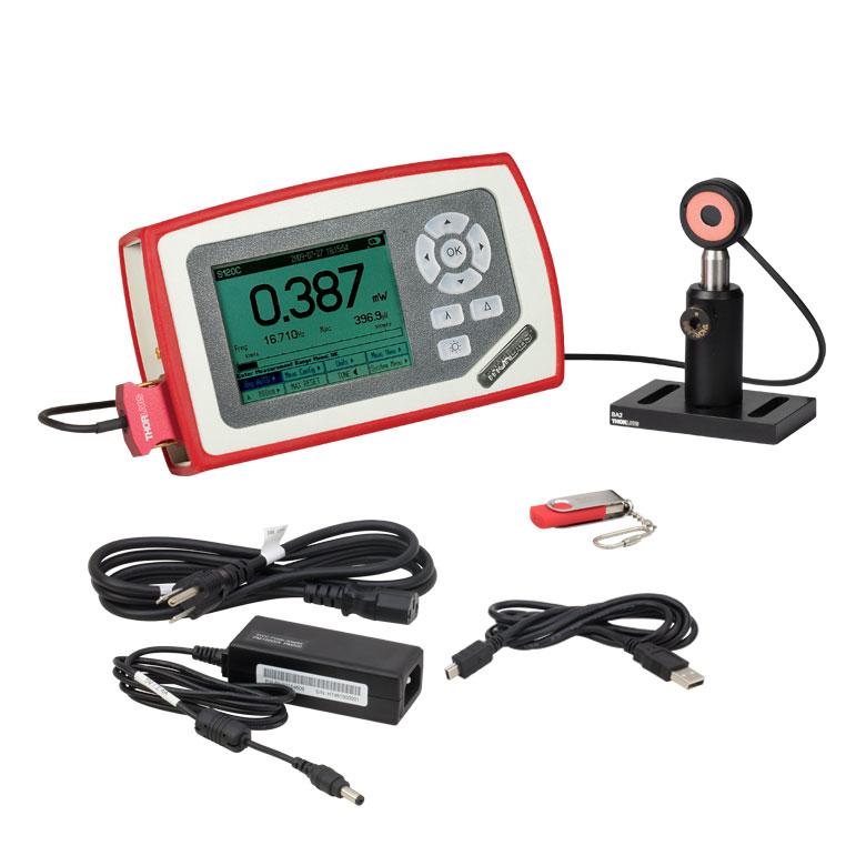 |
 |
| Included Console Item # | PM100D | PM400 |
| Display | 4" Backlit Digital Display, 320 x 240 Pixel Resolution |
4.3" Capacitive Color Touchscreen, WQVGA Resolution |
| Connectivity | USB 2.0 Connectivity | |
| Console Sensor Compatibility |
All C-Series Photodiode and Thermal Power Sensors as Well as All Pyroelectric Energy Sensors |
|
| Included Sensor | S122C |
|---|---|
| Wavelength Range | 700 - 1800 nm |
| Power Range | 50 nW - 40 mW |
| Resolution | 2 nW |
| Detector Type | Ge Photodiode |
| Aperture | Ø9.5 mm |
| Spec Sheet |
Each kit includes our PM100D or PM400 console, a S122C photodiode sensor, and a post assembly, consisting of a BA2 base, PH2 post holder, and TR2 Ø1/2" post. This combination is ideal for customers working with wavelengths in the far red to NIR (700 - 1800 nm). Surrounding the sensor's active area is a fluorescing alignment disk, which absorbs light from 400 - 640 nm and 800 - 1700 nm.
Thorlabs offers a recalibration service for these power and energy meter kits, which can be ordered using Item # CAL-IRPD below. Enter only the Part # and Serial # of the sensor that requires recalibration and include the corresponding console for recalibration during shipment.
We recommend recalibrating your sensor and console as a pair; however, if you would like to recalibrate only your console, use Item # CAL-PM1 below.
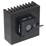
| Kit Item # | PM125D | PM400K5 |
|---|---|---|
| Click Image to Enlarge |  |
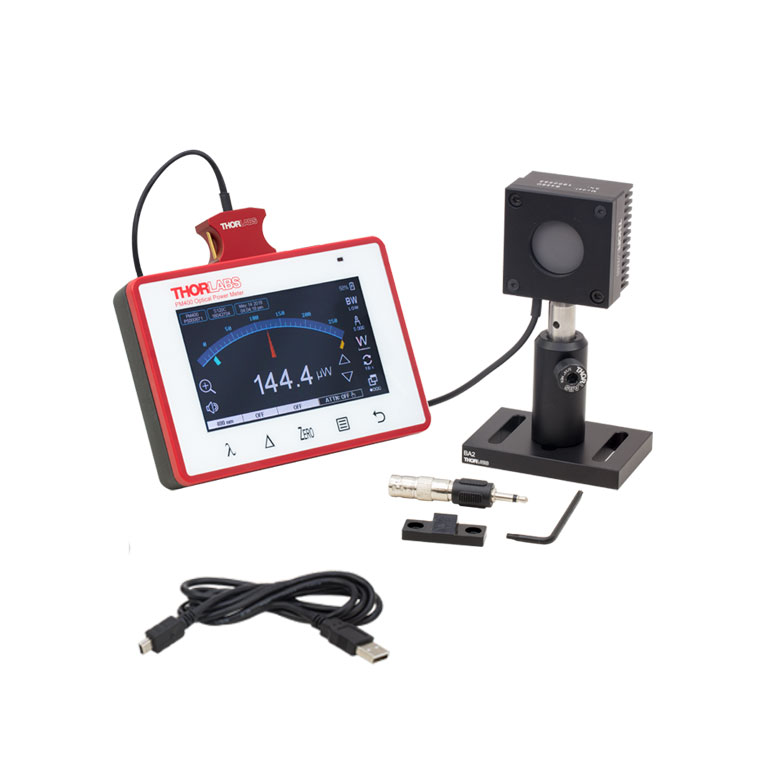 |
| Included Console Item # | PM100D | PM400 |
| Display | 4" Backlit Digital Display, 320 x 240 Pixel Resolution |
4.3" Capacitive Color Touchscreen, WQVGA Resolution |
| Connectivity | USB 2.0 Connectivity | |
| Console Sensor Compatibility |
All C-Series Photodiode and Thermal Power Sensors as Well as All Pyroelectric Energy Sensors |
|
| Included Sensor | S425C |
|---|---|
| Wavelength Range | 0.19 - 20 µm |
| Power Range | 2 mW - 10 W |
| Resolution | 100 µW |
| Detector Type | Thermal |
| Aperture | Ø25.4 mm |
| Spec Sheet |
Each kit includes our PM100D or PM400 power meter console, an S425C photodiode sensor, and a post assembly, consisting of a BA2 base, PH2 post holder, and TR2 Ø1/2" post. This is a general-purpose kit for customers working with higher powered lasers (up to 10 W) or longer wavelengths (up to 20 µm). The S425C thermal sensor has an exceptionally fast response time of 0.6 s.
Thorlabs offers a recalibration service for these power and energy meter kits, which can be ordered using Item # CAL-THPY below. Enter only the Part # and Serial # of the sensor that requires recalibration and include the corresponding console for recalibration during shipment.
We recommend recalibrating your sensor and console as a pair; however, if you would like to recalibrate only your console, use Item # CAL-PM1 below.
| Calibration Service Item # | Compatible Sensors |
|---|---|
| CAL-UVPD | S120VC |
| CAL-PD | S116C, S120C, S121C, S170C, S171C, S140C, S142C, S142CL, S150C, S151C, PM16-120, PM16 |
| CAL-UVPD2 | S130VC |
| CAL-PD2 | S130C, PM16-130, PM160 |
| CAL-IRPD | S122C, S144C, S145C, S145CL, S146C, S154C, S155C, PM16-122, PM16-144 |
| CAL-IRPD2 | S132C |
| CAL-MIRPD | S148C, S180C |
Thorlabs offers recalibration services for our photodiode optical power sensors. To ensure accurate measurements, we recommend recalibrating the sensors annually. Recalibration of a single-channel power and/or energy meter console or interface is included with the recalibration of a sensor at no additional cost. If you wish to calibrate one or more sensors with a dual-channel console, each sensor and console calibration service will need to be purchased individually. For more details on these recalibration services, please click the Documents (![]() ) icons below.
) icons below.
Refer to the table to the right for the appropriate calibration service Item # that corresponds to your power sensor.
Requesting a Calibration
Thorlabs provides two options for requesting a calibration:
- Complete the Returns Material Authorization (RMA) form. When completing the RMA form, please enter your name, contact information, the Part #, and the Serial # of each item being returned for calibration; in the Reason for Return field, select "I would like an item to be calibrated." All other fields are optional. Once the form has been submitted, a member of our RMA team will reach out to provide an RMA Number, return instructions, and to verify billing and payment information.
- Select the appropriate sensor calibration Item # below, enter the Part # and Serial # of the sensor that requires recalibration, and then Add to Cart. If you would like a console calibrated with your sensor, repeat this process for Item # CAL-PM1 or CAL-PM2 below, entering the console Item # and Serial #. A member of our RMA team will reach out to coordinate the return of the item(s) for calibration. Note that each console calibration Item # represents the cost of calibrating a console alone; if requesting a single-channel console calibration with a sensor calibration, the appropriate discount will be applied when your request is processed. Should you have other items in your cart, note that the calibration request will be split off from your order for RMA processing.
Please Note: To ensure your item being returned for calibration is routed appropriately once it arrives at our facility, please do not ship it prior to being provided an RMA Number and return instructions by a member of our team.
| Sensor Type | Sensor Item #s |
|---|---|
| Thermal Power | S175C, S302Ca, S305Ca, S310Ca, S314Ca,S322C, S350C, S370C, S401C, S405C, S415C, S425C, S425C-L, S470C, PM160T, PM160T-HP, PM16-401, PM16-405 |
| Pyroelectric Energy | ES111C, ES120C, ES145C, ES220C, ES245C, ES308C, ES312C, ES408C, ES412C |
Thorlabs offers recalibration services for our Thermal Power and Pyroelectric Energy Sensors. To ensure accurate measurements, we recommend recalibrating the sensors annually. Recalibration of a single-channel power and/or energy meter console or interface is included with the recalibration of a sensor at no additional cost. If you wish to calibrate one or more sensors with a dual-channel console, each sensor and console calibration service will need to be purchased individually.
Please note that the CAL-THPY recalibration service cannot be used for our Thermal Position & Power Sensors; recalibration for these sensors can be requested by contacting Tech Support. The table to the upper right lists the sensors for which the CAL-THPY recalibration service is available.
Requesting a Calibration
Thorlabs provides two options for requesting a calibration:
- Complete the Returns Material Authorization (RMA) form. When completing the RMA form, please enter your name, contact information, the Part #s, and the Serial #s of all sensors or consoles being returned for calibration; in the Reason for Return field, select "I would like an item to be calibrated." All other fields are optional. Once the form has been submitted, a member of our RMA team will reach out to provide an RMA Number, return instructions, and to verify billing and payment information.
- Enter the Part # and Serial # of the item that requires recalibration below and then Add to Cart. If you would like a console calibrated with your sensor, repeat this process for Item # CAL-PM1 or CAL-PM2 below, entering the console Item # and Serial #. A member of our RMA team will reach out to coordinate the return of the item(s) for calibration. Note that each console calibration Item # represents the cost of calibrating a console alone; if requesting a single-channel console calibration with a sensor calibration, the appropriate discount will be applied when your request is processed. Should you have other items in your cart, note that the calibration request will be split off from your order for RMA processing.
Please Note: To ensure your item being returned for calibration is routed appropriately once it arrives at our facility, please do not ship it prior to being provided an RMA Number and return instructions by a member of our team. Pyroelectric energy sensors returned for recalibration or servicing must include the separate BNC to DB9 adapter, which contains the sensor EEPROM.
| Calibration Service Item # | Compatible Consoles & Interfaces |
|---|---|
| Single-Channel | |
| CAL-PM1 | PM100D, PM100A, PM400, PM100USB, PM101 Series, PM102 Series, PM103 Series |
| Dual-Channel | |
| CAL-PM2 | PM5020, Previous-Generation PM320E |
These recalibration services are for the power and/or energy meter electronics of our consoles and interfaces. To ensure accurate measurements, we recommend recalibrating annually. Recalibration of a single-channel console or interface is included with these sensor recalibration services at no additional cost. If you wish to calibrate one or more sensors with a dual-channel console, each sensor and console calibration service will need to be purchased individually. For more details on these recalibration services, please click the Documents (![]() ) icons below.
) icons below.
The table to the upper right lists the power and/or energy meter consoles and interfaces that can be calibrated using the CAL-PM1 and CAL-PM2 recalibration services.
Requesting a Calibration
Thorlabs provides two options for requesting a calibration:
- Complete the Returns Material Authorization (RMA) form. When completing the RMA form, please enter your name, contact information, the Part #, and the Serial # of each item being returned for calibration; in the Reason for Return field, select "I would like an item to be calibrated." All other fields are optional. Once the form has been submitted, a member of our RMA team will reach out to provide an RMA Number, return instructions, and to verify billing and payment information.
- Select the appropriate Item # below, enter the Part # and Serial # of the item that requires recalibration, and then Add to Cart. If you would like to calibrate one or more sensors with your console, repeat this process for the appropriate sensor recalibration service above, entering the console Item # and Serial #. A member of our RMA team will reach out to coordinate return of the item(s) for calibration. Note that each console calibration Item # represents the cost of calibrating a console alone; if requesting a single-channel console calibration with a sensor calibration, the appropriate discount will be applied when your request is processed. Should you have other items in your cart, note that the calibration request will be split off from your order for RMA processing.
Please Note: To ensure your item being returned for calibration is routed appropriately once it arrives at our facility, please do not ship it prior to being provided an RMA Number and return instructions by a member of our team.