 Products Home
Photodiode Power Sensors (C-Series)
- Power Ranges Covering 100 pW to 20 W
- Wavelength Ranges Covering 200 nm to 5.5 µm
- C-Series Connector for Quick Exchange
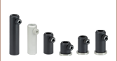
S120C
Sensor with IR
Target
S145C
Integrating Sphere Sensor
Posts and Post Holders Not Included
S140C
Integrating Sphere Sensor
S130C
Slim Sensor
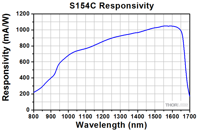
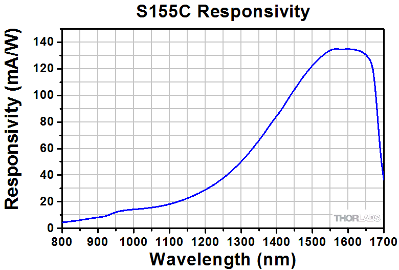
S154C
Fiber Sensor
S170C
Microscope Slide
Power Sensor Head
Integrating Sphere Sensors Shown with FC/PC Adapters (Included on Sensors with Apertures ≤Ø12 mm)
Articulating Arm Not Included
S116C
Compact Slim Sensor


Please Wait
| Power Meter Selection Guide |
|---|
| Sensors |
| Photodiode Power Sensors |
| Thermal Power Sensors |
| Thermal Position & Power Sensors |
| Pyroelectric Energy Sensors |
| Power Meter Consoles and Interfaces |
| Digital Handheld Console |
| Analog Handheld Console |
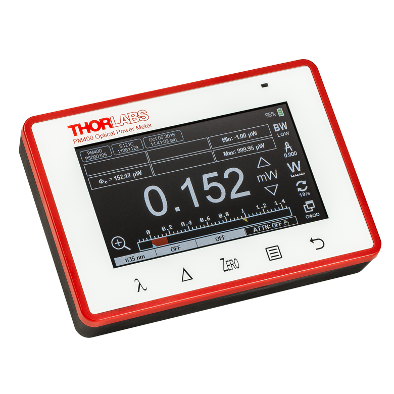
| Touchscreen Handheld Console |
| Dual-Channel Benchtop Console |
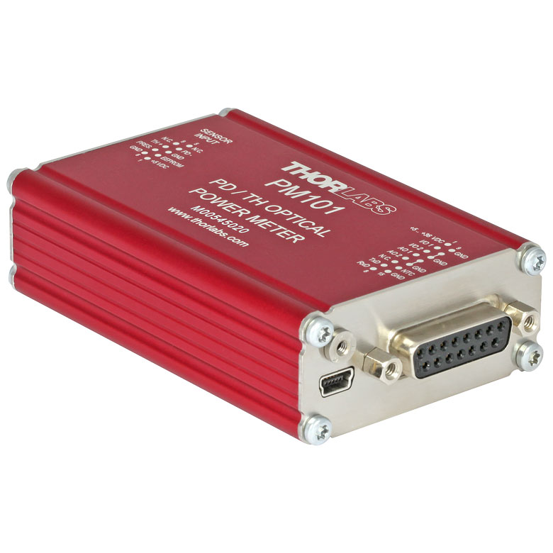
| USB Interfaces with External Readout |
| Complete Power Meters |
| Power Meter Bundles |
| Wireless Power Meters with Sensors |
| Compact USB Power Meters |
| Field Power Meters for Terminated Fibers |
Features
- Fast Response Time and High Resolution
- C-Series Connector Design for Quick Sensor Connection
- Over-Temperature Alert Sensor (Except S130 Series and S170C and NS170C Microscope Slide Sensors)
- Individually Calibrated with NIST- or PTB-Traceable Certificate of Calibration Plus Embedded Calibration Curve and Sensor Settings
Thorlabs' C-Series Photodiode Power Meter Sensors cover a wide power and wavelength range. These sensors are offered in standard, slim, microscope slide, integrating sphere, and compact fiber versions to meet your specific application requirements. They are the best sensor choice when a fast response time or high resolution is required and there is not a need for a flat spectral response.
These photodiode power meter sensors feature enhanced shielding to avoid electromagnetic interference as well as an over-temperature alert sensor to warn against damage and measurement errors due to overheating of the sensor (except the S130VC, S130C, and S132C Slim Sensors and the S170C, S171C, and NS170C Microscope Slide Sensors). For all sensors (except the S130VC, S130C, and S132C Slim Sensors and the S170C, S171C, and NS170C Microscope Slide Sensors), a set of fiber adapters is available to connect them to standard optical fiber patch cables (see below). Other fiber adapter types are available upon request.
The sensors below (except the S150C series) have universal 8-32 and M4 taps for mounting to Ø1/2" Posts. Posts and post holders are not included and sold separately.
Compatibility
The Photodiode Sensors presented here are compatible with C-Series power meter consoles including the PM400, PM100D, PM100A, and PM5020, as well as many of our C-series power and energy meter interfaces. The S150C Series Fiber Sensors are integrated into the connector itself and directly plugged into the console.
Calibration
Each sensor head is individually calibrated and is shipped with NIST- or PTB-traceable calibration data. The included data will match the calibration certification of the photodiode used to test the individual sensor. The calibration and identification data is stored in the connector of the sensor and is downloaded automatically to the connected power meter console.
Sensor Upgrade Service
All C-Series Sensors are incompatible with old power meter consoles with non-C-Series connectors. We offer a sensor upgrade service if you want to use your existing sensors with a new power meter console with C-Series connector. Note: upgraded sensors will be incompatible with old power meter consoles with non-C-Series connectors. Please contact our Tech Support team for details.
Recalibration Service
Thorlabs offers specific recalibration services for all our photodiode power sensors. To ensure accurate measurements, we recommend recalibrating the sensors annually. To order this service, scroll toward the bottom of the page and select the appropriate Item # that corresponds to your power sensor. For questions and pricing information pertaining to this service, please contact Tech Support.
| Photodiode Sensor Selection Guide | ||||||
|---|---|---|---|---|---|---|
| Housing Type | Standard | Slim | Compact Slim | Microscope Slide | Integrating Sphere | Fiber-Coupled |
| Power Range | 50 nW - 500 mW | 500 pW - 500 mW | 20 nW - 50 mW | 1 nW - 350 mW | 1 µW - 20 W | 100 pW - 20 mW |
| Wavelength Range | 200 - 1800 nm | 200 - 1800 nm | 400 - 1100 nm | 350 - 1300 nm | 350 - 5500 nm | 350 - 1700 nm |
| Typical Application | General Measurement | Tight Places | Microscope Alignment and Calibration |
Divergent Beams | Fiber | |
| Fiber Adapters Available | Yes | Yes | Yes | No | Yesa | Yes |
These specifications were obtained at an ambient room temperature of 23 °C ± 0.5 °C and a humidity of 45% ± 15%.
For details on sensor-related terminology, see our list of definitions.
Standard Photodiode Sensors: S120C Series
| Item # | S120VC | S120C | S121C | S122Ca |
|---|---|---|---|---|
| Technical Specs | ||||
| Detector Type | Silicon Photodiode (UV Extended) | Silicon Photodiode | Silicon Photodiode | Germanium Photodide |
| Wavelength Range | 200 nm - 1100 nm | 400 nm - 1100 nm | 400 nm - 1100 nm | 700 nm - 1800 nm |
| Optical Power Range | 50 nW - 50 mW | 50 nW - 50 mW | 500 nW - 500 mW | 50 nW - 40 mW |
| Max Average Power Densityb | 20 W/cm² | 10 W/cm² | ||
| Max Pulse Energy | 20 µJ | |||
| Linearity | ±0.5% | |||
| Resolutionc | 1 nW | 1 nW | 10 nW | 2 nW |
| Measurement Uncertaintyd | ±3% (440 - 980 nm) ±5% (280 - 439 nm) ±7% (200 - 279 nm, 981 - 1100 nm) |
±3% (440 - 980 nm) ±5% (400 - 439 nm) ±7% (981 - 1100 nm) |
±3% (440 - 980 nm) ±5% (400 - 439 nm) ±7% (981 - 1100 nm) |
±5% |
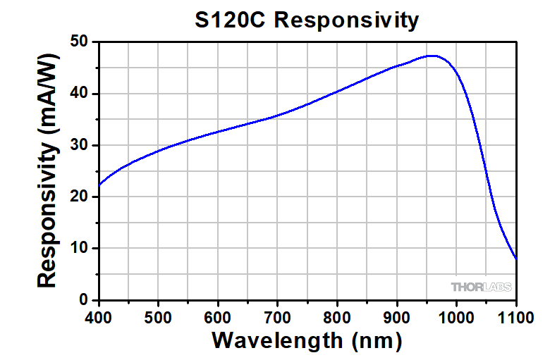
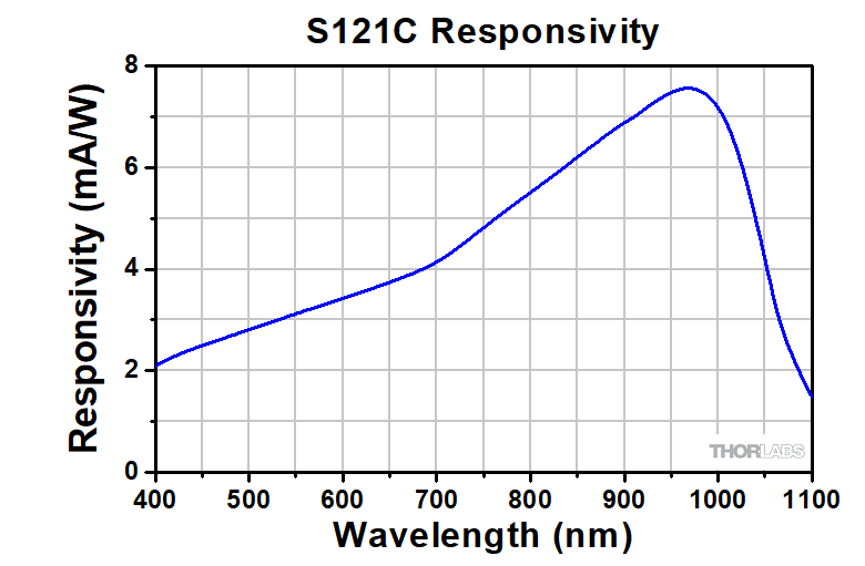
| Responsivitye (Click for Details) | 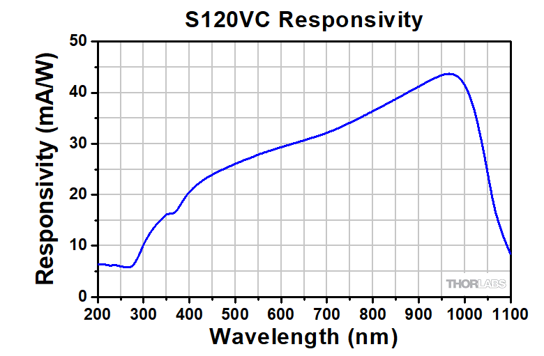 Raw Data |
 Raw Data |
 Raw Data |
 Raw Data |
Compact Slim Photodiode Sensor
| Item # | S116C | ||
|---|---|---|---|
| Technical Specs | |||
| Detector Type | Silicon Photodiode | ||
| Wavelength Range | 400 - 1100 nm | ||
| Optical Power Working Range |
20 nW - 50 mW | ||
| Max Average Power Densitya |
20 W/cm² | ||
| Max Pulse Energy | 20 µJ | ||
| Linearity | ±0.5% | ||
| Resolutionb | 1 nW | ||
| Measurement Uncertaintyc |
±3% (451 - 1000 nm) ±5% (400 - 450 nm, 1001 - 1100 nm) |
||
| Responsivityd (Click for Details) |
 Raw Data |
||
Slim Profile Photodiode Sensors: S130C Series
| Item # | S130VC | S130C | S132Ca |
|---|---|---|---|
| Technical Specs | |||
| Detector Type | Silicon Photodiode (UV Extended) |
Silicon Photodiode | Germanium Photodide |
| Wavelength Range | 200 nm - 1100 nm | 400 nm - 1100 nm | 700 nm - 1800 nmb |
| Optical Power Range (with Filter) | 500 pW - 0.5 mWc (Up to 50 mW)c |
500 pW - 5 mW (Up to 500 mW) |
5 nW - 5 mW (Up to 500 mW) |
| Max Average Power Densityd |
20 W/cm² | 10 W/cm² | |
| Max Pulse Energy | 20 µJ | ||
| Linearity | ±0.5% | ||
| Resolution | 100 pWe | 100 pWe | 1 nWf |
| Measurement Uncertaintyg |
±3% (440 - 980 nm) ±5% (400 - 439 nm) ±7% (200 - 279 nm, 981 - 1100 nm) |
±3% (440 - 980 nm) ±5% (280 - 439 nm) ±7% (981 - 1100 nm) |
±5% |
| Responsivityh (Click for Details) | Raw Data |
Raw Data |
Raw Data |
Microscope Slide Photodiode Sensors
| Item # | S170C | S171C | NS170C |
|---|---|---|---|
| Technical Specs | |||
| Detector Type | Silicon Photodiode | Second-Order Nonlinear Crystal with Silicon Photodiode |
|
| Wavelength Range | 350 - 1100 nm | 400 - 1100 nm | Laser: 780 - 1300 nm SHG: 390 - 650 nm |
| Optical Power Working Range |
10 nW - 150 mW | 1 nW - 15 mW | Laser: 0.5 - 350 mWa SHG: 10 nW - 5 mW |
| Max Average Power Densityb |
20 W/cm2 | 10 W/cm2 | N/A |
| Max Peak Power Densityc | - | - | 10 TW/cm2 |
| Max Pulse Energy | - | - | - |
| Linearity | ±0.5% | ±0.5%d | |
| Resolution | 1 nWe | 0.5 pWf | 1 nWd,e |
| Measurement Uncertainty |
±3% (440 - 980 nm)g ±5% (350 - 439 nm)g ±7% (981 - 1100 nm)g |
±3% 440 – 980 nmg,h ±5% 400 – 439 nmg,h ±7% 981 – 1100 nmg,h |
±3% (440 - 650 nm)d,i ±5% (390 - 439 nm)d,i |
| Responsivityj (Click for Details) |
 Raw Data |
 Raw Data |
 Raw Data |
Integrating Sphere Photodiode Sensors
| Item # | S140C | S142C | S142CL | S144C | S145C | S145CL | S146C | S148C | S180C |
|---|---|---|---|---|---|---|---|---|---|
| Technical Specs | |||||||||
| Detector Type | Si Photodiode | Si Photodiode with Baffle | InGaAs Photodiode | InGaAs Photodiode with Baffle | InGaAs Photodiode | Extended InGaAs Photodiode | MCT (HgCdTe) Photodiode |
||
| Wavelength Range | 350 - 1100 nm | 400 - 1100 nm | 800 - 1700 nm | 900 - 1650 nm | 1200 - 2500 nm | 2.9 µm - 5.5 µm | |||
| Optical Power Range | 1 µW - 500 mW | 1 µW - 5 W | 10 µW - 5 W | 1 µW - 500 mW | 1 µW - 3 W | 10 µW - 3 W | 10 µW - 20 W | 1 µW - 1 W | 1 µW - 3 W |
| Max Average Power Densitya |
1 kW/cm² | 2 kW/cm² | 1 kW/cm² | 2 kW/cm² | 1 kW/cm² | ||||
| Max Pulse Energy Density |
1 J/cm² | 7 J/cm² | 1 J/cm² | 7 J/cm² | 1 J/cm² | ||||
| Linearity | ±0.5% | ||||||||
| Resolutionb | 1 nW | 10 nW | 1 nW | 10 nW | 1 nW | 10 nW | |||
| Measurement Uncertaintyc,d |
±3% (440 - 980 nm) ±5% (350 - 439 nm) ±7% (981 - 1100 nm) |
±3% (440 - 980 nm) ±5% (400 - 439 nm) ±7% (981 - 1100 nm) |
±5% | ||||||
| Responsivitye (Click for Plot) |
 Raw Data |
 Raw Data |
 Raw Data |
 Raw Data |
 Raw Data |
 Raw Data |
 Raw Data |
 Raw Data |
 Raw Data |
Fiber-Coupled Photodiode Sensors: S150C Series
| Item # | S150C | S151C | S154C | S155C |
|---|---|---|---|---|
| Technical Specs | ||||
| Detector Type | Si Photodiode | InGaAs Photodiode | ||
| Wavelength Range | 350 nm - 1100 nm | 400 nm - 1100 nm | 800 nm - 1700 nm | 800 nm - 1700 nm |
| Optical Power Range | 100 pW - 5 mW (-70 dBm to 7 dBm) |
1 nW - 20 mW (-60 dBm to 13 dBm) |
100 pW - 3 mW (-70 dBm to 5 dBm) |
1 nW - 20 mW (-60 dBm to 13 dBm) |
| Max Average Power Densitya | 100 mW/cm² | 10 W/cm² | 100 mW/cm² | 10 W/cm² |
| Max Pulse Energy | 20 µJ | |||
| Linearity | ±0.5% | |||
| Resolutionb | 10 pW (-80 dBm) | 100 pW (-70 dBm) | 10 pW (-80 dBm) | 100 pW (-70 dBm) |
| Measurement Uncertaintyc | ±3% (440 - 980 nm) ±5% (350 - 439 nm) ±7% (981 - 1100 nm) |
±3% (440 - 980 nm) ±5% (400 - 439 nm) ±7% (981 - 1100 nm) |
±5% | |
| Responsivityd (Click for Details) |  Raw Data |
 Raw Data |
 Raw Data |
 Raw Data |
Sensor Connectors
D-Type Male
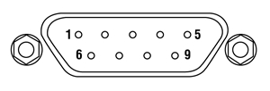
| Pin | Connection | ||
|---|---|---|---|
| S120, S140, and S150 Series, S116C, and S180C Sensors | S170C, S171C, and NS170C Sensors | S130 Series Sensors | |
| 1 | Not Used | ||
| 2 | EEPROM Data | ||
| 3 | Photodiode Anode and NTC Ground | Photodiode Anode Ground | Photodiode Anode |
| 4 | Photodiode Cathode | ||
| 5 | Not Used | ||
| 6 | EEPROM Ground | ||
| 7 | NTC | Not Used | Slider Detection |
| 8 | Not Used | ||
| 9 | Not Used | ||
Pulsed Laser Emission: Power and Energy Calculations

Determining whether emission from a pulsed laser is compatible with a device or application can require referencing parameters that are not supplied by the laser's manufacturer. When this is the case, the necessary parameters can typically be calculated from the available information. Calculating peak pulse power, average power, pulse energy, and related parameters can be necessary to achieve desired outcomes including:
- Protecting biological samples from harm.
- Measuring the pulsed laser emission without damaging photodetectors and other sensors.
- Exciting fluorescence and non-linear effects in materials.
Pulsed laser radiation parameters are illustrated in Figure 1 and described in the table. For quick reference, a list of equations is provided below. The document available for download provides this information, as well as an introduction to pulsed laser emission, an overview of relationships among the different parameters, and guidance for applying the calculations.
|
Equations: |
||||
 |
and |  |
||
 |
||||
 |
||||
 |
||||
Peak power and average power calculated from each other: |
||||
 |
and |  |
||
| Peak power calculated from average power and duty cycle*: | ||||
 |
*Duty cycle ( ) is the fraction of time during which there is laser pulse emission. ) is the fraction of time during which there is laser pulse emission. |
|||
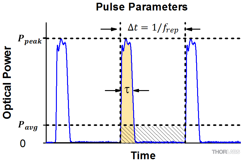
Click to Enlarge
Figure 1: Parameters used to describe pulsed laser emission are indicated in the plot (above) and described in the table (below). Pulse energy (E) is the shaded area under the pulse curve. Pulse energy is, equivalently, the area of the diagonally hashed region.
| Parameter | Symbol | Units | Description | ||
|---|---|---|---|---|---|
| Pulse Energy | E | Joules [J] | A measure of one pulse's total emission, which is the only light emitted by the laser over the entire period. The pulse energy equals the shaded area, which is equivalent to the area covered by diagonal hash marks. | ||
| Period | Δt | Seconds [s] | The amount of time between the start of one pulse and the start of the next. | ||
| Average Power | Pavg | Watts [W] | The height on the optical power axis, if the energy emitted by the pulse were uniformly spread over the entire period. | ||
| Instantaneous Power | P | Watts [W] | The optical power at a single, specific point in time. | ||
| Peak Power | Ppeak | Watts [W] | The maximum instantaneous optical power output by the laser. | ||
| Pulse Width |  |
Seconds [s] | A measure of the time between the beginning and end of the pulse, typically based on the full width half maximum (FWHM) of the pulse shape. Also called pulse duration. | ||
| Repetition Rate | frep | Hertz [Hz] | The frequency with which pulses are emitted. Equal to the reciprocal of the period. | ||
Example Calculation:
Is it safe to use a detector with a specified maximum peak optical input power of 75 mW to measure the following pulsed laser emission?
- Average Power: 1 mW
- Repetition Rate: 85 MHz
- Pulse Width: 10 fs
The energy per pulse:

seems low, but the peak pulse power is:

It is not safe to use the detector to measure this pulsed laser emission, since the peak power of the pulses is >5 orders of magnitude higher than the detector's maximum peak optical input power.
Thorlabs offers a wide selection of power and energy meter consoles and interfaces for operating our power and energy sensors. Key specifications of all of our power meter consoles and interfaces are presented below to help you decide which device is best for your application. We also offer self-contained wireless power meters and compact USB power meters.
When used with our C-series sensors, Thorlabs' power meter consoles and interfaces recognize the type of connected sensor and measure the current or voltage as appropriate. Our C-series sensors have responsivity calibration data stored in their connectors. The console will read out the responsivity value for the user-entered wavelength and calculate a power or energy reading.
- Photodiode sensors deliver a current that depends on the input optical power and the wavelength. The current is fed into a transimpedance amplifier, which outputs a voltage proportional to the input current. The photodiode's responsivity is wavelength dependent, so the correct wavelength must be entered into the console for an accurate power reading. The console reads out the responsivity for this wavelength from the connected sensor and calculates the optical power from the measured photocurrent.
- Thermal sensors deliver a voltage proportional to the input optical power. Based on the measured sensor output voltage and the sensor's responsivity, the console will calculate the incident optical power.
- Energy sensors are based on the pyroelectric effect. They deliver a voltage peak proportional to the pulse energy. If an energy sensor is recognized, the console will use a peak voltage detector and the pulse energy will be calculated from the sensor's responsivity.
The consoles and interfaces are also capable of providing a readout of the current or voltage delivered by the sensor. Select models also feature an analog output.
Consoles
| Item # | PM100A | PM100D | PM400 | PM5020 |
|---|---|---|---|---|
| (Click Photo to Enlarge) | 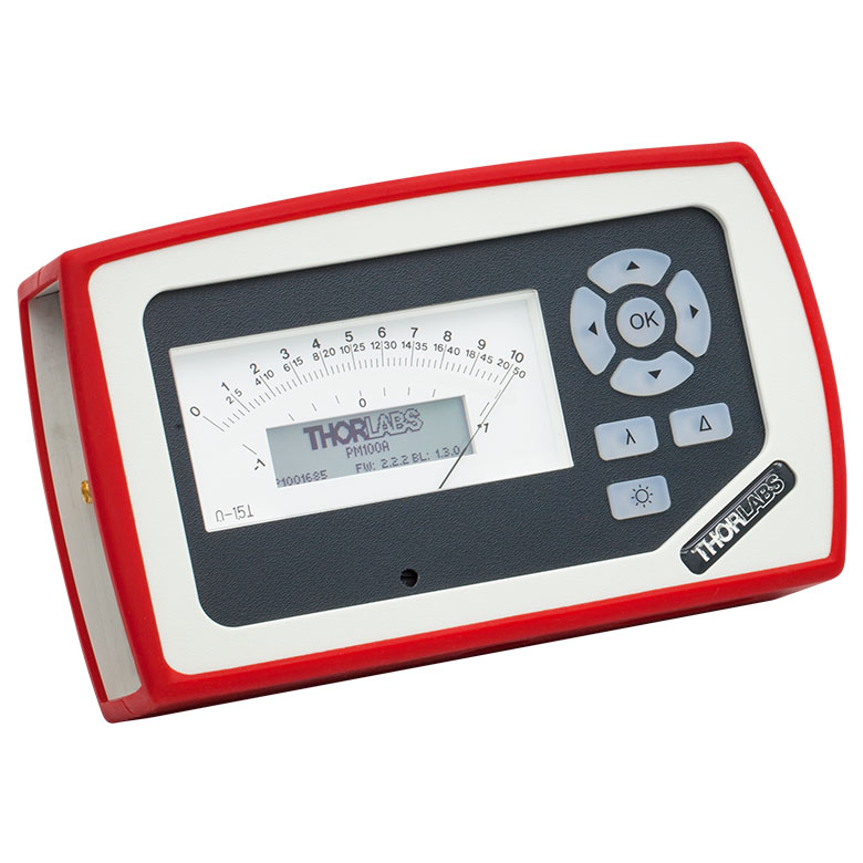 |
 |
 |
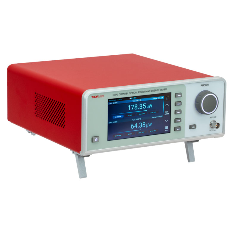 |
| Key Features | Analog Power Measurements | Digital Power and Energy Measurements | Digital Power and Energy Measurements, Touchscreen Control | Dual Channel |
| Compatible Sensors | Photodiode and Thermal Power | Photodiode Power, Thermal Power, and Pyroelectric Energya | Photodiode Power, Thermal Power, Thermal Power and Position, and Pyroelectric Energya | Photodiode Power, Thermal Power, Thermal Power and Position, and Pyroelectric Energy |
| Housing Dimensions (H x W x D) |
7.24" x 4.29" x 1.61" (184 mm x 109 mm x 41 mm) |
7.09" x 4.13" x 1.50" (180 mm x 105 mm x 38 mm) |
5.35" x 3.78" x 1.16" (136.0 mm x 96.0 mm x 29.5 mm) |
9.97" x 4.35" x 11.56" (253.2 mm x 110.6 mm x 293.6 mm) |
| Channels | 1 | 2 | ||
| External Temperature Sensor Input (Sensor not Included) | - | - | Readout and Record Temperature Over Time | Readout and Record Temperature Over Time |
| External Humidity Sensor Input (Sensor not Included) | - | - | Readout and Record Humidity Over Time | Readout and Record Humidity Over Time |
| Input/Output Ports | - | 4 GPIO, Programmable | 4 Configurable Digital I/O Channels | |
| Shutter Control | - | - | - | Support for SH05R(/M) or SH1(/M) Optical Shutter with Interlock Input |
| Fan Control | - | - | - | |
| Source Spectral Correction | - | - | ||
| Attenuation Correction | - | - | ||
| External Trigger Input | - | - | - | |
| Display | ||||
| Type | Mechanical Needle and LCD Display with Digital Readout | 320 x 240 Pixel Backlit Graphical LCD Display | Protected Capacitive Touchscreen with Color Display | |
| Dimensions | Digital: 1.9" x 0.5" (48.2 mm x 13.2 mm) Analog: 3.54" x 1.65" (90.0 mm x 42.0 mm) |
3.17" x 2.36" (81.4 mm x 61.0 mm) |
3.7" x 2.1" (95 mm x 54 mm) |
4.32" x 2.43" (109.7 mm x 61.6 mm) |
| Refresh Rate | 20 Hz | 10 Hz (Numerical) 25 Hz (Analog Simulation) |
25 Hz | |
| Measurement Viewsb | ||||
| Numerical | ||||
| Mechanical Analog Needle | - | - | - | |
| Simulated Analog Needle | - | |||
| Bar Graph | - | |||
| Trend Graph | - | |||
| Histogram | - | - | - | |
| Statistics | ||||
| Memory | ||||
| Type | - | SD Card | NAND Flash | SD Card |
| Size | - | 2 GB | 4 GB | 8 GB |
| Power | ||||
| Battery | LiPo 3.7 V 1300 mAh | LiPo 3.7 V 2600 mAh | - | |
| External | 5 VDC via USB or Included AC Adapter | 5 VDC via USB | Line Voltage: 100 - 240 V | |


| Posted Comments: | |
user
(posted 2024-05-18 12:27:11.367) I was excited to find this this item, because it is really useful to mount a 10mm cube or prism e.g. on a rotation mount in a compact way. It could be added to the appropriate pages, although a nylon tipped screw would be better in that case.
Also there could be versions for the different cube sizes (5mm / 12.7mm). hkarpenko
(posted 2024-05-21 10:57:14.0) Dear Julian,
thank you for your kind feedback.
This item was initially intented to be used to attach the slim photodiode sensor S116C to other components with 1 inch threadings. For mounting beam splitter cubes we have other different mounting options. However, it´s a good idea to use this quite small adapter SM05A29 to mount cubes with dimensions of 10mm. I will forward this to our development team to work on further design options and maybe adapt this idea to mount cubes with other dimensions as mentioned by you. Seongjae Lee
(posted 2024-02-13 16:51:03.627) Dear Thorlabs,
Recently, I purchased S122C through BM Laser solution in South Korea.
I connected S122C to PM101 and measured output from 905 nm pulsed LD.
However, we found that the output value changes significantly by measuring setting especially "Attenuation" "Range"
Also, it shows very different value with S405C which we purchased previously.
I'm not sure with setting of S122C guarantees reliable average power of the input light.
The pulsed duration, repetition rate, average power of the 905 nm pulsed LD output is 100 ns, 1 kHz, and 12.5 mW.
Can you tell me how to set up the S122C and how to measure the reliable optical power? hkarpenko
(posted 2024-02-14 11:50:49.0) Dear customer,
thank you very much for your feedback. Measuring pulsed laser sources with photodiode sensors can be challenging depending on the laser parameters. Especially the peak power of the laser can damage the sensor or the repetition rate is too low, thus the sensor is fast enough to follow some pulses. I will contact you directly to discuss this further with you. 諒一 芝山
(posted 2023-11-01 11:35:58.37) 同製品の再校正を検討しております。
メーカーでの校正を依頼させて頂く場合、校正依頼書等の文書作成は必要でしょうか?
(*オフィール社では修理・構成作業依頼書の送付が必要であったため) fmortaheb
(posted 2023-11-02 05:03:03.0) Thank you very much for contacting us. An application engineer from our team in Japan will discuss this directly with you. Marie Zandi
(posted 2023-08-24 16:07:02.443) Hi,
I would like to measure the average power of a ns pulsed laser (fiber coupled). I have access to the S145C integrating sphere and would like to know if I can use it for this. I saw some of your posted comments on this feedback page, and it looks like a thermal sensor might be better for an accurate power measurements. The pulsed laser specs are: 30ns in pulse length, repetition rate of 10kHz, average power of 100mW, peak power of 330W. Could you help me with this? Thank you. dpossin
(posted 2023-08-28 09:14:49.0) Dear Marie,
Thank you for your feedback. Your intendet application does not work with photodiodes for two reasons:
The peak pulse power will saturate the photodiode
The duty cycle is way too low in order to perform average power measurement
Your are right by suggesting that a thermal sensor will be a much better choice.
I reach out to you in order to provide more detailed information. user
(posted 2023-08-24 16:05:59.117) Hi,
I would like to measure the average power of a ns pulsed laser (fiber coupled). I have access to the S145C integrating sphere and would like to know if I can use it for this. I saw some of your posted comments on this feedback page, and it looks like a thermal sensor might be better for an accurate power measurements. The pulsed laser specs are: 30ns in pulse length, repetition rate of 10kHz, average power of 100mW, peak power of 330W. Could you help me with this? Thank you. Miao Zhu
(posted 2023-08-08 18:19:58.593) Hello,
It seems the power meter PM100D does not display the the correct power when using S112C (or S145C). We tried on two different PM100D units. Is there a power meter which can read S112C and S145C?
Thank you. hchow
(posted 2023-08-10 09:26:08.0) Dear Miao Zhu, thank you for your feedback. I will personally reach out to you to provide assistance. Thank you. 申 钰铜
(posted 2023-07-26 10:12:35.253) 你好,我的s130c的滤光片损坏了,请问可以更换配件么?麻烦提供一下型号 hchow
(posted 2023-07-27 03:44:46.0) 我们可以为您的S130C更换过滤器,但是,您必须联系我们的Thorlabs中国公司进行RMA。 sanghyun Choi
(posted 2023-06-29 20:02:37.613) I have PM200 meter.
Is this sensor compatible with PM200 meter?
Best regards
Sanghyun wskopalik
(posted 2023-06-30 09:36:55.0) Thank you very much for your feedback!
Yes, the PM200 is compatible with the S122C.
I will contact you directly to provide further assistance. user
(posted 2023-04-17 21:45:16.387) What is the maximum peak pulse power for the S120C photodiode sensor? I'm asking becuase the specs contain only information about the max. average power density and the max. pulse energy. hchow
(posted 2023-04-18 06:39:18.0) Dear User, thank you for your feedback. So long as your peak pulse power doesn't exceed the maximum average power density, 20 W/cm², or the maximum pulse energy, 20 µJ, your laser should be fine to use.
For continuous wave (CW) sources, the maximum average power density is equivalent to the peak power density, while for pulsed laser sources this value is calculated from the time-averaged power and beam profile. The maximum average power density is determined by the total energy deposited, so the instantaneous power can be higher, as long as the maximum pulse energy is not exceeded. Junyu Li
(posted 2023-01-05 16:47:23.097) I bought an S140C probe with serial number 220601140, and the number of valid digits of the responsitivity data on the included test report is only 3 digits, is there any way to get the 4-digit significant digit data? (Is it okay to use the PM400) Because the responsitivity curve attached to your website has four significant digits. hchow
(posted 2023-01-05 05:07:49.0) Dear Mr. Li, thank you for your feedback. I will personally reach out to you to provide the necessary information you seek. Thank you. Vincent Mazoyer
(posted 2022-11-08 14:40:08.72) Dear Sir or Madam,
The CAD model is wrong: the mounting holes are too close to the sensing area in the model; do not match the drawings. Also, the model shows S130C instead of S130VC; filename says S130VC nevertheless.
Sincerely yours,
Vincent Mazoyer hchow
(posted 2022-11-09 03:20:06.0) Dear Mr. Mazoyer, thank you for your feedback. I will personally reach out to you to discuss this matter. Thank you very much. D M
(posted 2022-10-11 12:46:45.26) Hello, is it possible to provide a photodiode power sensor for wavelengths between 1900nm and 2000nm? hchow
(posted 2022-10-11 11:04:14.0) Hi, thank you very much for your enquiry. We do indeed have a photodiode power sensor capable of detecting between 1900 nm to 2000 nm and it is our S148C. The S148C is efficient in detecting light between 1200 nm to 2500 nm. I will personally reach out to you to provide more information about the specifications of this photodiode power sensor. Thanks again. Alan Lin
(posted 2022-09-27 19:21:39.45) Hi,
Good day,
Do you have any material about power measure response on different incident angle for pm160-121 detector?
thanks, wskopalik
(posted 2022-09-28 03:11:34.0) Thank you very much for your feedback!
We make the calibration of these sensors with a beam which is incident on the sensor perpendicularly. So for best accuracy it is recommended to use these sensors at an angle of incidence which is as close to perpendicular as possible. For other angles, deviations of a couple of percent in the power readings are possible.
I will contact you directly to provide further information. Juan de Dios Marin de Espinosa Romero
(posted 2022-09-26 06:39:05.833) good morning, my name es Juan Marin , Manager of labortecnic S.A. company from Granada Spain ,
Dedicate to distribution instrument scientific for Center for investigation, I need ofert of your reference ;
S121C - Sensor de potencia de fotodiodo estándar, Si, 400 - 1100 nm, 500 mW with transport to Granada Spain
dates for facturarion
labortecnic S.A.
c/ fray Luis de Leon, 3, 18004 Granada
CIF A18512582
TFNO 958294402
jmarin@labortrecnic.es H K
(posted 2022-09-19 15:44:22.1) Hello. I would like to ask a question power range of S120C.
In the given specsheet, the lower boundary of power range is 50 nW.
In my experience, it seems that power of less than 50 nW can be measured under the experimental conditions with good sealing.
Can you explain what the 50 nW value means? wskopalik
(posted 2022-09-19 04:30:58.0) Thank you very much for your feedback!
The lower limit of the power range is mainly determined by dark current in the photodiode and noise in the electronics. The 50 nW are what we can safely specify for this sensor type. It is however not a hard limit. Depending on the batch of the photodiode and on the measurement settings, you might also be able to measure power levels a little below 50 nW.
I will contact you directly to provide further assistance. A. T.
(posted 2022-07-25 08:03:38.09) Hi, I would like to measure a 40W (max) signal @1000nm. Note that it is a 50ms pulse, not CW, and we would use the PM103A power meter.
Would it be possible to use a S146C integrating sphere at this power and this wavelength?
I assume that the 20W limit of the sphere is the non-linearity of the sensor above 20W. Considering that the sensor is mush less responsive @1000nm, it would therefore be possible to go up to 40W.
Thank you. dpossin
(posted 2022-07-26 10:49:11.0) Dear Antonin,
Thank you for your inquiry. We do not specify our powermeters beyond the specified powerrange. Please also note that integrating sphere based sensors are not very well suited for pulsed lasers as the sphere broadens the pulse. At 40W most probably the sensor will saturate or even gets damaged at a power level of 40W. I am reaching out to you in order to discuss this in more detail. user
(posted 2022-07-11 08:06:09.287) Hi, using the S145C integrating sphere. In addition to my last question, what is the max. incident angle of a beam in the sphere aperture? dpossin
(posted 2022-07-13 05:58:49.0) Dear Customer,
Thank you for your feedback. This is an response to both of your questions. First of all the linearity is the relative measurement accuracy based on the resolution the photocurrent can be measured by the powermeter console. The measurement uncertainty in contrast is the absolute measurement accuracy based on the tolerance on the reference photodiode and the uncertainty in the calibration setup. user
(posted 2022-07-11 06:13:30.46) Hi, using the S145C integrating sphere.
What do you mean by linearity of +- 0,5 % and a measurement uncertainty of +- 5 %. Can you explain further?
thank you in advance. Eric Lentz
(posted 2022-06-06 10:50:16.94) Hello. It would be great if there was an adaptor to the S142C power sensor with the threaded plate still on. We are switching between the S120-FC and the S140-BFA so we leave the threaded plate on the power sensor and made a rough adaptor for the S140-BFA to the threaded plate. Thanks dpossin
(posted 2022-06-08 05:48:34.0) Dear Eric,
Thank you for your feedback. I am reaching out to you in order to discuss possible options. Zhenpu Zhang
(posted 2022-05-10 02:26:07.603) Hi, I am wondering what the communication protocol between the sensor head and the console is for transmitting the EEPROM Data?
Is it through UART? dpossin
(posted 2022-05-10 09:34:54.0) Dear Zhenpu,
Thank you for your inquiry. We are using 1-wire to communicate between the EEPROM and our powermeter consoles. user
(posted 2022-03-08 16:11:04.957) When using the S120C at 1064 nm, the unit will report much higher power than the 50 mW engraved on the back. This doesn't seem unreasonable as the QE is so different from the maximum QE value (at a different wavelength).
However, is the response nonlinear at these intensities for this wavelength?
Thanks for your time! soswald
(posted 2022-03-14 06:50:55.0) Dear David,
thank you for your feedback. I have reached out to you directly to discuss your measurements in more detail. Siva Natrajan
(posted 2021-07-20 21:22:24.053) I have an S155C detector. I would like to know the Integration time & bandwidth of this detector MKiess
(posted 2021-07-26 05:06:18.0) Dear Siva, thank you very much for your inquiry. The S155C is an InGaAs photodiode, integrated into a C-Type connector Design, compatible with our power meter consoles. The photodiode only generates a current proportional to the light power reaching the active sensor area. The integration time is therefore given by the measurement console. The rise time of the diode itself is in the nanosecond range. I have contacted you directly to discuss further details in combination with your measurement console. tseng yaohsin
(posted 2021-06-17 17:16:01.31) Hi Thorlabs,
Could you share the raw data of the responsibility for this detector to me ?
The csv or excel should be fine.
Thanks. cdolbashian
(posted 2021-06-22 05:09:37.0) Thank you for reaching out to us at Thorlabs! All of our raw data can be found on the product family page in close proximity to the individual product listing: in this case on the table where the S148C specs are listed. I have contacted you directly with the data you requested, and the specific method of locating it on the web page. Atefeh Ajami
(posted 2021-06-16 20:21:13.847) I want to calculate the uncertainty of the power meter
I wanted to know how? And what quantities are effective in this uncertainty? soswald
(posted 2021-06-18 09:49:46.0) Dear Atefeh,
thank you for your feedback. The measurement uncertainty of the S120VC is wavelength dependent:
±3% (440 - 980 nm)
±5% (280 - 439 nm)
±7% (200 - 279 nm, 981 - 1100 nm)
This uncertainty takes several uncertainties of our calibration setup into account such as reference diode uncertainty, wavelength set and bandpass uncertainty, temperature uncertainty and uncertainties of the electric circuit used to measure the photocurrent during calibration. Chang Jeremy
(posted 2020-11-06 00:31:58.187) Hello
I want to understand how to calculate the standard deviation in the power meter. I did a program to control PM100D and I calculated standard deviation by calculating mean power with common method on Wiki;however, the value I calculate is 10 times than the value Power meter showed. Please give a hand. Thanks!
Best, Jeremy dpossin
(posted 2020-11-10 10:47:13.0) Dear Jeremy,
Thank you for your feedback. The standard deviation is calculated on the fly. I am reaching out to you in order to provide the relevant algorithm we use to calculate the standard deviation. user
(posted 2020-10-17 10:14:25.98) I have a photodiode S132C, I measure the photocurrent by transimpedance amplifier and next lock-in at 0V bias. I need to determine the power density of the light out from the monochromator. What area do I need to take to right calculate power density, the active detector area, or beam size? MKiess
(posted 2020-10-19 10:38:08.0) Thank you very much for your inquiry. To measure the power density, you should use the beam size incident on the sensor. pao chen
(posted 2020-09-14 13:37:16.15) I have 2 units of S120VC working with 2 PM100D meters.
However, I leant that the reading of S120VC is about 55%~ 60% of that measured by various SiC sensors at 265nm and 275nm.
It is significant to determine which reading is correct in UV measurement. Can you please provie your opinion on this matter? MKiess
(posted 2020-09-15 04:55:14.0) Thank you very much fo your inquiry. If the sensor is currently calibrated and the wavelength and power range settings on the Power Meter are correct, the S120VC should have a maximum measurement uncertainty of ±7% in this wavelength range.
I have contacted you directly to discuss your measurement results in detail. Michal Pelach
(posted 2020-07-09 08:41:26.2) Is it possible to get sensor calibration data at 785 nm? MKiess
(posted 2020-07-10 08:29:39.0) This is a response from Michael at Thorlabs. Each S120VC is individually calibrated before delivery. Therefore the values are slightly different for each sensor. The typical value for the responsivity of the S120VC at 785nm is 35.69mA/W. I have contacted you directly to discuss the exact details for your sensor. li bo
(posted 2020-06-16 21:01:29.83) 积分球传感器里面脏了,怎么清理呢 wskopalik
(posted 2020-06-17 10:26:09.0) This is a response from Wolfgang at Thorlabs. Thank you very much for your inquiry.
The question is how integrating sphere sensors like the S142C can be cleaned. The housing may be cleaned by wiping with a soft damp cloth. The integrating sphere inner surface however cannot be cleaned and should not be touched. You can gently blow off any debris using compressed air. If this does not remove all the dirt or dust in the sphere, the sphere will probably need to be exchanged so you would need to send the sensor in for a repair.
Our Tech Support team in China will reach out to you directly. 達也 真藤
(posted 2020-04-16 21:52:55.94) 積分球パワーセンサS146Cについて、スペックシートにMax Pulse Energy Density 7 J/cm²との記載があったが、これはレーザの1周期中に放射される1パルスの全放射エネルギーを意味している、という解釈で良いか確認させて頂きたい。 MKiess
(posted 2020-04-20 05:26:42.0) お問合せをありがとうございました。ソーラボジャパンの技術サポートから直接回答をいたします。 xinxin peng
(posted 2020-04-10 16:55:13.01) 应用太有限,我们希望底部有个M4的螺孔,用支柱用于各种光路系统中,希望采纳。 YLohia
(posted 2020-04-10 09:40:01.0) Thank you for contacting Thorlabs. An applications engineer from our Tech Support team in China will reach out to you directly. user
(posted 2020-02-25 10:34:47.983) Hi,
I'm using the S130C to measure the power of a beam, either collimated, divergent or focused. Is it normal to have different power values depending on whether the beam covers a large fraction of the detector's surface (case of collimated beam) or covers a small surface (focused beam)?
Thank you for your help
Best nreusch
(posted 2020-02-27 09:02:08.0) This is a response from Nicola at Thorlabs. Thank you very much for your feedback! S130C comes with a Si photodiode. Photodiodes in general are sensitive to the angle of incidence. So for focused and divergent beams, you will always have parts of the beam that will not hit the sensor at a right angle, which will affect the measurement. Photodiode sensors will also not show a completely uniform response over their active area. Therefore, the specified measurement uncertainty is only valid for beam diameters larger than 1 mm. You should also take care to not overfill the sensor with a divergent beam. We will contact you directly to discuss your specific application in more detail. Matthew Kirchner
(posted 2019-11-25 13:24:07.727) Hi, does the S142C correct for temperature dependence of the Si photodiode responsivity? dpossin
(posted 2019-11-27 08:43:20.0) Dear Customer,
Thank you for your feedback. The S142C does not compensate temperature effects of the sensor automatically. However it is possible to compensate
the temperature dependent dark current with our powermeter consoles. I am reaching out to you to provide further information on that. user
(posted 2019-11-15 12:57:48.94) Dear Thorlabs,
We are considering ordering one of your products to measure the average power of a scanned pulsed laser, that reaches an aperture of a few mm, with the following parameters:
» Beam width: 1 mm
» Wavelength: 1,5 micron
» Pulse energy: 1 micro-Joule
» Pulse duration: 1 nW
The pulse train incident on the opening depends on its diameter as well as the scanning parameters:
» Repetition frequency: minimum 10 Hz (frame rate); maximum 1MHz (pulse repetition rate)
» Average power on aperture: typical 10 mW; minimum 10 micro-W; maximum 1 W (static beam).
Which kind of power meter do you recommend for the described application: a photo-diode/integrating sphere or a thermopile?
Sincerely,
Flávio Ferreira
-----
University of Minho
Department of Physics MKiess
(posted 2019-11-18 06:12:44.0) This is a response from Michael at Thorlabs. Thank you for the inquiry. Depending on the pulse duration, repetition rate, laser power and the general conditions of your application, a thermal sensor or a photodiode sensor may be suitable for you. In order to be able to use this optimally, different conditions have to be fulfilled depending on the sensor type. Details can be found under the following link:
https://www.thorlabs.de/newgrouppage9.cfm?objectgroup_id=6188&tabname=%20Sensor%20Selection
I contacted you directly to discuss further details and select the most suitable sensor together with you. Karim Elkhouly
(posted 2019-10-23 07:39:14.07) I am considering using an integrated sphere for calibrated EQE measurements of LEDs. I am wondering what is the fundamental difference between standard power meters like the S120VC and ones for integrating spheres. Especially that the minimum detectable power is much higher in the latter option. Can I use S120VC with integrating sphere for example ? MKiess
(posted 2019-10-28 11:09:54.0) This is a response from Michael at Thorlabs. Thank you for the inquiry. The radiation scattered in the integrating sphere is almost ideally diffuse over the specified spectrum. This allows on the one hand to measure a photometric standard and on the other hand to measure the power or the total radiation flux of different light sources, independent of beam uniformity, divergence, beam shape and entrance angle, making them excellent for use with fiber sources and off-axis free space sources.
Due to the diffusivity, the power range is also higher than that of the sensors with which the radiation is measured directly, such as the S120VC.
These are therefore better suited for measurements of collimated beams with small powers.
I have contacted you directly to select the most suitable sensor for your application together. Andrey Kuznetsov
(posted 2019-07-12 15:15:12.757) S12X series photodiodes have a poorly modeled solidworks file, can you update the model to reflect the internal size and position of the photodiode. While the aperture is 9.5mm, the aperture appears to be 3.3mm from the photodiode based on PDF drawing. This means that when measuring divergent light, if the photodiode is not large enough to collect all the light passing through the 9.5mm aperture then the measurement will be wrong. A +-45 degree light passing through a 9.5mm aperture with detector at 3.3mm away from aperture will expand the minimum radius of the photodiode by 3.3mm to 16.1mm diameter. wskopalik
(posted 2019-07-23 10:33:46.0) This is a response from Wolfgang at Thorlabs. Thank you very much for your inquiry!
It is generally not recommended to measure strongly divergent beams with a S12X series sensor. One reason is - as you have mentioned - that it is difficult to make sure that all the light is collected by the photodiode. In addition, photodiodes also show a dependence of the responsivity with respect to the angle of incidence. So these sensors are not ideal.
For a divergent beam e.g. the sensors of the S14X series would be much more suitable. These have an integrating sphere which makes the collection of the light easier and which also ensures that the light is shining on the photodiode perpendicularly.
I will contact you directly regarding these sensors and the drawings. Andrey Kuznetsov
(posted 2019-07-09 11:39:03.727) Please update the Drawing for S122C, it points to a PDF that includes other photodiodes and does not explicitly mention S122C anywhere. mmcclure
(posted 2019-07-11 08:16:35.0) Hello, thank you for bringing this to our attention. We have added the S122C-specific PDF drawing on the webpage. user
(posted 2019-07-03 19:19:41.117) Can Thorlabs improve the calibration uncertainty from 3% to 1%? This is the major sticking point when considering Thorlabs photodiodes for use in precise calibration systems where 0.5% errors matter. dpossin
(posted 2019-07-05 10:34:27.0) Dear customer,
Thank you for your feedback. Unfortunately we can not specify an uncertainty of 1% over the full spectral range. Our references are calibrated by PTB or NIST and have an uncertainty of 0.3% up to 1.5% with respect to the wavelength. If we take into account the expanded uncertainty trough the reference and the calibration Setup, we get an Overall uncertainty of 2% for silica based sensors and 3% for germanium based sensors. user
(posted 2019-06-19 11:51:29.203) Could you use the same ND filter that you used for the S121C Silicon head so as to allow this Ge head to measure up to 500mW?
We could really use a Ge head that measures up to 500 mW. wskopalik
(posted 2019-06-21 09:57:17.0) This is a response from Wolfgang at Thorlabs. Thank you very much for your inquiry!
We should be able to offer this as a custom version. I will contact you directly regarding your requirements. Alternatively, you could also use the S132C which has a Ge photodiode and can measure up to 500mW or also the S144C which has an InGaAs photodiode. On the S144C the wavelength range is slightly different, but you can also measure up to 500mW. user
(posted 2019-05-01 13:02:36.09) The strain relief for the cable exiting the 9 way D connector head-shell is inadequate. From active use in the lab, the flexing has broken the outer sheath and is putting strain onto the inner conductors. I have had to effect an interim repair - can send you pics if you contact me. wskopalik
(posted 2019-05-02 07:47:21.0) This is a response from Wolfgang at Thorlabs. Thank you very much for your feedback!
I'm sorry to hear about this issue with your sensor. I will contact you directly so you can send me pictures of the defective cable. I'm sure that we will find a good solution in this case. Fabian Röser
(posted 2019-04-09 04:02:07.897) Dear Sir/Madam,
when measuring the average power of a pulsed system with a S145C integrating sphere, I noticed that the response is strongly dependend on the actual repetition rate of the pulse train. Measuring at 50kHz shows only a fraction of the average power.
Could you please specify the repetition frequency band of quasi-cw signals in which these Sensors can be used? Also, can they be modified to work with repetion rates in the kHz range?
Thanks in advance nreusch
(posted 2019-04-16 06:16:03.0) This is a response from Nicola at Thorlabs. Thank you for your inquiry. The behavior that you observed results from the combination of the rise and fall times of the photodiode as well as the electronic bandwidths of amplifiers and converters of the readout circuits. I recommend using a thermal power head in order to measure the average power of a pulsed system. I will contact you directly to discuss different options for your application. yongqi.shi
(posted 2019-01-30 09:26:44.323) Dear Sir/Madam, I'm using S130C power sensor. When I use the filter to measure the optical power around 28mW, I found that the there's always a 15% to 20% deviation when change the incident angle of the beam from -20 deg to 20 deg. What would be the reason and how to get a more precise measurement? Thank you in advance. wskopalik
(posted 2019-02-04 10:51:28.0) This is a response from Wolfgang at Thorlabs. Thank you very much for your inquiry!
The ideal case for photodiode sensors is if the beam hits the photodiode and the filter perpendicularly. This is how the sensors are calibrated so the accuracy is the highest in this case. The responsivity of photodiodes as well as the attenuation of filters depend on the angle of incidence. This means that the displayed power readings will change if the angle of incidence is changed. Thermal power sensors are more suitable for applications in which the angle changes because they have much less dependence on the angle of incidence.
I will contact you directly to provide further assistance. user
(posted 2019-01-23 13:11:44.777) Dear Sir. Is it possible to use two Powermeter S121 at the same time with the same software on PC?Now I only can choose one USB-connection at the software. wskopalik
(posted 2019-04-05 11:02:09.0) This is a response from Wolfgang at Thorlabs. Thank you very much for your feedback!
Yes, it is possible to operate up to eight power meters simultaneously in the power meter software. You would need a power meter for each sensor which you want to operate in the software. Maybe there is an issue with one of these connections. It is however hard to tell without further details.
Unfortunately, you didn't leave any contact details in the feedback so I cannot contact you directly. Please feel free to contact me any time at europe@thorlabs.com. abc124771
(posted 2019-01-21 17:01:19.24) What does 'max. avg. power density' of 20W/cm2 signify? Does it mean it can withstand 20W? Or is the max. power it can withstand given by the range which is 500mW for S130C? swick
(posted 2019-01-25 04:11:07.0) This is a response from Sebastian at Thorlabs. Thank you for the inquiry. The max. average power density represents the damage threshold of the sensor. dietrich
(posted 2018-12-13 10:50:27.293) Dear, Sir. We want to measure light which is more or less broadband with a wavelength of 1900 to 2300 nm in the power range from 1 mW to 1 W. Unfortunaly your detector S148C has in this area strong nonlinearities. Is it possible that you replace the build in photo diode with a different one like extended InGaAs with a cutoff wavelength of 2.6 μm?
With best Regards Christian Markus Dietrich nreusch
(posted 2018-12-19 02:22:17.0) This is a response from Nicola at Thorlabs. Thank you very much for your inquiry. Yes, we can offer customized versions of our integration spheres with different diodes. I will contact you directly to discuss further details. aSadykov
(posted 2018-07-17 09:55:31.477) Dear, Sir.
Datasheet for S122C include parameter -"Measurement Uncertainty" which is equal to "+/- 5%".
and collibration has been made in accordiance with NIST.
I'd like to make clear "Measuremet Uncertainty" in data sheet is "Standard measurement uncertainty" or something else.
https://www.nist.gov/itl/sed/topic-areas/measurement-uncertainty
With best Reguards
Andrey Sadykov nreusch
(posted 2018-07-20 10:17:17.0) This is a response from Nicola at Thorlabs. Thank you for your inquiry! Your assumption is correct. The "Measurement Uncertainty" specification corresponds to the "Standard Measurement Uncertainty" as defined by NIST. jhamilton
(posted 2018-05-30 13:19:00.957) Can you please provide me with operational temperature range for the S122. Can you also provide me with RoHS status.
Thank you mvonsivers
(posted 2018-06-05 05:15:09.0) This is a response from Moritz at Thorlabs. Thank you for your inquiry. The RoHS declaration can be found by clicking on the red document button next to the product number. The sensors are calibrated at room temperature, operating them at other temperatures will reduce the accuracy of the measurement. cyprien.lanthermann
(posted 2018-04-19 16:09:31.14) Hi, could you tell me the accuracy on the diameter of the photodiode?
Thanks,
Lanthermann Cyprien swick
(posted 2018-04-27 04:16:20.0) This is a response from Sebastian at Thorlabs. Thank you for the inquiry. The Photodiode used in S132C has an active area of 9.7 mm x 9.7 mm and the clear aperture is 9.5 mm (+/- 0.02 mm). user
(posted 2018-01-15 09:28:55.797) Hi, is the sensor head is well shielded against ESD? or should the user be grounded while connecting it to the console?
Thanks, mvonsivers
(posted 2018-01-16 08:19:12.0) This is a response from Moritz at Thorlabs. Thank you for your inquiry.
As the photodiode is mounted inside the sensor housing it is generally not as ESD sensitive as a bare photodiode. Nevertheless, the user must use handling procedures that prevent any electro static discharges or other voltage surges when handling or using these devices. mailfert
(posted 2017-11-17 13:28:07.937) Hi,
The glass window in front of my detector is broken, not the sensor.
This window is removable so I'm trying to know if we can just buy the window without the complete sensor.Best regards. wskopalik
(posted 2017-11-22 04:41:47.0) This is a response from Wolfgang at Thorlabs. Thank you very much for your inquiry!
We don't recommend to exchange the ND filter window on these sensors yourself because the calibration is only valid with the filter which was mounted during the calibration. There are slight differences from filter to filter. So if the filter needs to be exchanged, the sensor needs to be recalibrated after the exchange. This can only be done in our facilities.
I will contact you directly to discuss the further proceedings. lebouquj
(posted 2017-10-11 16:47:30.52) Hi, I am interested by detection in 1200-2500nm spectral range, with minimum flux 10nW. This spectral range is only made available in Integrating-Sphere design (S148C), thus is poorly sensitive (1uW). Would it be possible to have the sensor of S148C but packaged as the S132C (which has 5nW resolution) ? Thanks wskopalik
(posted 2017-10-16 05:06:35.0) This is a response from Wolfgang at Thorlabs. Thank you very much for your inquiry!
The photodiode used in the S148C which can cover this spectral range only has an active area of 1 mm in diameter. So with our sensor designs this photodiode only works in an integrating sphere. E.g. for the S132C design, the active area would need to be 9.7 mm x 9.7 mm in size.
Our R&D is looking into the possibility of offering a special sensor for your requirements and I will contact you directly about this. storm.liao
(posted 2017-09-15 09:57:27.58) Would you please let me know the active area of S122C? tcampbell
(posted 2017-09-15 11:18:45.0) Hello, thank you for contacting Thorlabs. The active detector area of the S122C is 9.7 mm x 9.7 mm. This value can be found on the spec sheet, but we will try to make it more visible on the website. jv
(posted 2017-09-02 08:43:39.217) It would be great to have an adapter that allows the power detector to measure the output from an FC bulkhead (female). So the adapter would have a hole that fits over the threads of the bulkhead to measure power output. We use this ALL THE TIME for calibrating our products. Could also extend the idea to other bulkhead connectors. Thanks, Janis mvonsivers
(posted 2017-09-04 04:24:17.0) This is a response from Moritz at Thorlabs. Thank you for your feedback. I agree that such an adapter would be useful and I will gladly forward your suggestion to our R&D department. At the moment you can still measure the output by using a short patch cable which can be connected to the power sensor via an S120-FC adapter. ycandela
(posted 2017-07-26 12:48:54.997) I would like to use it from -40°C to 63°C.What is the operating temperature range of the integrating sphere S142C ? Tx wskopalik
(posted 2017-07-27 10:06:08.0) This is a response from Wolfgang at Thorlabs. Thank you very much for your inquiry.
The sensor itself wouldn't be damaged in this temperature range. There are however two drawbacks regarding the measurement accuracy.
First, you would need to make sure that there is no condensation inside the integrating sphere of the S142C due to the temperature change. Condensation would change the reflectivity of the sphere surface and would therefore affect the measurement values.
Second, the responsivity of Silicon photodiodes is dependent on the temperature. The calibration of these sensors is made at room temperature so you will get the most accurate reading there. In your case the temperature changes over 100K which would certainly affect the accuracy. This effect is more pronounced from 1000nm to higher wavelengths.
I will contact you directly to provide further assistance. andrey.kuznetsov
(posted 2017-04-11 21:43:48.073) Do you have photodiodes that have 1% uncertainty error on calibration at 940nm? Newport offers several at this calibration error, but Thorlabs only seems to have 3% or more.
Do you have a typical non-uniformity map of the 10x10mm photodiode sensors? I'd like to see how a small beam spot would be affected by non-uniformity. yes, I know you recommend at least 10% and others say calibration is done at 70% fill, I want a map to see for myself the non-uniformity. wskopalik
(posted 2017-04-12 03:48:25.0) This is a response from Wolfgang at Thorlabs. Thank you very much for your inquiry.
We might be able to offer photodiodes with calibration uncertainties below 3%. We also have data about the non-uniformity of the responsivity of these photodiode sensors which I will send to you. The non-uniformity of the photodiode itself is about +/- 0.5%. The non-uniformity of the photodiode together with the ND filter on these sensors is in the range of +/- 1%.
I will contact you directly to discuss this in more detail and to send you the requested data. user
(posted 2016-09-27 16:40:03.68) I'm looking for a silicon carbide sensor which is sensitive to UV radiation only. Would be great if you extend for product range! swick
(posted 2016-09-29 03:54:02.0) This is a response from Sebastian at Thorlabs. Thank you very much for the feedback.
Currently we do not offer a Power Meter Sensor using SiC Photodiode. We will internally discuss this idea. andrey.kuznetsov
(posted 2016-07-20 17:39:30.253) We would prefer to use Thorlabs products over Newport, but your lack of BNC adapter or terminating the photodiode with a BNC connector makes that impossible. Please offer Thorlabs to BNC adapter for the photodiodes as a standard item, the main reason being we need sub nA to uA current measurements and the dinky little power meters that are offered by Thorlabs and Newport just can't offer that kind of precision and accuracy, so we use Keithley picoammeters with BNC inputs and translate to watts using the provided calibration. shallwig
(posted 2016-07-21 10:25:00.0) This is a response from Stefan at Thorlabs. Thank you very much for your feedback, I have contacted you directly to send you a quote for this D-SUB to BNC adapter. junruli
(posted 2016-06-21 10:39:33.763) it would be much much convenient for us if the angle of the cable is adjustable for space-constrained use.
thanks shallwig
(posted 2016-06-23 06:16:22.0) This is a response from Stefan at Thorlabs. Thank you for your Feedback, we will review this. I have contacted you directly to check the needs for your setup. lee.cairns
(posted 2014-09-24 13:22:09.82) Hi,
I have an item in my lab that I want to use with one of your power meters, but the input is via BNC. Do you sell a C-Series connector to BNC that would allow one of your power meters to interface with a BNC connection?
Lee shallwig
(posted 2014-09-25 02:45:21.0) This is a response from Stefan at Thorlabs. Thank you very much for your inquiry. We can offer you a special solution for connecting your sensor with BNC connector with our power meter. I will contact you directly to discuss which sensor type you have and to provide you a quote. cbrideau
(posted 2014-08-25 13:31:27.83) I managed to crack the ND filter on my S170C. Would it be possible to get a new filter and some of the index matching gel to repair it? What would the best way be to get the gel off? It looks solid, so can I just peel it off? Also, the 'Feedback On' dropdown menu doesn't have the S170C in it. shallwig
(posted 2014-08-26 08:06:43.0) This is a response from Stefan at Thorlabs. Thank you very much for your inquiry. I am sorry but we have to take the sensor back for inspection and repair. It is not recommendable that you repair the sensor by yourself as we also have to recalibrate the sensor. The calibration data saved in the EPROM are only valid for the build in ND filter. The performance of the ND filters vary from lot to lot. I will contact you directly for further assistance. christopher.long
(posted 2014-03-14 13:43:39.06) Hi, can you tell me about the uniformity of the response across the full photodiode? tschalk
(posted 2014-03-31 07:57:19.0) This is a response from Thomas at Thorlabs. Thank you very much for your inquiry. These sensors do not provide a completely uniform response over their active area. Thus, to overcome these uniformity issues, the incident beam should have a diameter that fills at least 10% of the sensors active area. I will contact you directly with more detailed information. hambitza
(posted 2013-07-02 01:52:38.183) Do I need the display unit only to directly read out the power, or can I attach e.g. the S145C power meter simply to an oscilloscope or something similar and read out the voltage in this way? tschalk
(posted 2013-07-03 05:34:00.0) This is a response from Thomas at Thorlabs. Thank you very much for your inquiry. When the diode is illuminated, a photocurrent will flow. This photocurrent is proportional to the irradiance. Normally, the photocurrent is amplified in the power meter and displayed on a screen. The resulting photo current can be determined through the typical response graph in the spec sheet of the Sensor: http://www.thorlabs.com/Thorcat/18300/S145C-SpecSheet.pdf. The resulting current is in the range from 0,1nA to 3mA and you have to convert the current into a voltage to measure it with an oscilloscope. If you have further questions please do not hesitate to contact me at Europe@thorlabs.com, I will be happy to assist you. clarafly
(posted 2013-05-13 03:20:15.297) Can you sell the external SM1 threading adapter of the S14XC series separately? We want to use it with our old S144A. jlow
(posted 2013-05-14 09:20:00.0) Response from Jeremy at Thorlabs: We can definitely do this. We will contact you directly for the quote. jvigroux
(posted 2013-02-26 04:09:00.0) A response from Julien at Thorlabs: thank you for your inquiry. The sample rate of the S150C when connected to one of our readout consoles is limited by the readout unit. There are different bandwidth and rate to be considered but the main ones are: 1. amplifier bandwidth-100kHz, 2. Clock frequency of the processor - 3kHz, 3. refresh rate of the display - 20Hz. the rise time of the diode itself that is built in the S150C is in the ns range. The interplay between all those time scales can be quite complex so that in order to estimate the usability of such a sensor for measurement of pulsed or modulated light, one needs to know the exact parameters of the light source. I will contact you to discuss furtehr your application. tschalk
(posted 2013-01-02 08:00:00.0) This is a response from Thomas at Thorlabs. Thank you very much for your inquiry. To avoid saturation of the photo diode the specified max. power range must not be exceed. I will contact you directly for more detailed information. Best Regards, Thomas sharon.goldstein
(posted 2012-12-31 03:57:08.8) Hi,
I have the S142C integration sphere. Max power according to the spec is 5W CW. I'm modulating the input power - square wave 50% duty cylce, can I put the maximum power on 10W (-->
average is kept on 5W). BTW, wavelength is 915nm?
Thanks, Sharon tschalk
(posted 2012-10-25 08:12:00.0) A response from Thomas at Thorlabs:
Thank you for your inquiry. There is a damage threshold which is 20W/cm². You can find a lot more information in the spec sheet which you can find here:
http://www.thorlabs.com/Thorcat/18300/S121C-SpecSheet.pdf tds
(posted 2012-10-24 21:27:44.193) I am using the power meter with the S121C in an automated way where a well focused laser might occassionally cross the sensor. Is there a laser damage threshold for this sensor? jvigroux
(posted 2012-04-10 11:13:00.0) A response from Julien at Thorlabs: thank you for your inquiry. Due to the large active areas of the photodiodes that are used in those sensors and the relatively small distance between fiber adapter output plane and sensor's surface, the FC adapter will work both for FC/PC and FC/APC. There is no risk that the deviation of the output beam from an angled cleave will bring the beam outside of the active area of the sensor user
(posted 2012-04-10 12:03:20.0) any solution for FC/APC fiber?? klee
(posted 2009-10-23 15:49:36.0) A response from Ken at Thorlabs to stefan.wackerow: Unfortunately, the S130VC is not compatible with the old PM100. We can upgrade the older sensor heads to be compatible with the new PM100D power meter. Price for upgrade depends on which sensor head. Please let us know which sensor head you have so that we can send you a quote for the upgrade. stefan.wackerow
(posted 2009-10-23 06:41:46.0) We have 2 power meters of the old PM100 type in use.
We are interested in a S130VC. Is this new detector compatible to the old power meter?
What about the sensor upgrade service, would it make the old sensors incompatible with the old power meters? What is the price? |
Click to Enlarge
The PM160 wireless power meter, shown here with an iPad mini (not included), can be remotely operated using Apple mobile devices.
This tab outlines the full selection of Thorlabs' power and energy sensors. Refer to the lower right table for power meter console and interface compatibility information.
In addition to the power and energy sensors listed below, Thorlabs also offers all-in-one, wireless, handheld power meters and compact USB power meter interfaces that contain either a photodiode or a thermal sensor, as well as power meter bundles that include a console, sensor head, and post mounting accessories.
Thorlabs offers four types of sensors:
- Photodiode Sensors: These sensors are designed for power measurements of monochromatic or near-monochromatic sources, as they have a wavelength dependent responsivity. These sensors deliver a current that depends on the input optical power and the wavelength. The current is fed into a transimpedance amplifier, which outputs a voltage proportional to the input current.
- Thermal Sensors: Constructed from material with a relatively flat response function across a wide range of wavelengths, these thermopile sensors are suitable for power measurements of broadband sources such as LEDs and SLDs. Thermal sensors deliver a voltage proportional to the input optical power.
- Thermal Position & Power Sensors: These sensors incorporate four thermopiles arranged as quadrants of a square. By comparing the voltage output from each quadrant, the unit calculates the beam's position.
- Pyroelectric Energy Sensors: Our pyroelectric sensors produce an output voltage through the pyroelectric effect and are suitable for measuring pulsed sources, with a repetition rate limited by the time constant of the detector. These sensors will output a peak voltage proportional to the incident pulse energy.
| Console Compatibility | ||||||||
|---|---|---|---|---|---|---|---|---|
| Console Item # | PM100A | PM100D | PM400 | PM5020 | PM101 Series |
PM102 Series |
PM103 Series |
PM100USB |
| Photodiode Power |  |
|
|
|
|
- | |
|
| Thermal Power | |
|
|
|
|
|
- | |
| Thermal Position | - | - | |
|
- | |
- | - |
| Pyroelectric Energy | - | a |
a |
|
- | - | |
a |
Power and Energy Sensor Selection Guide
There are two options for comparing the specifications of our Power and Energy Sensors. The expandable table below sorts our sensors by type (e.g., photodiode, thermal, or pyroelectric) and provides key specifications.
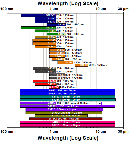
Alternatively, the selection guide graphic further below arranges our entire selection of photodiode and thermal power sensors by wavelength (left) or optical power range (right). Each box contains the item # and specified range of the sensor. These graphs allow for easy identification of the sensor heads available for a specific wavelength or power range.
| Photodiode Power Sensors |
|---|


| Thermal Power Sensors |
|---|


| Thermal Position & Power Sensors |
|---|

| Pyroelectric Energy Sensors |
|---|


Sensor Options
(Arranged by Wavelength Range)
Sensor Options
(Arranged by Power Range)
Click to Enlarge
S120C and CP44F Quick-Release Mount
- For General Purpose Optical Power Measurements
- Integrated Viewing Target for Easy Sensor Alignment
- Ø9.5 mm Sensor Aperture
- Fiber Adapters Available Separately (See Table Below)
- Sensor, Protective Cap, and IR Target Included
The S12xC Standard Photodiode Power Sensors are ideal for metering low power coherent and incoherent sources from the UV to the NIR. These sensors feature an integrated viewing target for easy alignment, enhanced shielding against electromagnetic interference, over temperature alert device, and large Ø9.5 mm sensor aperture. The sensors are compatible with Ø1/2" posts and SM1 (1.035"-40) lens tubes and are ideal for free-space and fiber-coupled sources. They may also be mounted in 30 mm cage systems using our selection of 30 mm Cage System Optic Mounts with internal SM1 threading.
Each sensor is shipped with NIST- or PTB-traceable calibration data. The included data will match the calibration certification of the photodiode used to test the individual sensor. Thorlabs offers a recalibration service for these photodiode power sensors, which can be ordered below (see Item # CAL-UVPD for UV-extended Si sensors, Item # CAL-PD for Si sensors and Item # CAL-IRPD for Ge sensors).
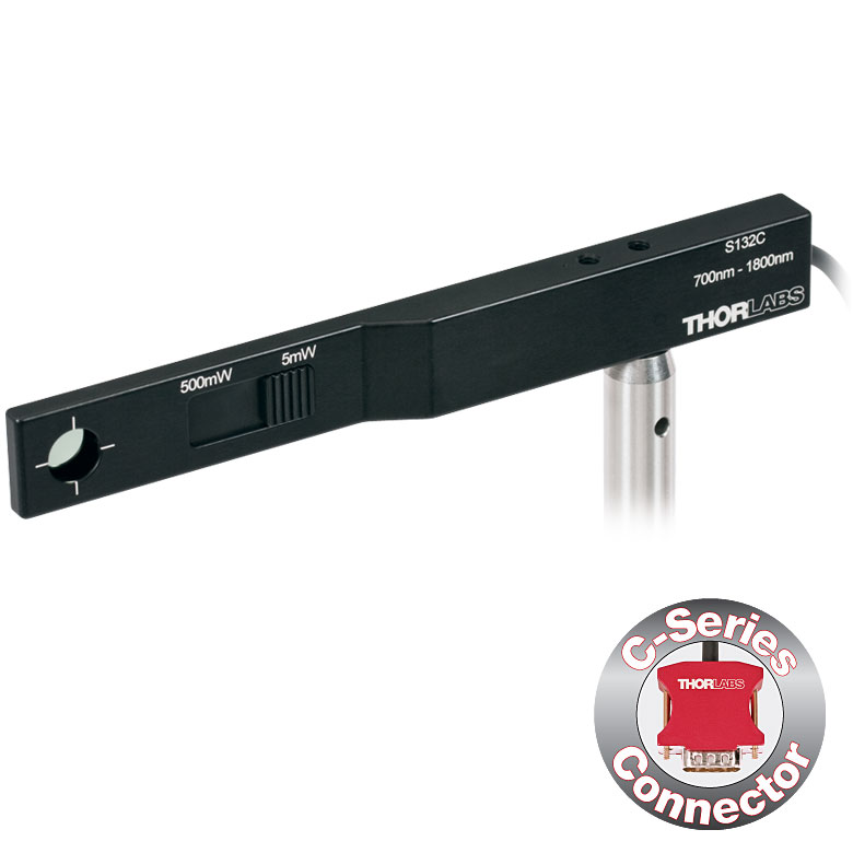
| Item #a | S120VC | S120C | S121C | S122Cb,i |
|---|---|---|---|---|
| Sensor Image (Click the Image to Enlarge) |
|
|
|
|
| Aperture Size | Ø9.5 mm | |||
| Wavelength Range | 200 - 1100 nm | 400 - 1100 nm | 400 - 1100 nm | 700 - 1800 nm |
| Power Range | 50 nW - 50 mW | 500 nW - 500 mW | 50 nW - 40 mW | |
| Detector Type | Si Photodiode (UV Extended) | Si Photodiode | Ge Photodiode | |
| Linearity | ±0.5% | |||
| Resolutionc | 1 nW | 10 nW | 2 nW | |
| Measurement Uncertaintyd | ±3% (440 - 980 nm) ±5% (280 - 439 nm) ±7% (200 - 279 nm, 981 - 1100 nm) |
±3% (440 - 980 nm) ±5% (400 - 439 nm) ±7% (981 - 1100 nm) |
±5% | |
| Responsivitye (Click for Plot) | Raw Data |
Raw Data |
Raw Data |
Raw Data |
| Coating/Diffuser | Reflective ND (OD1.5)f | Reflective ND (OD1)g | Reflective ND (OD2)h | Absorptive ND (Schott NG9) |
| Head Temperature Measurement | NTC Thermistor 4.7 kΩ | |||
| Housing Dimensions | Ø30.5 mm x 12.7 mm | |||
| Active Detector Area | 9.7 mm x 9.7 mm | |||
| Cable Length | 1.5 m | |||
| Mounting Threadf,g,h | Universal 8-32 / M4 Tap, Post Not Included | |||
| Aperture Thread | External SM1 (1.035"-40) | |||
| Fiber Adapters | S120-FC2, S120-FC, S120-APC2, S120-APC, S120-SMA, S120-ST, S120-LC, S120-SC, and S120-25 (Not Included) | |||
| Compatible Consoles | PM400, PM100D, PM100A, and PM5020 | |||
| Compatible Interfaces | PM101, PM101A, PM101R, PM101U, PM103, PM103E, PM103A, PM103U, and PM100USB | |||

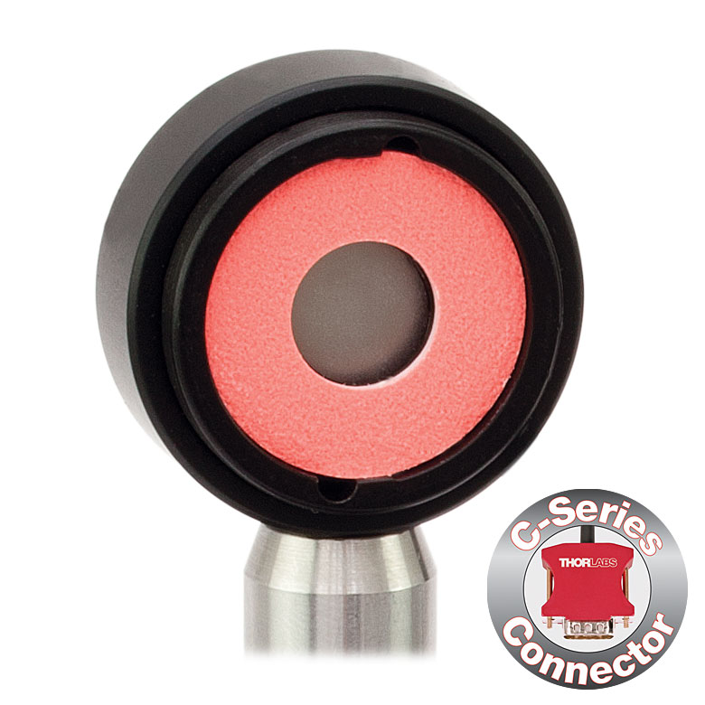


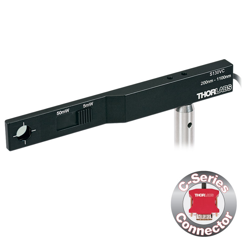
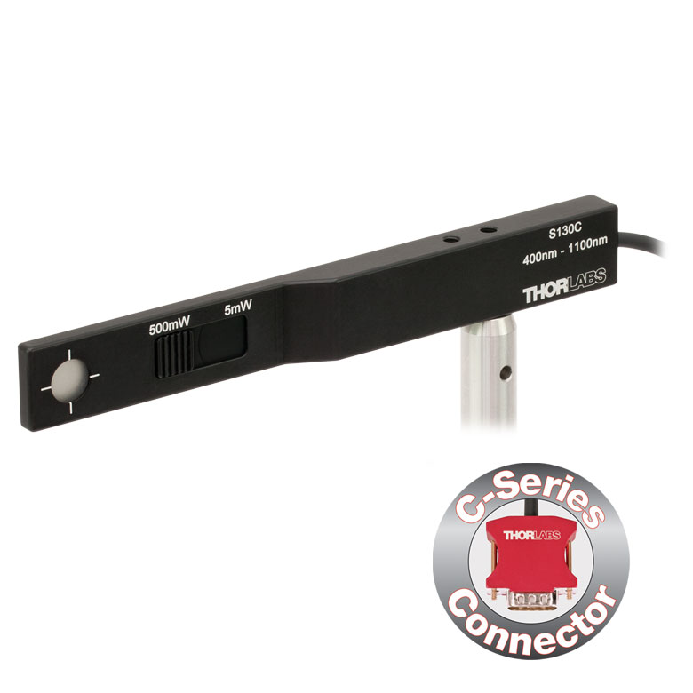
Click for Details S130C Photodiode Sensor Mounted in FiberBench System Using FBSM Mount
- For Optical Power Measurements in Confined Spaces
- Slim Design: 5 mm Thin on Sensor Side
- Ø9.5 mm Sensor Aperture
- Slideable ND Filter Automatically Changes Sensor Power Range
- Accessories Available Separately Below:
- SM1A29 Adapter with VIS/IR Target and External SM1 Threading
- FBSM Mount with VIS/IR Target for FiberBench Systems
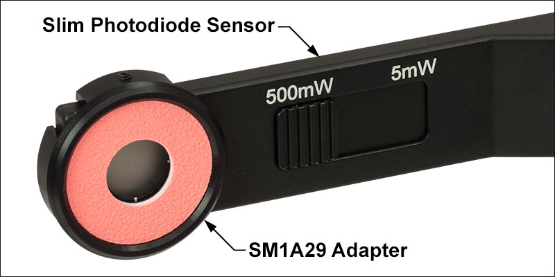
The S13xC Slim Photodiode Power Sensors are designed to take optical source power measurements in locations where space and accessibility are at a premium. The 5 mm thin
Slim Photodiode Sensors can fit between closely spaced optics, cage systems, and other arrangements where standard power meters may not fit. These sensors also feature a large Ø9.5 mm sensor aperture and slideable neutral density filter for dual power ranges in one compact device.
A separately available SM1A29 adapter can be attached by 2 setscrews to any S130 series power sensor to mount fiber adapters, light shields, filters or any other SM1-threaded (1.035"-40) mechanics or optics. The FBSM Mount allows our S130 series power sensors to be mounted vertically into FiberBench systems for stable mounting with a minimal footprint.
Each sensor is shipped with NIST- or PTB-traceable calibration data. The included data will match the calibration certification of the photodiode used to test the individual sensor. Thorlabs offers a recalibration service for these photodiode power sensors, which can be ordered below (see Item # CAL-UVPD2 for UV-extended Si sensors, Item # CAL-PD2 for Si sensors, and Item # CAL-IRPD2 for Ge sensors).
| Item #a | S130VC | S130C | S132Cb | |
|---|---|---|---|---|
| Sensor Image (Click the Image to Enlarge) |
|
|
|
|
| Aperture Size | Ø9.5 mm | |||
| Wavelength Range | 200 - 1100 nm | 400 - 1100 nm | 700 - 1800 nmc | |
| Power Range (with Filter) |
500 pW - 0.5 mWd (Up to 50 mW)d |
500 pW - 5 mW (Up to 500 mW) |
5 nW - 5 mW (Up to 500 mW) |
|
| Detector Type | Si Photodiode (UV Extended) | Si Photodiode | Ge Photodiode | |
| Linearity | ±0.5% | |||
| Resolution | 100 pWe | 1 nWf | ||
| Measurement Uncertaintyg | ±3% (440 - 980 nm) ±5% (280 - 439 nm) ±7% (200 - 279 nm, 981 - 1100 nm) |
±3% (440 - 980 nm) ±5% (400 - 439 nm) ±7% (981 - 1100 nm) |
±5% | |
| Responsivityh (Click for Plot) | Raw Data |
Raw Data |
Raw Data |
|
| Coating/Diffuser | Reflective ND (OD1.5)d | Reflective ND (OD2)i | Absorptive ND (Schott NG9/KG3)c | |
| Housing Dimensions | 150 mm x 19 mm x 10 mm; 5 mm Thickness on Sensor Side | |||
| Active Detector Area | 9.7 mm x 9.7 mm | |||
| Cable Length | 1.5 m | |||
| Mounting Thread | Separate 8-32 and M4 Taps, Posts Not Included | |||
| Adapters (Not Included) | SM1A29: Add SM1 Thread and Viewing Target to Aperture Fiber Adapters Compatible with SM1A29 Adapter: S120-FC2, S120-FC, S120-APC2, S120-APC, S120-SMA, S120-ST, S120-LC, S120-SC, and S120-25 FBSM: Integrate Sensor into FiberBench Setups |
|||
| Compatible Consoles | PM400, PM100D, PM100A, and PM5020 | |||
| Compatible Interfaces | PM101, PM101A, PM101R, PM101U, PM103, PM103A, PM103E, PM103U, and PM100USB | |||
| Item #a | S116C | |
|---|---|---|
| Sensor Image (Click the Image to Enlarge) |
|
|
| Aperture Size | Ø6 mm | |
| Wavelength Range | 400 - 1100 nm | |
| Power Range | 20 nW - 50 mW | |
| Detector Type | Si Photodiode | |
| Linearity | ±0.5% | |
| Resolution | 1 nWb | |
| Measurement Uncertaintyc | ±3% (451 - 1000 nm) ±5% (400 - 450 nm, 1001 - 1100 nm) |
|
| Responsivityd (Click for Plot) |
Raw Data |
|
| Coating/Diffuser | Absorptive ND (NG9) | |
| Housing Dimensions (L x W x T) |
70.0 mm x 11.0 mm x 8.9 mm; 10.0 mm Width and 4.5 mm Thickness on Sensor Side |
|
| Active Detector Area | 7 mm x 7 mm | |
| Cable Length | 1.5 m | |
| Mounting Threads | 2 Universal 8-32 / M4 Taps (One on the Back, One on the Bottom), Posts Not Included |
|
| Adapters (Not Included) |
SM05A29: Add SM05 Thread to Aperture Fiber Adapters Compatible with SM05A29 Adapter: PM20-FC2, PM20-FC, PM20-APC2, PM20-APC, PM20-SMA, PM20-ST, PM20-SC, and PM20-LC, and PM20-25 |
|
| Compatible Consoles | PM400, PM100D, PM100A, and PM5020 | |
| Compatible Interfaces | PM101, PM101A, PM101R, PM101U, PM103, PM103A, PM103E, PM103U, and PM100USB | |
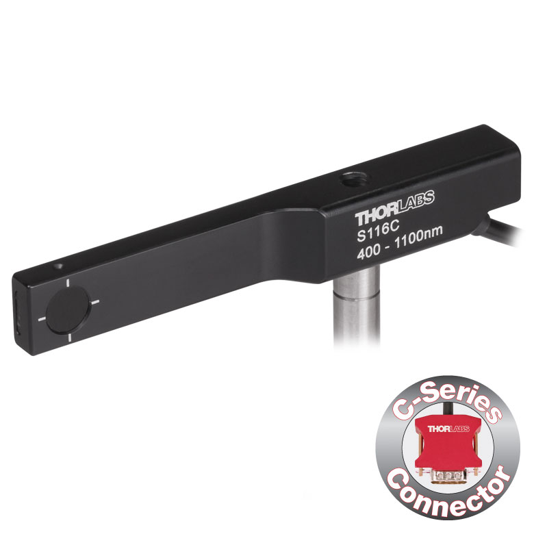
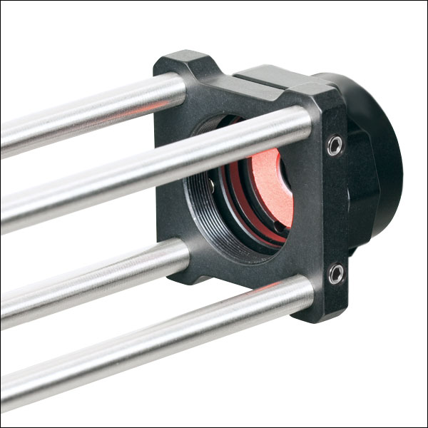
- For Optical Power Measurements in Tiny Spaces Such as 16 mm Cage Systems
- Wavelength Range: 400 - 1100 nm
- Very Slim Design: 10.0 mm Wide and 4.5 mm Thin on Sensor Side
- Silicon Photodiode with Ø6 mm Sensor Aperture
- Designed for Power Measurements for Low Power Lasers
- Post Mountable via 8-32 (M4) Taps
- SM05A29 Adapter with External SM05 (0.535"-40) Threading Available Separately Below
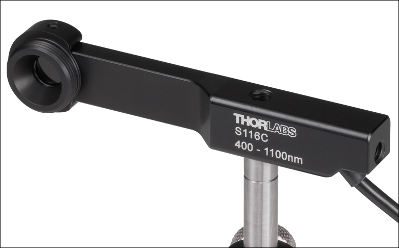
The S116C Compact Slim Photodiode Power Sensor is designed to take optical source power measurements in locations where space and accessibility are at a premium. The 4.5 mm thin photodiode sensor can fit between the rods of a 16 mm cage system, as seen in the application photo below, as well as through the side openings of our slotted Ø1/2" lens tubes (Item #s SM05L20C and SM05L30C). This sensor also features a Ø6 mm sensor aperture.
A separately available SM05A29 adapter can be attached by two 0.05" (1.3 mm) hex setscrews to an S116C power sensor to mount fiber adapters, light shields, filters or any other SM05-threaded (0.535"-40) mechanics or optics. The adapter mounted on the S116C power sensor is shown below.
Each sensor is shipped with NIST- and PTB-traceable calibration data. The included data is determined with the help of a certified reference diode, which corresponds to the spectral range of the sensor to be calibrated. Thorlabs offers a recalibration service for these photodiode power sensors, which can be ordered below (see Item # CAL-PD for Si sensors).
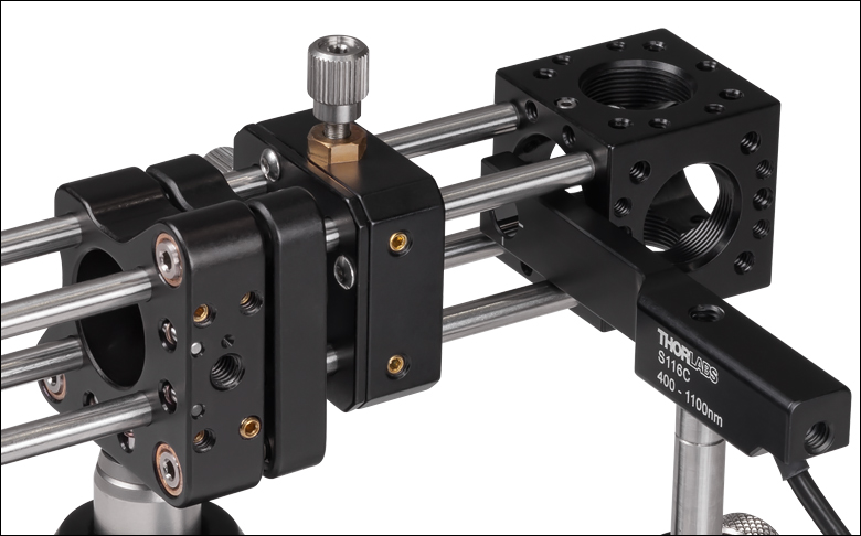
Click to Enlarge S116C Sensor in a 16 mm Cage System
Click for Details
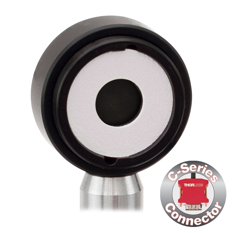
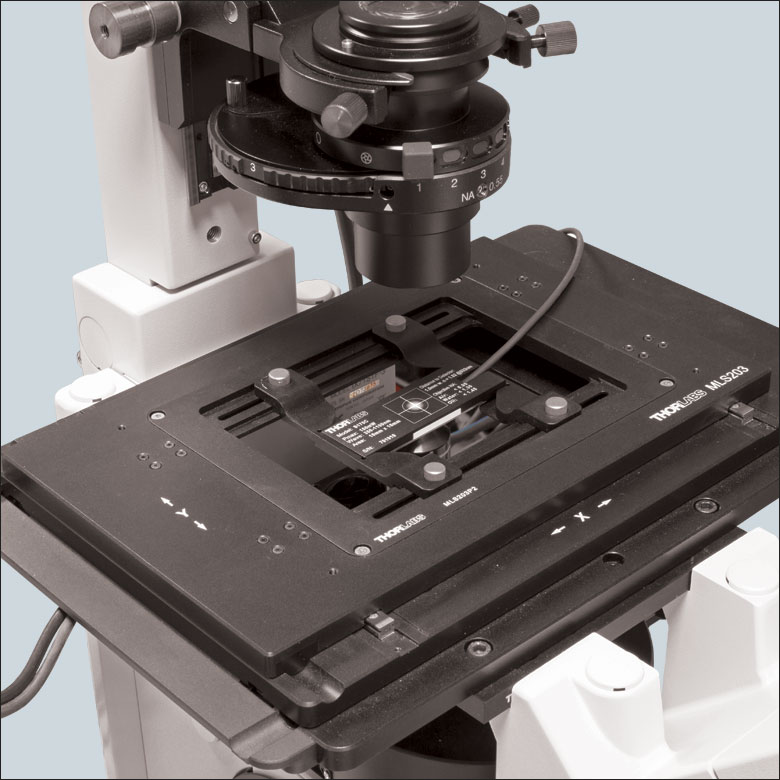
Using the engraved alignment target on the back of the sensor housing, a user can position the stage so that when the sensor is flipped, the beam strikes the center of the sensor. The S170C sensor is shown in this image.
- Designed to Measure Optical Power at the Sample Plane of a Microscope
- Silicon Photodiode with Large 18 mm x 18 mm Active Area
- Sensor Housing Dimensions: 76.0 mm x 25.2 x 5.0 mm
- Novel Optical Design Accommodates High NA Objectives
- Information Stored in Connector
- Sensor Data
- NIST- and PTB-Traceable Calibration Data
- Post Mountable via 8-32 (M4 x 0.7) Tap
The Microscope Slide Power Sensor Heads with silicon photodiodes are designed to measure the power at the sample plane in microscopy setups. The S170C sensor can detect wavelengths from 350 nm to 1100 nm at optical powers from 10 nW to 150 mW, while the S171C sensor can detect wavelengths from 400 nm to 1100 nm at powers from 1 nW to 15 mW. The NS170C sensor is designed to measure the relative peak power of femtosecond lasers with center wavelengths from 780 nm to 1300 nm and average powers from 0.5 mW to 350 mW. Each sensor head's 76.0 mm x 25.2 mm footprint matches that of a standard microscope slide and is compatible with most standard upright and inverted microscopes.
The photodiodes used in the S170C and S171C sensors have 18 mm x 18 mm active areas and are contained in sealed housings behind neutral density (ND) filters. A 20 mm x 20 mm indentation around the surface of the ND filter is sized to accept standard microscope cover slips. An immersion medium (water, glycerol, oil) may be placed in this well directly over the ND filter, or a cover slip may be inserted first to simplify clean up. The gap between the photodiode and the neutral density filter has been filled with an index matching gel in order to prevent internal reflections from causing significant measurement errors when using high NA objectives with oil or water.
The NS170C sensor is designed to measure the relative peak power of two-photon lasers by utilizing a second-order nonlinear β-BBO crystal to convert incident ultrafast NIR pulses into their visible second harmonic. Shortpass filters underneath the β-BBO crystal reject the residual NIR light, allowing only the second harmonic light to transmit down to a large area silicon photodiode sensor. At the entrance of the sensor is a 170 µm thick cover glass sealed to the sensor housing, allowing the sensor to be used with dry, water immersion, and oil immersion objectives. The working distance from the top of the cover glass to the β-BBO crystal is 0.22 mm.
The bottom of each sensor housing features a laser-engraved grid to aid in aligning and focusing the beam. In standard microscopes, this grid can be used for beam alignment before flipping the sensor head to face the objective for power measurements. In inverted microscopes, turn on the transmitted illuminator to align the grid on the detector housing with the beam, thereby centering the sensor in front of the objective. Alternatively, the diffusive surface of the ND filter can be used as a focusing plane.
To avoid damaging the sensor, we recommend positioning it in the light path at a location where the beam is not focused. It is important not to exceed the Max Average Power Density over the beam's spot size for the S170C and S171C sensors, and the Max Peak Power Density for the NS170C sensor (see Specs tab) .
Each sensor is shipped with NIST- or PTB-traceable calibration data. The included data will match the calibration certification of the photodiode used to test the individual sensor. Sensor specifications and the included NIST- or PTB-traceable calibration data are stored in non-volatile memory in the sensor connector and can be read out by the latest generation of Thorlabs power meters. Please note that the NS170C sensor's NIST and PTB calibration is for the visible light incident on the detector; however, the magnitude of that visible light is specific to the illumination conditions of the NIR femtosecond pulses. We recommend yearly recalibration to ensure accuracy and performance, which can be ordered below (see Item # CAL-PD for S170C and S171C sensors, and Item # CAL-NS for the NS170C sensor). Please contact Tech Support for more information.
The complete set of specifications are presented on the Specs tab above. Thorlabs also offers a Microscope Slide Sensor Head with a thermal sensor; the full presentation can be found here.
| Item #a | S170C | S171C | NS170C |
|---|---|---|---|
| Sensor Image (Click Image to Enlarge) |
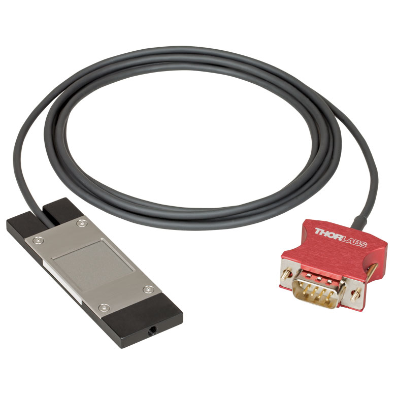 |
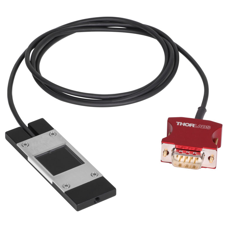 |
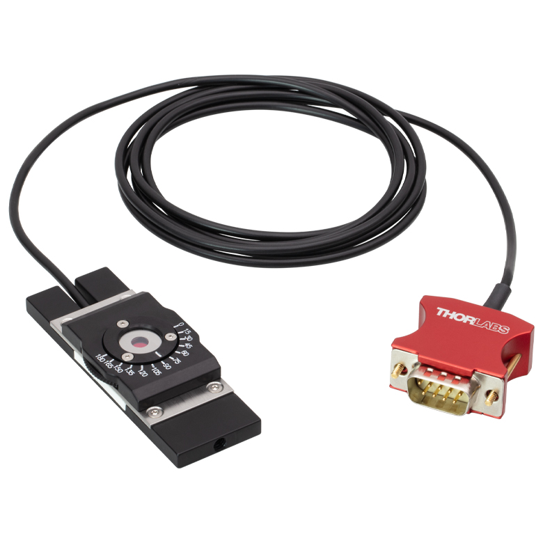 |
| Dimensions | 76.0 mm x 25.2 mm x 5.0 mm (2.99" x 0.99" x 0.20") |
Base: 76.0 mm x 25.2 mm x 5.0 mm (2.99" x 0.99" x 0.20") Overall: 76.0 mm x 30.0 mm x 11.0 mm (2.99" x 1.18" x 0.43") |
|
| Active Detector Area | 18 mm x 18 mm | ||
| Input Aperture | 20 mm x 20 mm | Ø4.5 mm | |
| Wavelength Range | 350 - 1100 nm | 400 - 1100 nm | Laser: 780 - 1300 nm SHG: 390 - 650 nm |
| Optical Power Working Range | 10 nW - 150 mW | 1 nW - 15 mW | Laser: 0.5 - 350 mWb SHG: 10 nW - 5 mW |
| Max Peak Power Densityc | - | - | 10 TW/cm2 |
| Detector Type | Silicon Photodiode | Second-Order Nonlinear Crystal with Silicon Photodiode |
|
| Linearity | ±0.5% | ±0.5%d | |
| Resolution | 1 nWe | 0.5 pWf | 1 nWd,e |
| Measurement Uncertaintyg | ±3% (440 - 980 nm) ±5% (350 - 439 nm) ±7% (981 - 1100 nm) |
±3% (440 - 980 nm)h ±5% (400 - 439 nm)h ±7% (981 - 1100 nm)h |
±3% (440 - 650 nm)d ±5% (390 - 439 nm)d |
| Responsivityi (Click for Plot) |
Raw Data |
Raw Data |
Raw Data |
| Neutral Density Filter | Reflective (OD 1.5) | Absorptive (OD 0.4) | N/A |
| Cable Length | 1.5 m | ||
| Mounting Thread | Universal 8-32 / M4 x 0.7 Tap, Post Not Included | ||
| Compatible Consoles | PM400, PM100D, PM100A, and PM5020 | ||
| Compatible Interfaces | PM101, PM101A, PM101R, PM101U, PM103, PM103A, PM103E, PM103U, and PM100USB | ||
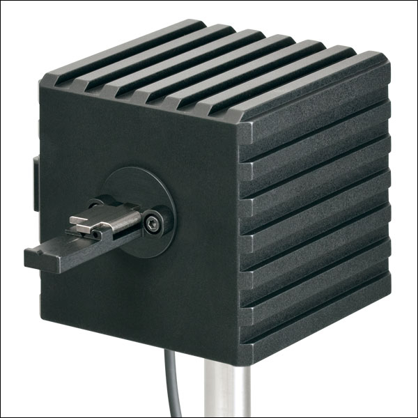
Click to Enlarge
S142C and S140-BFA Bare Fiber Adapter (Sold Separately)
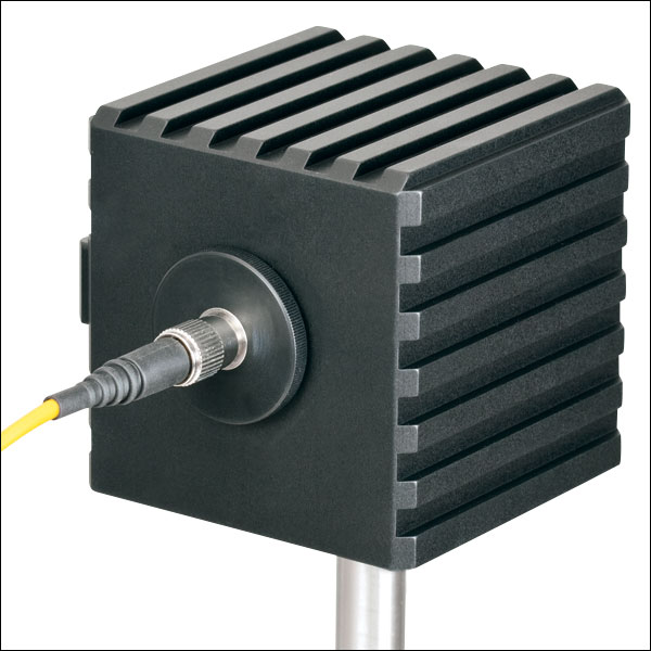
Click to Enlarge
S142C with the S120-FC Fiber Adapter (Included)
- For Measurements Independent of Beam Shape and Entrance Angle
- Integrating Sphere Design Acts as a Diffuser with Minimal Power Loss
- Ø5 mm, Ø7 mm, Ø12 mm, or Ø22 mm Input Sensor Aperture
- Spheres with Apertures ≤Ø12 mm Include a Removable S120-FC Fiber Adapter (FC/PC and FC/APC)
- Fiber Adapters for Terminated and Bare Fiber (See Table Below) are Compatible with Spheres with Apertures ≤Ø12 mm
These Integrating Sphere Photodiode Power Sensors are the ideal choice for power measurements independent of beam uniformity, divergence angle, beam shape, or entrance angle, making them excellent for use with fiber sources and off-axis free space sources. They feature enhanced shielding to avoid electromagnetic interference and an over-temperature alert sensor to warn against damage and measurement errors due to overheating of the sensor.
Our integrating spheres are designed for wavelength ranges from the visible through the NIR. Sensor heads for use between 350 and 2500 nm use a single Ø1" or Ø2" sphere made from Zenith® PTFE and feature a black housing to minimize reflected light around the entrance aperture. These sensors use either a silicon photodiode for detection in the 350 - 1100 nm range or an InGaAs photodiode for detection in the 800 - 1700 nm, 900 - 1650 nm, or 1200 - 2500 nm wavelength range.
The S180C integrating sphere for 2.9 - 5.5 µm uses two connected, gold-plated Ø20 mm spheres, with an entrance port in the first sphere and a port for the MCT (HgCdTe) detector located in the second sphere. Compared to single-sphere designs, the two-sphere configuration improves device sensitivity by minimizing the internal sphere surface area while still effectively shielding the detector from direct illumination. This design reduces the effect of input angle, divergence, and beam shape on the measurement result by effectively shielding the photodiode without the use of a baffle or other shielding mechanism.
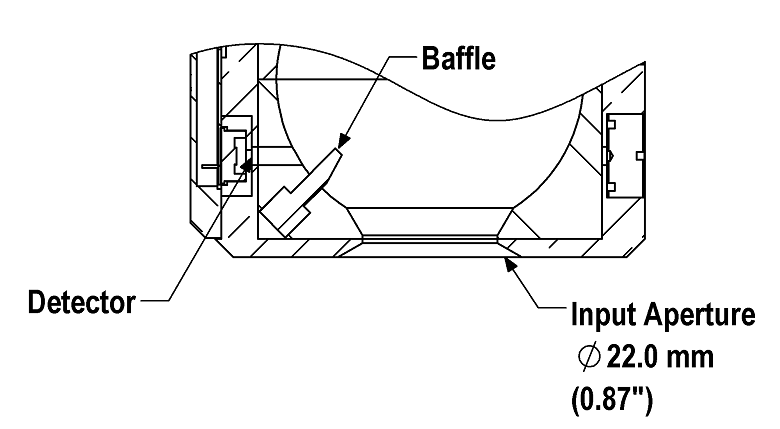
Click to Enlarge
A baffle on the S142CL and S145CL spheres blocks light from directly hitting the detector.
The integrating spheres with Ø5 mm, Ø7 mm, or Ø12 mm apertures feature large active detector areas, and externally SM1-threaded (1.035"-40) adapters for compatibility with the included S120-FC fiber adapter. Because of the large active detector areas of these sensors, the included S120-FC fiber adapter can be used with FC/PC- or FC/APC-terminated fiber. The externally SM1-threaded adapter can be removed using a size 1 screwdriver to place components closer to the window.
The S142CL and S145CL integrating spheres feature a large Ø22 mm input aperture and a baffle within the sphere which prevents direct illumination of the photodiode. The large aperture and baffle enable measurements of large and divergent beams, such as those emitted from LED and VCSEL light sources. The input face of the detectors have four 4-40 threads for mounting 30 mm cage system components. Additionally, insertion of a second or third port in the sensor head is possible on request, please contact Tech Support for details.
Each sensor is shipped with NIST- or PTB-traceable calibration data. The included data will match the calibration certification of the photodiode used to test the individual sensor. NIST- or PTB-traceable data is stored in the sensor connector. Thorlabs offers a recalibration service for these photodiode power sensors, which can be ordered below (see Item # CAL-PD for Si sensors, Item # CAL-IRPD for InGaAs sensors, and Item # CAL-MIRPD for extended InGaAs or MCT sensors).
| Item #a | S140C | S142C | S142CL | S144C | S145C | S145CL | S146C | S148C | S180C | |
|---|---|---|---|---|---|---|---|---|---|---|
| Sensor Image (Click the Image to Enlarge) |
 |
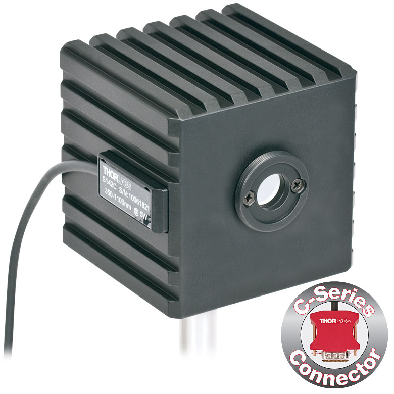 |
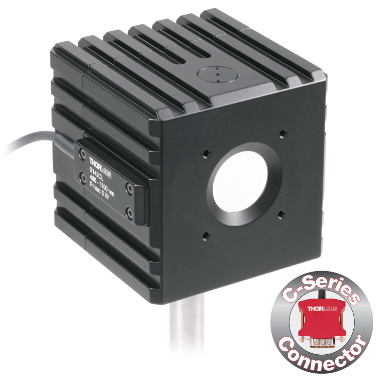 |
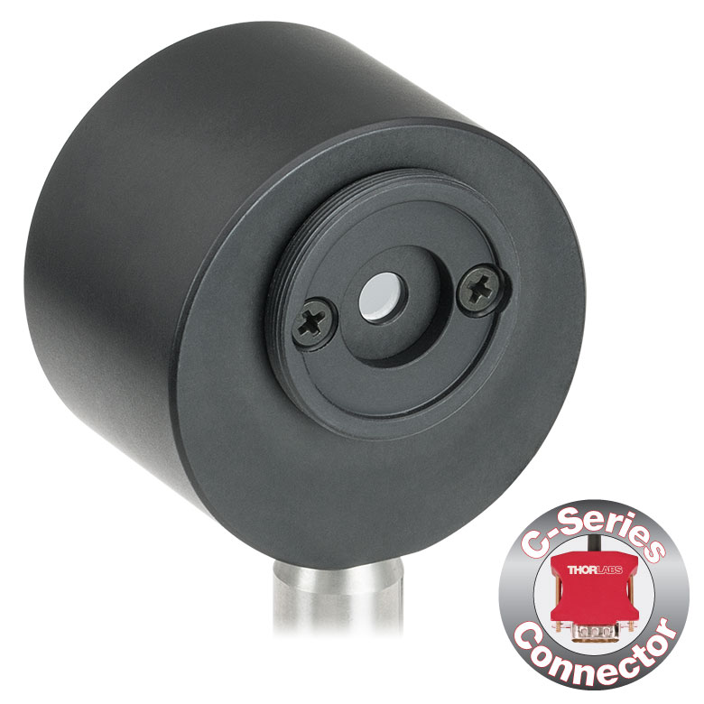 |
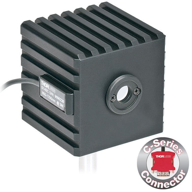 |
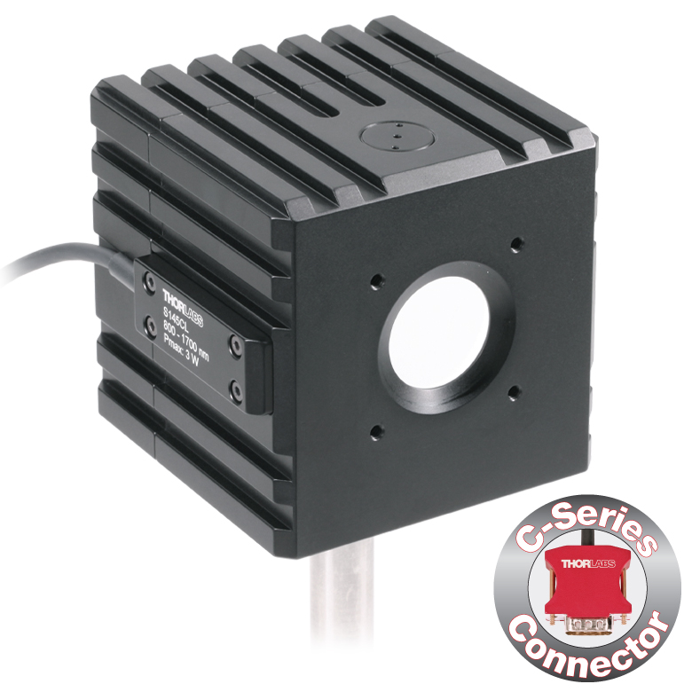 |
 |
|
 |
|
| Aperture Size | Ø5 mm | Ø12 mm | Ø22 mm | Ø5 mm | Ø12 mm | Ø22 mm | Ø12 mm | Ø5 mm | Ø7 mm | |
| Wavelength Range | 350 - 1100 nm | 400 - 1100 nm | 800 - 1700 nm | 900 - 1650 nm | 1200 - 2500 nm | 2.9 µm - 5.5 µm | ||||
| Power Range | 1 µW - 500 mW | 1 µW - 5 W | 10 µW - 5 W | 1 µW - 500 mW | 1 µW - 3 W | 10 µW - 3 W | 10 µW - 20 W | 1 µW - 1 W | 1 µW - 3 W | |
| Detector Type | Si Photodiode | Si Photodiode with Baffle | InGaAs Photodiode | InGaAs Photodiode with Baffle | InGaAs Photodiode | Extended InGaAs Photodiode | MCT (HgCdTe) Photodiode |
|||
| Linearity | ±0.5% | |||||||||
| Resolutionb | 1 nW | 10 nW | 1 nW | 10 nW | 1 nW | 10 nW | ||||
| Measurement Uncertaintyc,d |
±3% (440 - 980 nm) ±5% (350 - 439 nm) ±7% (981 - 1100 nm) |
±3% (440 - 980 nm) ±5% (400 - 439 nm) ±7% (981 - 1100 nm) |
±5% | |||||||
| Responsivitye (Click for Plot) |
Raw Data |
Raw Data |
Raw Data |
Raw Data |
Raw Data |
Raw Data |
Raw Data |
Raw Data |
Raw Data |
|
| Integrating Sphere Material (Size) |
Zenith® PTFE (Ø1") |
Zenith® PTFE (Ø2") |
Zenith® PTFE (Ø1") |
Zenith® PTFE (Ø2") |
Zenith® PTFE (Ø1") |
Gold Plating (Two Ø20 mm Spheres) |
||||
| Head Temperature Measurement |
NTC Thermistor 4.7 kΩ | |||||||||
| Housing Dimensions |
Ø45 mm x 30.5 mm | 70 mm x 74 mm x 70 mm | Ø45 mm x 30.5 mm | 70 mm x 74 mm x 70 mm | Ø45 mm x 30.5 mm | 59.0 mm x 50.0 mm x 28.5 |
||||
| Active Detector Area | 3.6 mm x 3.6 mm | Ø2 mm | Ø3 mm | Ø1 mm | Ø1 mm | 1 mm x 1 mm | ||||
| Cable Length | 1.5 m | |||||||||
| Mounting Thread | Separate 8-32 and M4 Taps, Posts Not Included | Universal 8-32 / M4 Thread, Post Not Included | Separate 8-32 and M4 Taps, Posts Not Included | Universal 8-32 / M4 Thread, Post Not Included | Separate 8-32 and M4 Taps, Posts Not Included | Universal |
||||
| Aperture Thread | Included Adapter with SM1 (1.035"-40) External Thread | None | Included Adapter with SM1 (1.035"-40) External Thread | None | Included Adapter with SM1 (1.035"-40) External Thread | |||||
| Compatible Fiber Adapters |
S120-FC (Included) S120-FC2, S120-APC2, S120-APC, S120-SMA, S120-ST, S120-SC, S120-LC, S120-25, and S140-BFA (Not Included) |
None | S120-FC (Included) S120-FC2, S120-APC2, S120-APC, S120-SMA, S120-ST, S120-SC, S120-LC, S120-25, and S140-BFA (Not Included) |
None | S120-FC (Included) S120-FC2, S120-APC2, S120-APC, S120-SMA, S120-ST, S120-SC, S120-LC, S120-25, and S140-BFA (Not Included) |
|||||
| Compatible Consoles | PM400, PM100D, PM100A, and PM5020 | |||||||||
| Compatible Interfaces | PM101, PM101A, PM101R, PM101U, PM103, PM103A, PM103E, PM103U, and PM100USB | |||||||||

 Zoom
Zoom
- Compatible with S140C Series Power Sensors
- Power Measurements of Bare Fiber Outputs
- Easy Loading and Positioning of Optical Fiber in V-Groove
- Supports Fiber with Buffer Diameters from 250 to 450 µm
- Tight Holding without Fiber Damage by Magnetic Clip
- Attached by Two M2.5 x 4 mm Cap Screws
Click to Enlarge
PM100D with S150C Sensor and FC Cable
- For Fiber-Based Optical Power Measurements
- Compact Sensor Integrated into the Connector
- Integrated Design for use in the Field and Lab
- Includes FC/PC Adapter
- S150C and S151C Sensors also Include SMA Adapter
- Compatible FC/APC, LC/PC, SC/PC, and ST®* Fiber Adapters Also Available (See Table Below)
- Compatible with the PM100D, PM100USB, and PM100A Consoles
The S15xC Compact Fiber Photodiode Power Sensor is designed to take power measurements from a wide variety of fiber-coupled sources. The compact sensor, integrated into the power meter connector, features a unique integrated design housing the photodiode sensor, fiber coupling, and NIST- or PTB-traceable data. The fiber adapter included with each sensor can be interchanged easily to accomodate a variety of fiber connectors (see table below).
Each sensor is shipped with NIST- or PTB-traceable calibration data. The included data will match the calibration certification of the photodiode used to test the individual sensor. NIST- or PTB-traceable data is stored in the sensor connector. Thorlabs offers a recalibration service for these photodiode power sensors, which can be ordered below (see Item # CAL-PD for Si sensors and Item # CAL-IRPD for InGaAs sensors).
*ST® is a registered trademark of Lucent Technologies, Inc.
| Item #a | S150C | S151C | S154C | S155C |
|---|---|---|---|---|
| Sensor Image (Click the Image to Enlarge) |
|
|
|
|
| Wavelength Range | 350 - 1100 nm | 400 - 1100 nm | 800 - 1700 nm | |
| Power Range | 100 pW to 5 mW (-70 dBm to +7 dBm) |
1 nW to 20 mW (-60 dBm to +13 dBm) |
100 pW to 3 mW (-70 dBm to +5 dBm) |
1 nW to 20 mW (-60 dBm to +13 dBm) |
| Detector Type | Si Photodiode | InGaAs Photodiode | ||
| Linearity | ±0.5% | |||
| Resolutionb | 10 pW (-80 dBm) | 100 pW (-70 dBm) | 10 pW (-80 dBm) | 100 pW (-70 dBm) |
| Measurement Uncertaintyc | ±3% (440 - 980 nm) ±5% (350 - 439 nm) ±7% (981 - 1100 nm) |
±3% (440 - 980 nm) ±5% (400 - 439 nm) ±7% (981 - 1100 nm) |
±5% | |
| Responsivityd (Click for Details) | Raw Data |
Raw Data |
Raw Data |
Raw Data |
| Coating/Diffuser | N/A | Absorptive ND (Schott NG3) | N/A | |
| Head Temperature Measuremente | NTC Thermistor 3 kΩ | |||
| Aperture Thread | External SM05 (0.535"-40) | |||
| Fiber Adaptersf | Included (FC and SMA): PM20-FC and PM20-SMA; Optional: PM20-FC2, PM20-APC2, PM20-APC, PM20-ST, PM20-SC,PM20-LC, and PM20-25 |
Included (FC): PM20-FC; Optional: PM20-FC2, PM20-APC2, PM20-APC, PM20-SMA, PM20-ST, PM20-SC, PM20-LC, and PM20-25 |
||
| Compatible Consoles | PM400, PM100D, PM100A, and PM5020 | |||
| Compatible Interfaces | PM101, PM101A, PM101R, PM101U, PM103, PM103A, PM103E, PM103U, and PM100USB | |||


These internally SM05-threaded (0.535"-40) adapters mate terminated fiber to our free-space detectors and power sensors, including, but not limited to:
- S15xC Fiber Power Meter Sensors (Sold Above)
- PM160 Wireless, Handheld Power Meter
- PM20 Series Fiber Power Meters
For details on narrow versus wide key connectors, please see our Intro to Fiber tutorial. Please contact Tech Support if you are unsure if the adapter is mechanically compatible.
The PM20-25 ferrule adapter is designed without a locking connector mechanism and accepts fiber patch cables with Ø2.5 mm ferrules for quick power meter measurements.
| Item # | PM20-FC2 | PM20-FC | PM20-APC2a | PM20-APCa | PM20-SMA | PM20-ST | PM20-SC | PM20-LC | PM20-25 |
|---|---|---|---|---|---|---|---|---|---|
| Adapter Image (Click the Image to Enlarge) |
 |
 |
 |
 |
 |
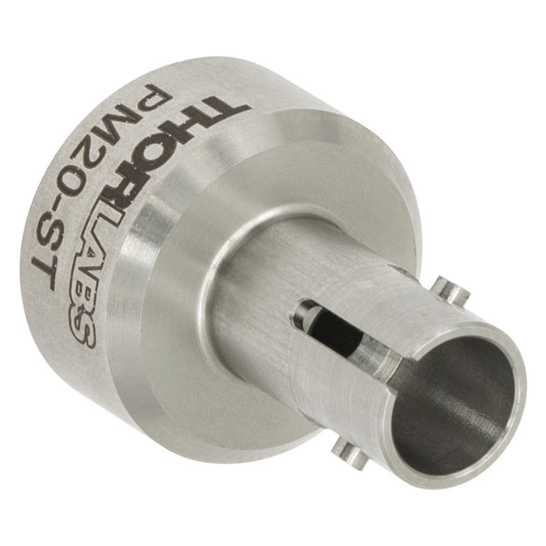 |
 |
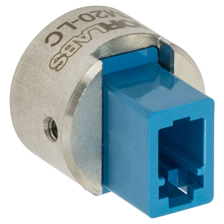 |
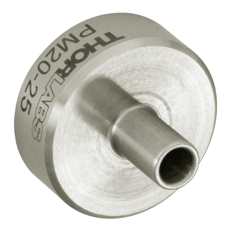 |
| Connector Type | FC/PC, 2.0 mm Narrow Key |
FC/PC, 2.2 mm Wide Key |
FC/APC, 2.0 mm Narrow Key |
FC/APC, 2.2 mm Wide Key |
SMA | ST®b/PC | SC/PCc | LC/PC | Ø2.5 mm Ferrule |
| Threading | Internal SM05 (0.535"-40) | ||||||||
These internally SM1-threaded (1.035"-40) adapters mate terminated fiber to any of our externally SM1-threaded components, including a selection of our photodiode power sensors, our thermal power sensors, and our photodetectors.
For details on narrow versus wide key connectors, please see our Intro to Fiber tutorial. Please contact Tech Support if you are unsure if the adapter is mechanically compatible.
The APC adapters have two dimples in the front surface that allow them to be tightened with the SPW909 or SPW801 spanner wrench. The dimples do not go all the way through the disk so that the adapter can be used in light-tight applications when paired with SM1 lens tubes.
The S120-25 ferrule adapter is designed without a locking connector mechanism and accepts fiber patch cables with Ø2.5 mm ferrules for quick measurements with photodetectors or power sensors.
| Item # | S120-FC2 | S120-FC | S120-APC2a | S120-APCa | S120-SMA | S120-ST | S120-SC | S120-LC | S120-25 |
|---|---|---|---|---|---|---|---|---|---|
| Adapter Image (Click the Image to Enlarge) |
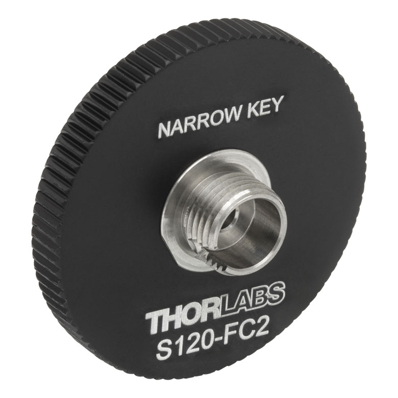 |
 |
 |
 |
 |
 |
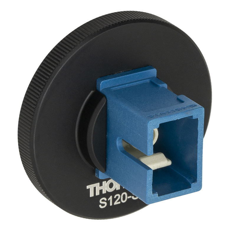 |
 |
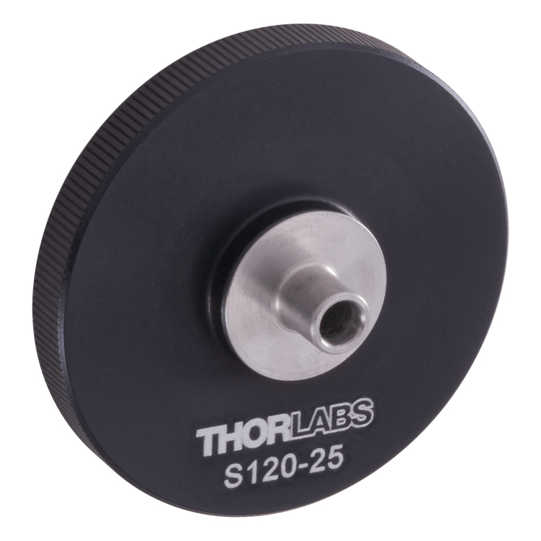 |
| Fiber Connector Type | FC/PC, 2.0 mm Narrow Key |
FC/PC, 2.2 mm Wide Key |
FC/APC, 2.0 mm Narrow Key |
FC/APC 2.2 mm Wide Key |
SMA | ST®b/PC | SC/PCc | LC/PC | Ø2.5 mm Ferrule |
| Threading | Internal SM1 (1.035"-40) | ||||||||

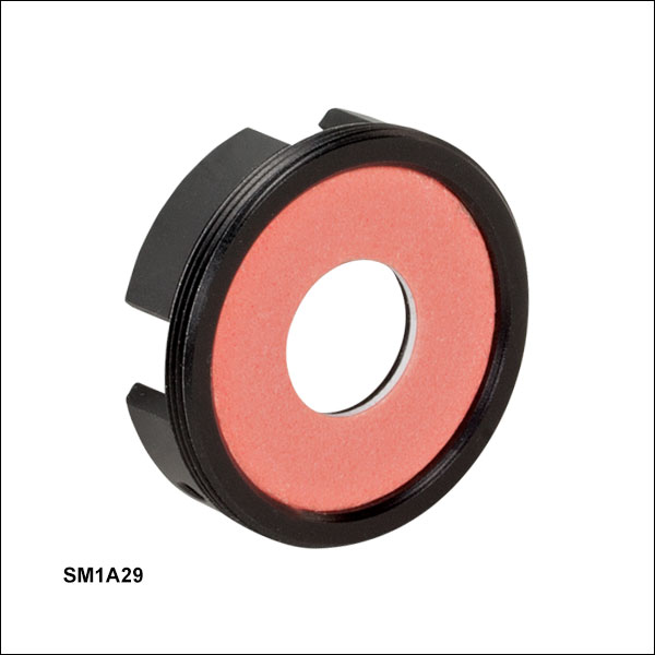 Zoom
Zoom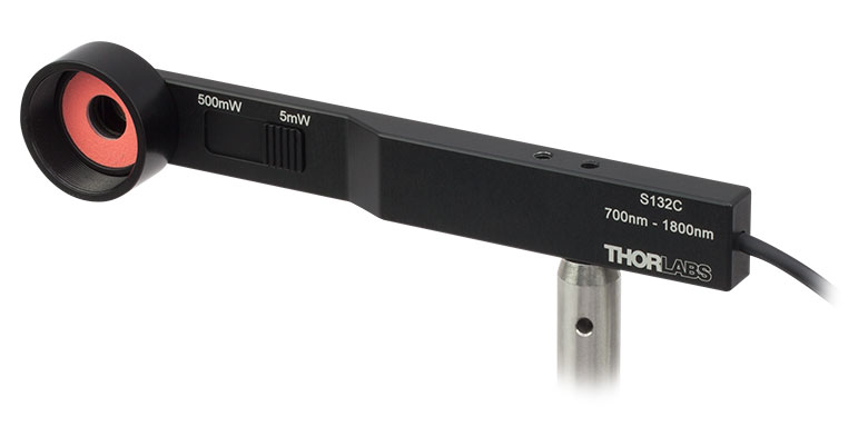
Click to Enlarge
SM1 Lens Tube Mounted on an S132C Photodiode Sensor Using an SM1A29 Adapter
- Compatible with Thorlabs Slim Photodiode Power Sensors
- Enables Integration with SM1-Threaded Components
- Adds VIS/IR Target Around Sensor
The SM1A29 adapter can be attached to our slim photodiode sensors using two setscrews, which are compatible with 0.035" (0.9 mm) hex keys. This allows for mounting SM1-threaded fiber adapters, filters, or other SM1-threaded mechanics or optics to our slim photodiode sensors. The target around the aperture uses the same material as our VRC2 Laser Viewing Card and is sensitive to light between the wavelength ranges of 400 - 645 nm and 800 - 1700 nm.

 Zoom
ZoomClick for Details S130C Photodiode Sensor Mounted in FiberBench System Using FBSM Adapter
- Compatible with Thorlabs Slim Photodiode Power Sensors
- Enables Integration with Single- and Multi-Axis FiberBench Systems
- Adds VIS/IR Target Around Sensor
The FBSM FiberBench Mount enables stable mounting of our slim photodiode sensors into our FiberBench systems. A side-located setscrew with a 0.050" (1.3 mm) hex can be used to lock the sensor in place. The mount has dowel pins for compatibility with FiberBenches and an optical axis height of 0.56" (14.2 mm) to match other FiberBench components. The target around the aperture uses the same material as our VRC2 Laser Viewing Card and is sensitive to light between the wavelength ranges of 400 - 645 nm and 800 - 1700 nm.

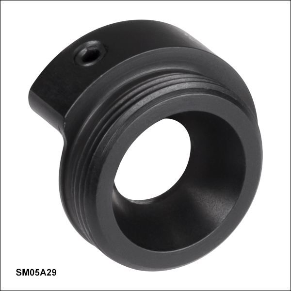 Zoom
Zoom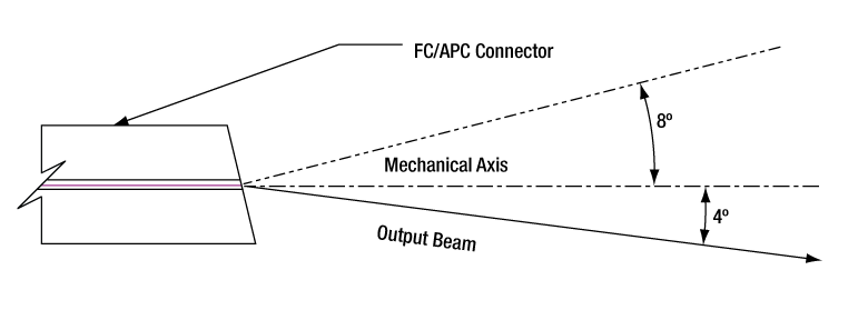
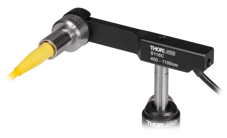
Click to Enlarge
P1-630A-FC-1 Fiber with PM20-FC Fiber Adapter Mounted on an S116C Photodiode Sensor Using an SM05A29 Adapter
- Compatible with Thorlabs' Compact Slim Photodiode Power Sensor
- Enables Integration with SM05-Threaded Components
The SM05A29 adapter can be attached to our compact slim photodiode sensors using two setscrews, which are compatible with 0.05" (1.3 mm) hex keys. This allows for mounting SM05-threaded fiber adapters, filters, or other SM05-threaded mechanics or optics to our compact slim photodiode sensors.
| Calibration Service Item # | Compatible Sensors |
|---|---|
| CAL-UVPD | S120VC |
| CAL-PD | S116C, S120C, S121C, S170C, S171C, S140C, S142C, S142CL, S150C, S151C, PM16-120, PM16 |
| CAL-UVPD2 | S130VC |
| CAL-PD2 | S130C, PM16-130, PM160 |
| CAL-NS | NS170C |
| CAL-IRPD | S122C, S144C, S145C, S145CL, S146C, S154C, S155C, PM16-122, PM16-144 |
| CAL-IRPD2 | S132C |
| CAL-MIRPD | S148C, S180C |
Thorlabs offers recalibration services for our photodiode optical power sensors. To ensure accurate measurements, we recommend recalibrating the sensors annually. Recalibration of a single-channel power and/or energy meter console or interface is included with the recalibration of a sensor at no additional cost. If you wish to calibrate one or more sensors with a dual-channel console, each sensor and console calibration service will need to be purchased individually. For more details on these recalibration services, please click the Documents (![]() ) icons below.
) icons below.
Refer to the table to the right for the appropriate calibration service Item # that corresponds to your power sensor.
Requesting a Calibration
Thorlabs provides two options for requesting a calibration:
- Complete the Returns Material Authorization (RMA) form. When completing the RMA form, please enter your name, contact information, the Part #, and the Serial # of each item being returned for calibration; in the Reason for Return field, select "I would like an item to be calibrated." All other fields are optional. Once the form has been submitted, a member of our RMA team will reach out to provide an RMA Number, return instructions, and to verify billing and payment information.
- Select the appropriate sensor calibration Item # below, enter the Part # and Serial # of the sensor that requires recalibration, and then Add to Cart. If you would like a console calibrated with your sensor, repeat this process for Item # CAL-PM1 or CAL-PM2 below, entering the console Item # and Serial #. A member of our RMA team will reach out to coordinate the return of the item(s) for calibration. Note that each console calibration Item # represents the cost of calibrating a console alone; if requesting a single-channel console calibration with a sensor calibration, the appropriate discount will be applied when your request is processed. Should you have other items in your cart, note that the calibration request will be split off from your order for RMA processing.
Please Note: To ensure your item being returned for calibration is routed appropriately once it arrives at our facility, please do not ship it prior to being provided an RMA Number and return instructions by a member of our team.
| Calibration Service Item # | Compatible Consoles & Interfaces |
|---|---|
| Single-Channel | |
| CAL-PM1 | PM100D, PM100A, PM400, PM100USB, PM101 Series, PM102 Series, PM103 Series |
| Dual-Channel | |
| CAL-PM2 | PM5020, Previous-Generation PM320E |
These recalibration services are for the power and/or energy meter electronics of our consoles and interfaces. To ensure accurate measurements, we recommend recalibrating annually. Recalibration of a single-channel console or interface is included with these sensor recalibration services at no additional cost. If you wish to calibrate one or more sensors with a dual-channel console, each sensor and console calibration service will need to be purchased individually. For more details on these recalibration services, please click the Documents (![]() ) icons below.
) icons below.
The table to the upper right lists the power and/or energy meter consoles and interfaces that can be calibrated using the CAL-PM1 and CAL-PM2 recalibration services.
Requesting a Calibration
Thorlabs provides two options for requesting a calibration:
- Complete the Returns Material Authorization (RMA) form. When completing the RMA form, please enter your name, contact information, the Part #, and the Serial # of each item being returned for calibration; in the Reason for Return field, select "I would like an item to be calibrated." All other fields are optional. Once the form has been submitted, a member of our RMA team will reach out to provide an RMA Number, return instructions, and to verify billing and payment information.
- Select the appropriate Item # below, enter the Part # and Serial # of the item that requires recalibration, and then Add to Cart. If you would like to calibrate one or more sensors with your console, repeat this process for the appropriate sensor recalibration service above, entering the console Item # and Serial #. A member of our RMA team will reach out to coordinate return of the item(s) for calibration. Note that each console calibration Item # represents the cost of calibrating a console alone; if requesting a single-channel console calibration with a sensor calibration, the appropriate discount will be applied when your request is processed. Should you have other items in your cart, note that the calibration request will be split off from your order for RMA processing.
Please Note: To ensure your item being returned for calibration is routed appropriately once it arrives at our facility, please do not ship it prior to being provided an RMA Number and return instructions by a member of our team.