 Products Home / Motion Control Electronics / Piezo / Strain Gauge Controllers / APT Piezo Control Module
APT Piezo Control Module
- Two High Power Drive Outputs – 75 V, 500 mA
- Strain Gauge Closed Loop Nanometer Positioning
- Seamless Operation with Thorlabs Piezo Actuators
MPZ601
Full Suite of
Software Support
Tools Included


Please Wait
| APT™ Rack System Modules |
|---|
| 2-Channel Piezo Control Module |
| 2-Channel Stepper Motor Control Module |
| 2-Channel NanoTrak® Auto-Alignment Module |
| 2-Channel Brushless DC Motor Control Module |
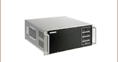
| USB Motion Control 19" Rack Chassis |
| All Thorlabs' Rack System Modules require the use of the APT™ MMR601 or MMR602 Rack System Enclosure. Independent operation of the modules outside the enclosure is not possible. |
Features
- Quiet High Resolution Position Control (for Very Fine Positioning Applications)
- Voltage Ramp and Waveform Generation Capability (for Scanning Applications)
- High Bandwidth (10 kHz) Piezo Positioning
- Auto-Configure Function for Thorlabs Identification-Equipped Piezo Actuators
- User Controlled Digital I/O Port
- User I/O Port (Logic Input/Outputs, Potentiometer Input)
- Full Software Control Suite Supplied
- Intuitive Software Graphical Control Panels
- Extensive ActiveX® Programming Interfaces
- Fully Software Integrated with Other APT™ Family Controllers (Integrated Systems Development)
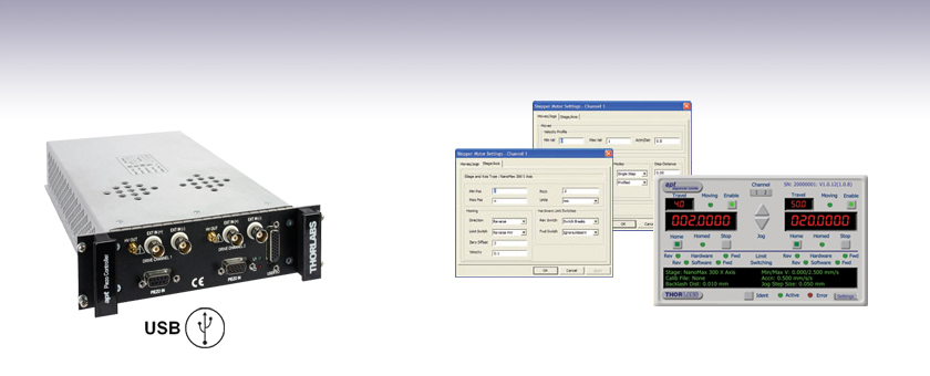
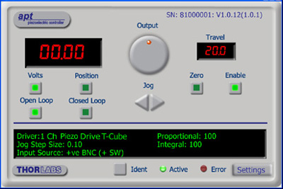
The APT™ MPZ601 piezo driver module is a dual channel high power (75 V, 500 mA) piezo controller. It has been designed to drive the full range of open and closed loop piezo equipped nano-positioning actuators and stages offered by Thorlabs. Equipped with strain gauge feedback circuitry on each channel this unit is able to provide closed loop positioning to the nanometer regime when operated with Thorlabs actuators. In addition flexible software settings make these units highly configurable and therefore suitable for driving a wide range of piezo elements in third party products. A waveform generation capability combined with triggering outputs makes this unit particularly suitable for piezo scanning applications.
This module incorporates the latest high speed digital signal processing (DSP) and low-noise analog electronics technology and has been designed specifically to fit the highly flexible APT MMR601 or MMR602 Motion Control 19" Modular Rack System. Multiple MPZ601 piezo modules can be fitted to this rack system (providing up to 12 channels of operation per rack) to support larger scale critical alignment applications where nanometer level motion control is required with a high axis count.
USB connectivity via the MMR601 or MMR602 Rack Enclosure provides easy plug and play PC operation - multiple modules can be connected to a single PC via standard USB hub technology for multi-axis motion control applications. Coupling this with the very user friendly APT software allows the user to very quickly get up and running in a short space of time – for example all relevant operating parameters are set automatically for Thorlabs piezo actuator products. Advanced custom motion control applications and sequences are also possible using the extensive ActiveX® programming environment described in more detail on the Motion Control Software and APT Tutorials tabs.
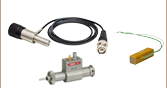
Cabling
Cables for connecting actuators or stages to the controller are shipped with the actuators or stages, not the controller. If you need help identifying the appropriate replacement cable, please contact Tech Support.
| Other Piezo Driver Controllers | |||
|---|---|---|---|
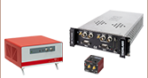
| K-Cube™ Controller and Strain Gauge Reader Single-Channel |
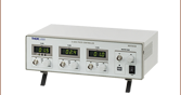
Open Loop Benchtop Controller 1- and 3-Channel |
Closed Loop Benchtop Controller 1- and 3-Channel |
Rack System Module 2-Channel |
Module Specifications
| Specification | Value |
|---|---|
| Piezoelectric Output (SMC Male) - Per Channel | |
| Voltage (Software Control) | 0 to 75 V DC |
| Voltage (External Input) | -10 to 90 V DC |
| Current | 500 mA Max Continuous |
| Stability | 100 ppm Over 24 hours (After 30 mins Warm-Up Time) |
| Noise | <3 mV RMS |
| Typical Piezo Capacitance | 1 to 10 µF |
| Bandwidth | 10 kHz (1 µF Load, 1 Vp-p) |
| Position Feedback (9-Pin D-type Female) - Per Channel | |
| Feedback Type | AC Bridge or 0-10 V Differential DC (SW Selectable) |
| AC Feedback Transducer Type | Strain Gauge |
| AC Detection Method | AC Bridge (18 kHz Excitation) |
| Typical AC Feedback Resolution | 5 nm (for 20 µm Actuator e.g. PAZ005) |
| Auto-Configure | Identification Resistance in Actuator |
| User Input/Output (26-Pin D-type Female) | |
| Potentiometer Input (per channel) | Reference + Wiper (50 kΩ 10 Turn Pots) |
| HV Output Monitor (per channel) | 0 to 10 V DC |
| 4 Digital Inputs | TTL Levels |
| 4 Digital Outputs | Open Collector |
| Trigger Input/Output | TTL |
| Trigger Input Functionality | Triggered Voltage Ramps/Waveforms |
| Trigger Output Functionality | Trigger Generation During Voltage Ramp Output |
| User 5 V (with Ground) 250 mA Max | |
| General | |
| Housing | Single APT™ Rack System Bay |
| Dimensions (W x D x H) | 190 x 270 x 50 mm (7.5" x 10.6" x 2") |
| Weight | 1.5 kg (3.3 lbs) |
User I/O Controller
D-type Female
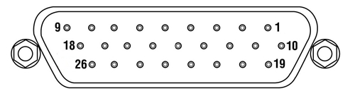
| Pin | Description | Return | Pin | Description | Return | Pin | Description | Return |
|---|---|---|---|---|---|---|---|---|
| 1 | DIG I/P 1a | 19 | 10 | DIG O/P 1a | 19 | 19 | Isolated Groundb | - |
| 2 | DIG I/P 2a | 19 | 11 | DIG O/P 2a | 19 | 20 | Ext Trigger I/P | 22 |
| 3 | DIG I/P 3a | 19 | 12 | DIG O/P 3a | 19 | 21 | Ext Trigger O/P | 22 |
| 4 | DIG I/P 4a | 19 | 13 | DIG O/P 4a | 19 | 22 | Ground | - |
| 5 | Channel 1 RS485 (+) | - | 14 | Channel 2 RS485 (+) | - | 23 | 5 V User O/P (Isolated) | - |
| 6 | Channel 1 RS485 (-) | - | 15 | Channel 2 RS485 (+) | - | 24 | Not Used | - |
| 7 | Not Used | - | 16 | Not Used | - | 25 | Analog or Potentiometer Ground | - |
| 8 | Channel 2 10 V O/Pc | 25 | 17 | Potentiometer Wiper Ch 2 | - | 26 | Potentiometer Reference | 25 |
| 9 | Channel 1 10 V O/Pc | 25 | 18 | Potentiometer Wiper Ch 2 | - |
Piezo Controller
D-type Female
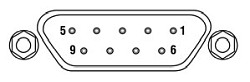
| Pin | Description | Return | Pin | Description | Return | Pin | Description | Return |
|---|---|---|---|---|---|---|---|---|
| 1 | Wheatstone Bridge Excitation | 4 or 6 | 4 | d.c.(+) or Equipment Groundc | - | 7 | d.c.(-) or Actuator ID Signalbc | 4 or 6 |
| 2 | +15Va | 4 or 6 | 5 | Feedback Signal In | 4 or 6 | 8 | RS485 (-) | 9 |
| 3 | -15Va | 4 or 6 | 6 | Equiptment Ground | - | 9 | RS485 (+) | 8 |
Ext In (+) and Ext In (-)
BNC Female
Differential Inputs. The output from the HV amplifier circuit can be set to be controlled, in part, by the differential signal on these two inputs. If the Input Source is set to include a BNC option, the unit sums this differential signal with any other input sources selected (voltage set using the GUI panel 'Output' control and voltage from an external potentiometer).
HV Out
SMC

0 to 75 V, 0 to 250 mA. Provides the drive signal to the piezo actuator.
The APT video tutorials available here fall into two main groups - one group covers using the supplied APT utilities and the second group covers programming the APT System using a selection of different programming environments.
Disclaimer: The videos below were originally produced in Adobe Flash. Following the discontinuation of Flash after 2020, these tutorials were re-recorded for future use. The Flash Player controls still appear in the bottom of each video, but they are not functional.
Every APT controller is supplied with the utilities APTUser and APTConfig. APTUser provides a quick and easy way of interacting with the APT control hardware using intuitive graphical control panels. APTConfig is an 'off-line' utility that allows various system wide settings to be made such as pre-selecting mechanical stage types and associating them with specific motion controllers.
APT User Utility
The first video below gives an overview of using the APTUser Utility. The OptoDriver single channel controller products can be operated via their front panel controls in the absence of a control PC. The stored settings relating to the operation of these front panel controls can be changed using the APTUser utility. The second video illustrates this process.
APT Config Utility
There are various APT system-wide settings that can be made using the APT Config utility, including setting up a simulated hardware configuration and associating mechanical stages with specific motor drive channels. The first video presents a brief overview of the APT Config application. More details on creating a simulated hardware configuration and making stage associations are present in the next two videos.
APT Programming
The APT Software System is implemented as a collection of ActiveX Controls. ActiveX Controls are language-independant software modules that provide both a graphical user interface and a programming interface. There is an ActiveX Control type for each type of hardware unit, e.g. a Motor ActiveX Control covers operation with any type of APT motor controller (DC or stepper). Many Windows software development environments and languages directly support ActiveX Controls, and, once such a Control is embedded into a custom application, all of the functionality it contains is immediately available to the application for automated operation. The videos below illustrate the basics of using the APT ActiveX Controls with LabVIEW, Visual Basic, and Visual C++. Note that many other languages support ActiveX including LabWindows CVI, C++ Builder, VB.NET, C#.NET, Office VBA, Matlab, HPVEE etc. Although these environments are not covered specifically by the tutorial videos, many of the ideas shown will still be relevant to using these other languages.
Visual Basic
Part 1 illustrates how to get an APT ActiveX Control running within Visual Basic, and Part 2 goes on to show how to program a custom positioning sequence.
LabVIEW
Full Active support is provided by LabVIEW and the series of tutorial videos below illustrate the basic building blocks in creating a custom APT motion control sequence. We start by showing how to call up the Thorlabs-supplied online help during software development. Part 2 illustrates how to create an APT ActiveX Control. ActiveX Controls provide both Methods (i.e. Functions) and Properties (i.e. Value Settings). Parts 3 and 4 show how to create and wire up both the methods and properties exposed by an ActiveX Control. Finally, in Part 5, we pull everything together and show a completed LabVIEW example program that demonstrates a custom move sequence.
Part 1: Accessing Online Help
Part 2: Creating an ActiveX Control
Part 3: Create an ActiveX Method
Part 4: Create an ActiveX Property
Part 5: How to Start an ActiveX Control
The following tutorial videos illustrate alternative ways of creating Method and Property nodes:
Create an ActiveX Method (Alternative)
Create an ActiveX Property (Alternative)
Visual C++
Part 1 illustrates how to get an APT ActiveX Control running within Visual C++, and Part 2 goes on to show how to program a custom positioning sequence.
MATLAB
For assistance when using MATLAB and ActiveX controls with the Thorlabs APT positioners, click here.
To further assist programmers, a guide to programming the APT software in LabVIEW is also available here.
Piezo Driver Bandwidth Tutorial
Knowing the rate at which a piezo is capable of changing lengths is essential in many high-speed applications. The bandwidth of a piezo controller and stack can be estimated if the following is known:
- The maximum amount of current the controllers can produce. This is 0.5 A for our BPC Series Piezo Controllers, which is the driver used in the examples below.
- The load capacitance of the piezo. The higher the capacitance, the slower the system.
- The desired signal amplitude (V), which determines the length that the piezo extends.
- The absolute maximum bandwidth of the driver, which is independent of the load being driven.
To drive the output capacitor, current is needed to charge it and to discharge it. The change in charge, dV/dt, is called the slew rate. The larger the capacitance, the more current needed:
For example, if a 100 µm stack with a capacitance of 20 µF is being driven by a BPC Series piezo controller with a maximum current of 0.5 A, the slew rate is given by
Hence, for an instantaneous voltage change from 0 V to 75 V, it would take 3 ms for the output voltage to reach 75 V.
Note: For these calculations, it is assumed that the absolute maximum bandwidth of the driver is much higher than the bandwidths calculated, and thus, driver bandwidth is not a limiting factor. Also please note that these calculations only apply for open-loop systems. In closed-loop mode, the slow response of the feedback loop puts another limit on the bandwidth.
Sinusoidal Signal
The bandwidth of the system usually refers to the system's response to a sinusoidal signal of a given amplitude. For a piezo element driven by a sinusoidal signal of peak amplitude A, peak-to-peak voltage Vpp, and frequency f, we have:
A diagram of voltage as a function of time is shown to the right. The maximum slew rate, or voltage change, is reached at t = 2nπ, (n=0, 1, 2,...) at point a in the diagram to the right:
From the first equation, above:

Thus,
For the example above, the maximum full-range (75 V) bandwidth would be
 .
.
For a smaller piezo stack with 10 times lower capacitance, the results would be 10 times better, or about 1060 Hz. Or, if the peak-to-peak signal is reduced to 7.5 V (10% max amplitude) with the 100 µm stack, again, the result would be 10 times better at about 1060 Hz.
Triangle Wave Signal
For a piezo actuator driven by a triangle wave of max voltage Vpeak and minimum voltage of 0, the slew rate is equal to the slope:
![]() .
.
Or, since f = 1/T:
Square Wave Signal
For a piezo actuator driven by a square wave of maximum voltage Vpeak and minimum voltage 0, the slew rate limits the minimum rise and fall times. In this case, the slew rate is equal to the slope while the signal is rising or falling. If tr is the minimum rise time, then
or
 .
.
For additional information about piezo theory and operation, see the Piezoelectric Tutorials page.
Thorlabs offers two platforms to drive our wide range of motion controllers: our Kinesis® software package or the legacy APT™ (Advanced Positioning Technology) software package. Either package can be used to control devices in the Kinesis family, which covers a wide range of motion controllers ranging from small, low-powered, single-channel drivers (such as the K-Cubes™ and T-Cubes™) to high-power, multi-channel, modular 19" rack nanopositioning systems (the APT Rack System).
The Kinesis Software features .NET controls which can be used by 3rd party developers working in the latest C#, Visual Basic, LabVIEW™, or any .NET compatible languages to create custom applications. Low-level DLL libraries are included for applications not expected to use the .NET framework. A Central Sequence Manager supports integration and synchronization of all Thorlabs motion control hardware.

Kinesis GUI Screen
APT GUI Screen
Our legacy APT System Software platform offers ActiveX-based controls which can be used by 3rd party developers working on C#, Visual Basic, LabVIEW™, or any Active-X compatible languages to create custom applications and includes a simulator mode to assist in developing custom applications without requiring hardware.
By providing these common software platforms, Thorlabs has ensured that users can easily mix and match any of the Kinesis and APT controllers in a single application, while only having to learn a single set of software tools. In this way, it is perfectly feasible to combine any of the controllers from single-axis to multi-axis systems and control all from a single, PC-based unified software interface.
The software packages allow two methods of usage: graphical user interface (GUI) utilities for direct interaction with and control of the controllers 'out of the box', and a set of programming interfaces that allow custom-integrated positioning and alignment solutions to be easily programmed in the development language of choice.
A range of video tutorials is available to help explain our APT system software. These tutorials provide an overview of the software and the APT Config utility. Additionally, a tutorial video is available to explain how to select simulator mode within the software, which allows the user to experiment with the software without a controller connected. Please select the APT Tutorials tab above to view these videos.
Software
Kinesis Version 1.14.49
The Kinesis Software Package, which includes a GUI for control of Thorlabs' Kinesis and APT™ system controllers.
Also Available:
- Communications Protocol
Software
APT Version 3.21.6
The APT Software Package, which includes a GUI for control of Thorlabs' APT™ and Kinesis system controllers.
Also Available:
- Communications Protocol
| Posted Comments: | |
user
(posted 2024-05-07 14:25:45.367) I could not find in the Specs information the bit resolution of the MPZ601 controller. Does Thorlabs have that information available? E.g., what is the smallest voltage step that this controller can achieve? spolineni
(posted 2024-05-15 04:38:53.0) Thank you for your inquiry. The DAC used to generate the output voltage determines the theoretical resolution in open loop. Practical factors, including offset and gain variations, limit this to around 2 mV. Noise and non-linearity of the DAC affect the output, causing unequal step sizes and deviations from the ideal linear progression. These factors collectively determine the complex, multi-variable performance. Mike Jaris
(posted 2021-09-20 14:44:27.423) Why is there a USB symbol next to this device that does not have a USB port?? cwright
(posted 2021-09-21 05:30:12.0) Response from Charles at Thorlabs: Thank you for your query. These modules are intended for use in the MMR601 Rack Enclosure which provides USB connectivity for up to six modules. Laurie
(posted 2009-02-05 15:34:15.0) Response from Laurie at Thorlabs to melsscal: Thank you for your inquiry about our MPZ601, which can work as piezo controller. However, if you want nano track function for auto alignment, youll need to use the MNA601 controller module, which requires either the MMR601 or MMR602 chassis. Each controller module has two channels, so if you wish to control all three channels, youll need two modules. Please contact our technical support department if youd like to discuss your particular application with someone. melsscal
(posted 2009-02-05 03:51:52.0) Can we use MPZ601 with MAX313/M as nano track controller ? |