Products Home
473 nm Multimode Fiber-Coupled Laser Source for Optogenetics
- Multimode Fiber-Coupled Laser Source
- 50.0 mW Output Power
- Ideal for Optogenetics Applications
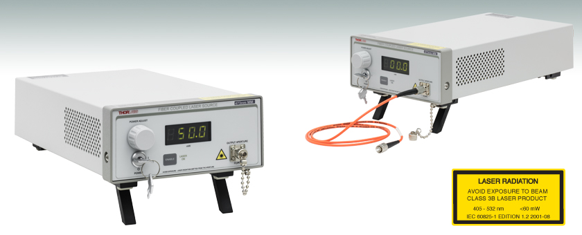
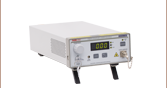
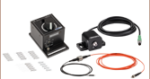
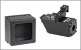
S1FC473MM
473 nm, 50.0 mW
S1FC473MM
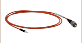
Shown with M43L01
Multimode Patch Cable (Sold Separately)


Please Wait
Features
- Output Wavelength: 473 nm
- Multimode FC/PC Fiber Interface
- 50.0 mW Output Power
- Low Noise, Stable Output
The S1FC473MM Fiber-Coupled Laser provides 50.0 mW of output power and a wavelength of 473 nm, making it an ideal source for many Optogenetics applications. It includes a pigtailed Fabry-Perot laser diode and current controller in a single benchtop unit. The unit's output can also be externally modulated at 5 kHz full depth/30 kHz small signal. The output of the diode is coupled into a FG105UCA multimode fiber terminated at the FC/PC bulkhead. The unit is compatible with our extensive line of Optogenetics Patch Cables and other Optogenetics Equipment.
The front panel includes a display that shows the output power in mW, an on/off key, an enable button, and a knob to adjust the laser power. The back panel includes a BNC input that allows the laser diode drive current to be controlled via an external voltage source and a remote interlock input. All of our fiber-pigtailed lasers utilize an angled fiber ferrule at the internal laser/fiber launch point to minimize reflections back into the laser diode, thereby increasing the stability of the laser diode's output.
Note: The laser must be off when connecting or disconnecting fibers from the device, particularly for power levels above 10 mW.
We also offer Multimode Fiber-Coupled LED Light Sources, as well as other Fiber-Coupled Laser Sources.
Optogenetics Bilateral Stimulation System Schematic
Click on the components or labels for more details on that particular item:
| Item # | S1FC473MM |
|---|---|
| Wavelength | 473 nm |
| Max Output Powera | 50.0 mW |
| Stability | 15 min: ±0.05 dB, 24 hr: ±0.1 dB (After 1 hr Warm-Up at 25 ± 10 °C Ambient) |
| Display Accuracy | ±10 % |
| Setpoint Resolution | 0.1 mW |
| Adjustment Range | ~0 mW to Full Power |
| AC Input | 115 / 230 VAC (Switch Selectable) 50 - 60 Hz |
| Modulation Input | 0 - 5 V = 0 - Full Power, DC or Sine Wave Input Only |
| Modulation Bandwidth | 5 kHz Full Depth of Modulation 30 kHz Small Signal Modulation |
| Fiber | FG105UCA |
| Environmental | |
| Operating Temperature | 15 to 35 °C |
| Storage Temperature | 0 to 50 °C |
Modulation In
BNC Female
0 to 5 V Max, 50 Ω
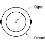
Remote Interlock Input
2.5 mm Mono Phono Jack
Terminals must be shorted either by included plug or user device, i.e. external switch, for laser mode "ON" to be enabled.
Laser Safety and Classification
Safe practices and proper usage of safety equipment should be taken into consideration when operating lasers. The eye is susceptible to injury, even from very low levels of laser light. Thorlabs offers a range of laser safety accessories that can be used to reduce the risk of accidents or injuries. Laser emission in the visible and near infrared spectral ranges has the greatest potential for retinal injury, as the cornea and lens are transparent to those wavelengths, and the lens can focus the laser energy onto the retina.
 |
 |
 |
 |
 |
 |
 |
 |
 |
Safe Practices and Light Safety Accessories
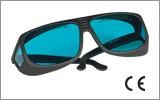
- Laser safety eyewear must be worn whenever working with Class 3 or 4 lasers.
- Regardless of laser class, Thorlabs recommends the use of laser safety eyewear whenever working with laser beams with non-negligible powers, since metallic tools such as screwdrivers can accidentally redirect a beam.
- Laser goggles designed for specific wavelengths should be clearly available near laser setups to protect the wearer from unintentional laser reflections.
- Goggles are marked with the wavelength range over which protection is afforded and the minimum optical density within that range.
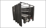
- Laser Safety Curtains and Laser Safety Fabric shield other parts of the lab from high energy lasers.
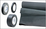
- Blackout Materials can prevent direct or reflected light from leaving the experimental setup area.
- Thorlabs' Enclosure Systems can be used to contain optical setups to isolate or minimize laser hazards.
- A fiber-pigtailed laser should always be turned off before connecting it to or disconnecting it from another fiber, especially when the laser is at power levels above 10 mW.
- All beams should be terminated at the edge of the table, and laboratory doors should be closed whenever a laser is in use.
- Do not place laser beams at eye level.
- Carry out experiments on an optical table such that all laser beams travel horizontally.
- Remove unnecessary reflective items such as reflective jewelry (e.g., rings, watches, etc.) while working near the beam path.
- Be aware that lenses and other optical devices may reflect a portion of the incident beam from the front or rear surface.
- Operate a laser at the minimum power necessary for any operation.
- If possible, reduce the output power of a laser during alignment procedures.
- Use beam shutters and filters to reduce the beam power.
- Post appropriate warning signs or labels near laser setups or rooms.
- Use a laser sign with a lightbox if operating Class 3R or 4 lasers (i.e., lasers requiring the use of a safety interlock).
- Do not use Laser Viewing Cards in place of a proper Beam Trap.
Laser Classification
Lasers are categorized into different classes according to their ability to cause eye and other damage. The International Electrotechnical Commission (IEC) is a global organization that prepares and publishes international standards for all electrical, electronic, and related technologies. The IEC document 60825-1 outlines the safety of laser products. A description of each class of laser is given below:
| Class | Description | Warning Label |
|---|---|---|
| 1 | This class of laser is safe under all conditions of normal use, including use with optical instruments for intrabeam viewing. Lasers in this class do not emit radiation at levels that may cause injury during normal operation, and therefore the maximum permissible exposure (MPE) cannot be exceeded. Class 1 lasers can also include enclosed, high-power lasers where exposure to the radiation is not possible without opening or shutting down the laser. |  |
| 1M | Class 1M lasers are safe except when used in conjunction with optical components such as telescopes and microscopes. Lasers belonging to this class emit large-diameter or divergent beams, and the MPE cannot normally be exceeded unless focusing or imaging optics are used to narrow the beam. However, if the beam is refocused, the hazard may be increased and the class may be changed accordingly. |  |
| 2 | Class 2 lasers, which are limited to 1 mW of visible continuous-wave radiation, are safe because the blink reflex will limit the exposure in the eye to 0.25 seconds. This category only applies to visible radiation (400 - 700 nm). |  |
| 2M | Because of the blink reflex, this class of laser is classified as safe as long as the beam is not viewed through optical instruments. This laser class also applies to larger-diameter or diverging laser beams. |  |
| 3R | Class 3R lasers produce visible and invisible light that is hazardous under direct and specular-reflection viewing conditions. Eye injuries may occur if you directly view the beam, especially when using optical instruments. Lasers in this class are considered safe as long as they are handled with restricted beam viewing. The MPE can be exceeded with this class of laser; however, this presents a low risk level to injury. Visible, continuous-wave lasers in this class are limited to 5 mW of output power. |  |
| 3B | Class 3B lasers are hazardous to the eye if exposed directly. Diffuse reflections are usually not harmful, but may be when using higher-power Class 3B lasers. Safe handling of devices in this class includes wearing protective eyewear where direct viewing of the laser beam may occur. Lasers of this class must be equipped with a key switch and a safety interlock; moreover, laser safety signs should be used, such that the laser cannot be used without the safety light turning on. Laser products with power output near the upper range of Class 3B may also cause skin burns. |  |
| 4 | This class of laser may cause damage to the skin, and also to the eye, even from the viewing of diffuse reflections. These hazards may also apply to indirect or non-specular reflections of the beam, even from apparently matte surfaces. Great care must be taken when handling these lasers. They also represent a fire risk, because they may ignite combustible material. Class 4 lasers must be equipped with a key switch and a safety interlock. |  |
| All class 2 lasers (and higher) must display, in addition to the corresponding sign above, this triangular warning sign. |  |
|
| Posted Comments: | |
| No Comments Posted |
| Quick Links | |||
|---|---|---|---|
| Single-Site Stimulation | |||
| One Light Source to One Cannula Implant | |||
| Multilateral Stimulation | |||
| One Light Source to Two Cannula Implants Using Rotary Joint Splitter | |||
| One or Two Light Sources to Two Cannula Implants | |||
| One Light Source to Seven Cannula Implants | |||
| Two Light Sources into One Dual-Core Cannula Implant | |||
| Illumination | |||
| Fiber-Coupled LEDs and Drivers | |||
Optogenetics Selection Guide
Thorlabs offers a wide range of optogenetics components; the compatibility of these products in select standard configurations is discussed in detail here. Please contact Technical Support for assistance with items outside the scope of this guide, including custom fiber components for optogenetics.
Single-Site Stimulation
One Light Source to One Cannula Implant
The most straightforward method for in vivo light stimulation of a specimen is to use a single fiber optic with a single LED light source. The single wavelength LED is powered by an LED driver, and then the illumination output is fiber-coupled into a patch cable, which connects to the implanted cannula. See the graphics and expandable compatibility tables below for the necessary patch cables and cannulae to create this setup. To choose the appropriate LED and driver, see below or the full web presentation.
Click on Each Component for More Information

Click to See Ø1.25 mm (LC) Ferrule Compatible Patch Cables, Cannulae, and Interconnects
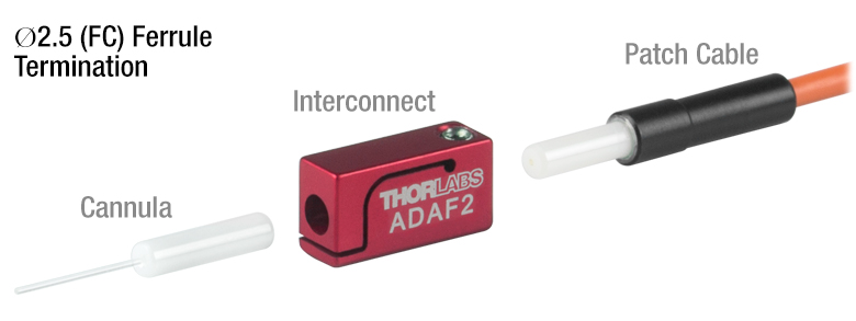
Click to See Ø2.5 mm (FC) Ferrule Compatible Patch Cables, Cannulae, and Interconnects
Multilateral Stimulation
The ability to accurately and simultaneously direct light to multiple locations within a specimen is desired for many types of optogenetics experiments. For example, bilateral stimulation techniques typically target neurons in two spatially separated regions in order to induce a desired behavior. In more complex experiments involving the simultaneous inhibition and stimulation of neurons, delivering light of two different monochromatic wavelengths within close proximity enables the user to perform these experiments without implanting multiple cannulae, which can increase stress on the specimen.
Multilateral stimulation can be achieved with several different configurations depending on the application requirements. The sections below illustrate examples of different configurations using Thorlabs' optogenetics products.
Option 1: One Light Source to Two Cannula Implants Using Rotary Joint Splitter
Thorlabs' RJ2 1x2 Rotary Joint Splitter is designed for optogenetics applications and is used to split light from a single input evenly between two outputs. The rotary joint interface allows connected patch cables to freely rotate, reducing the risk of fiber damage caused by a moving specimen. See the graphic and compatibility table below for the necessary cables and cannulae to create this setup. For LEDs and drivers, see below or the full web presentation.
Click to See Ø1.25 mm (LC) Ferrule Components Recommended for Use with RJ2 Rotary Joint Splitter
Click to See Ø2.5 mm (FC) Ferrule Components Recommended for Use with RJ2 Rotary Joint Splitter
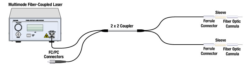
Option 2: One or Two Light Sources to Two Cannula Implants
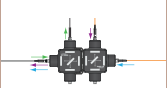
If the intent is for one LED source to connect to two cannulae for simultaneous light modulation, then a bifurcated fiber bundle can be used to split the light from the LED into each respective cannula. For dual wavelength stimulation (mixing two wavelengths in a single cannula) or a more controlled split ratio between cannula, one can use a multimode coupler to connect one or two LEDs to the cannulae. If one cable end is left unused, the spare coupler cable end may be terminated by a light trap. See the graphic and compatibility table below for the necessary cables and cannulae to create this setup. For LEDs and drivers, see below or the full web presentation.
Click on Each Component Below for More Information
Option 3: One Light Sources to Seven Cannula Implants
If the intent is for one LED source to connect to seven cannulae for simultaneous light modulation, then a 1-to-7 fiber bundle can be used to split the light from the LED into each respective cannula. See the graphic and compatibility table below for the necessary cables and cannulae to create this setup. For LEDs and drivers, see below or the full web presentation.
Click on Each Component Below for More Information
Two Light Sources into One Dual-Core Cannula Implant
For bilateral stimulation applications where the two cannulas need to be placed in close proximity (within ~1 mm), Thorlabs offers dual-core patch cables and cannulae that are designed for this specific application. Each core is driven by a separate light source, enabling users to stimulate and/or supress nerve cells in the same region of the specimen. See the graphic and compatibility table below for the necessary cables and cannulae to create this setup. For LEDs and drivers, see below or the full web presentation.
Click on Each Component for More Information
| Part Selection Table (Click Links for Item Description Popup) | |||||||||
|---|---|---|---|---|---|---|---|---|---|
| Common Fiber Properties | |||||||||
| Core Diameter | 200 µm | ||||||||
| Wavelength Range | 400 - 2200 nm | ||||||||
| NA | 0.39 | ||||||||
| Fiber Type | FT200EMT | ||||||||
| Ferrule Stylea | FC (Ø2.5 mm) | ||||||||
| Dual-Core Patch Cable | FC/PC Input | BFY32FL1 | |||||||
| SMA905 Input | BFY32SL1 | ||||||||
| Compatible Mating Sleeve/Interconnect | ADAF1 ADAF2 ADAF4-5 |
||||||||
| Dual-Core Fiber Optic Cannulaec | Stainless Steel | CFM32L10 CFM32L20 |
|||||||
| LED Item # | Wavelengtha | Typical Opsin | Output Powerb | Color |
|---|---|---|---|---|
| M405F3c | 405 nm | mmilCFP, hcriGFP | 3.7 mW | UV |
| M430F1 | 430 nm | ChR2 | 7.5 mW | Violet |
| M455F3 | 455 nm | ChIEF, bPAC | 24.5 mW | Royal Blue |
| M470F4 | 470 nm | ChR2, ChR2-SFO | 20 mW | Blue |
| M490F4 | 490 nm | Rh-CT, ChR2 (E123A) | 2.8 mW | Blue |
| M505F3 | 505 nm | ChRGR, Opto-α1AR, Opto-β2AR | 11.7 mW | Cyan |
| M530F3 | 530 nm | C1V1, VChR1 | 9.6 mW | Green |
| M565F3 | 565 nm | Arch, VChR1-SFO | 13.5 mW | Lime |
| M595F2 | 595 nm | ChR2-SFO, eNpHR3.0 | 11.5 mW | Amber |
| M625F2 | 625 nm | ReChR | 17.5 mW | Red |
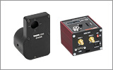
Illumination
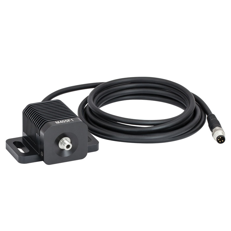
Click to Enlarge
M405F1
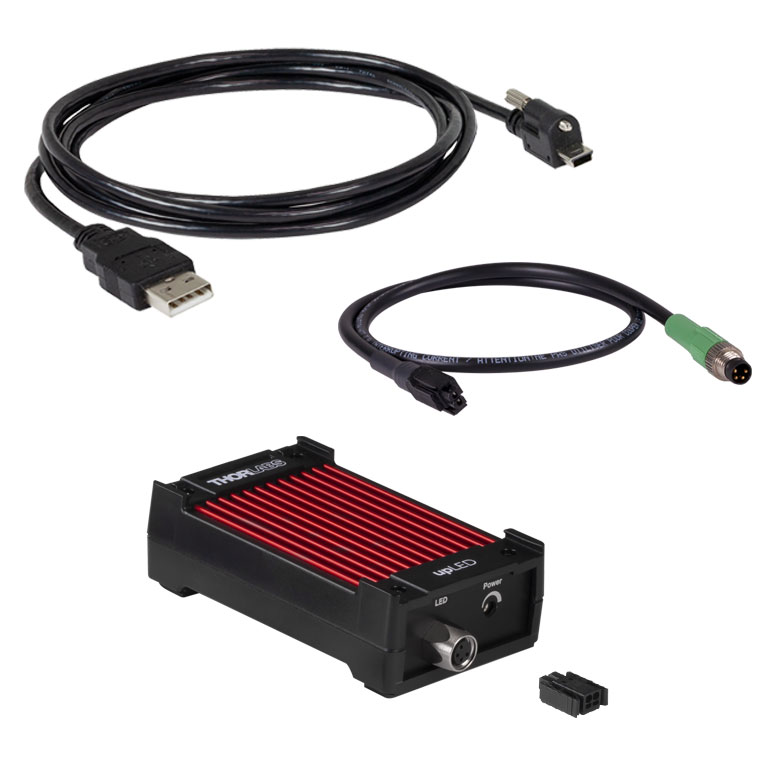
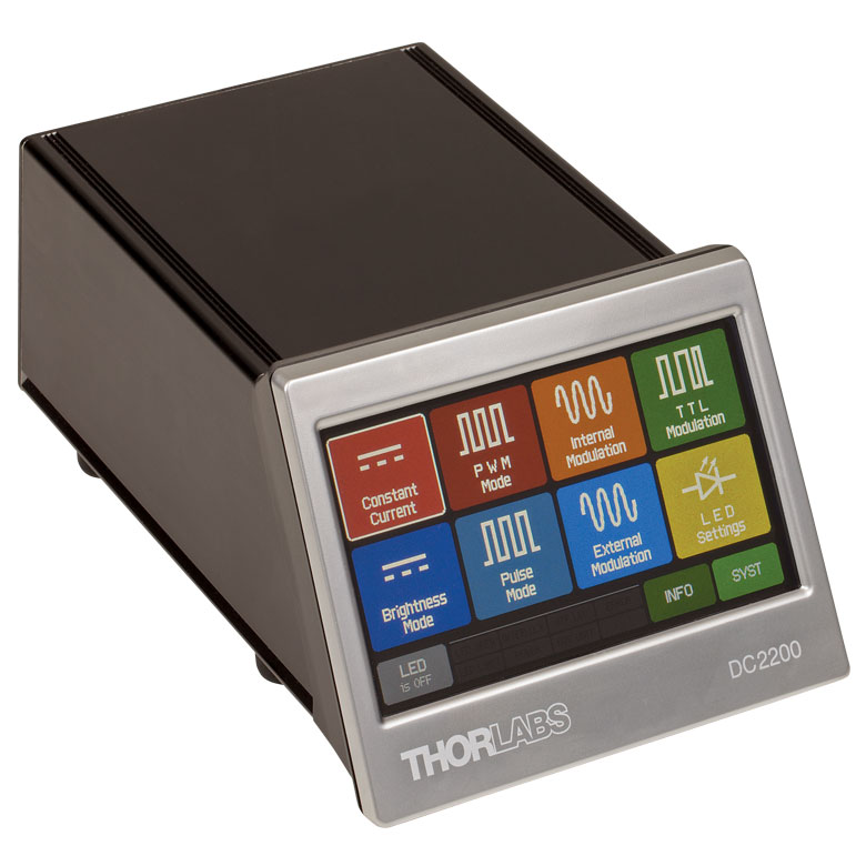
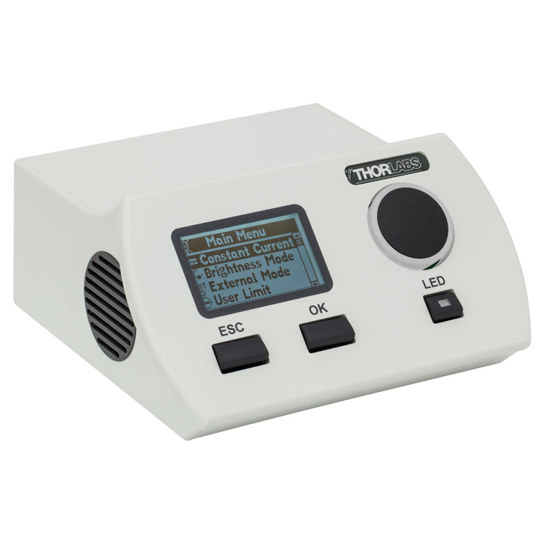
Fiber-Coupled LEDs and Drivers
Our fiber-coupled LEDs are ideal light sources for optogenetics applications. They feature a variety of wavelength choices and a convenient interconnection to optogenetics patch cables. Thorlabs offers fiber-coupled LEDs with nominal wavelengths ranging from 280 nm to 1050 nm. See the table to the right for the LEDs with the most popular wavelengths for optogenetics. A table of compatible LED drivers can be viewed by clicking below.