Products Home
Interconnects and Mating Sleeves for Fiber Optic Cannulae

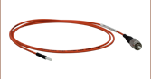
BFY32FL1
Dual Core Patch Cable with FC/PC
Connectors on Split Ends and Ø2.5 mm
Stainless Steel Ferrule on Common End
ADAF1
Ceramic Split Mating Sleeve
Ø2.5 mm Dual-Core Stainless Steel Ferrule with Guide Pin
- Connect Optogenetics Patch Cables and Cannulae
- Quick-Release Interconnects Allow Simple,
Low-Force Connections - Lightweight Split Mating Sleeves
ADAF2
Interconnect for
Ø2.5 mm Ferrules
ADAF4-5
Ø2.5 mm Phosphor Bronze
Mating Sleeve (Pack of 5)
ADAL1
Ø1.25 mm Ceramic
Mating Sleeve
ADAL3 Quick-Release Interconnect Mating a Multimode Patch Cable and a Ø1.25 mm Cannula
ADAL3
Interconnect for
Ø1.25 mm Ferrules


Please Wait
Thorlabs offers interconnects and mating sleeves for making connections between our line of optogenetics patch cables and fiber optic cannulae, for applications such as fiber photometry. These ferrule-mating components provide low-loss coupling and are compatible with both stainless steel and ceramic (zirconia) ferrules. The interconnect is designed to facilitate easy connections and disconnections from an implanted cannula, requiring <20% of the force needed to disconnect from mating sleeves. On the other hand, mating sleeves are preferred for very lightweight, low-profile connections between a patch cable and cannula.
Optogenetics Product Family for In Vivo Applications
Thorlabs offers a wide variety of products designed to support in vivo optogenetics applications. Please visit the OG Selection Guide tab above to see a full listing of available products for different applications.

This tab contains instructions for using an interconnect to mate an optogenetics patch cable with a Ø1.25 mm or Ø2.5 mm ferrule to a cannula of the same diameter. Please see the animation below for an illustration of the installation process detailed here.
Connecting the Patch Cable
Insert the patch cable ferrule into the interconnect on the side with the stainless steel setscrew. To secure the patch cable, use the included hex key [0.028" for the ADAL3 and 0.05" (1.3 mm) for the ADAF2] to tighten the setscrew onto the inserted ferrule.
- Ensure that the patch cable ferrule tip is clean and free of dust; we recommend our canned compressed air.
- For best results, the patch cable should be inserted past the setscrew and about halfway into the ceramic mating component within the interconnect.
Connecting the Cannula
To connect to a cannula, gently squeeze the interconnect from both sides where indicated by the engraving, then insert the cannula ferrule into the open end until physical contact with the patch cable ferrule is achieved. To lock the cannula in place, simply let go of the interconnect.
- Check that the ferrule tip of the cannula is clean and free of dust.
- If the cannula is already implanted or glued into position, adjust the cable-side ferrule, if necessary, to ensure physical contact between the ferrules.
- When using the dual core cannula and patch cable, please note the orientation of the patch cable for alignment purposes.
Disconnecting the Cannula and Patch Cable
To disconnect the interconnect from a cannula, squeeze the interconnect and gently pull the interconnect until disconnected from the cannula. The patch cable can be released by loosening the setscrew with the included hex key.
| Posted Comments: | |
user
(posted 2023-10-17 15:04:03.777) Why would a customer choose a phosphor bronze mating sleeve over a zirconia mating sleeve? ksosnowski
(posted 2023-10-18 04:39:46.0) Thanks for reaching out to Thorlabs. Radial forces on the ceramic sleeve may result in a crack, while with phosphor bronze the material is more ductile so would begin to bend instead. The friction inside the bronze sleeve is lower which results in a lower disconnect force as seen in the performance plots on this webpage. I have reached out directly to discuss your application further. Manuel Esguerra
(posted 2022-11-03 14:23:42.113) Does the second hole (not setscrew) on the side of the ADAL3 interconnect serve a purpose? We are seeing light through this hole with some fiber/cannula pairs. jgreschler
(posted 2022-11-16 11:38:22.0) Thank you for reaching out to Thorlabs. Having light leaking out of the side of the interconnect is a sign that the fiber-to-fiber connection is not good, I have reached out to you directly to discuss methods to improve that connection. Nate Miska
(posted 2021-10-15 08:50:47.853) Interconnect device is frequently difficult to insert ferrules. Internal mechanism has already broken for one of the ADAL3 that was purchased only a couple months ago. Not a particularly effective or user-friendly design, IMO. cdolbashian
(posted 2021-10-28 04:10:38.0) Thank you for contacting us at thorlabs with this feedback! I am sorry to hear that you are not satisfied with the performance of this device. I have reached out to you directly to discuss your application and usage specifications. We take this feedback seriously, and I will pass it along internally, as we are always "hungry for your thoughts". |
| Quick Links | |||
|---|---|---|---|
| Single-Site Stimulation | |||
| One Light Source to One Cannula Implant | |||
| Multilateral Stimulation | |||
| One Light Source to Two Cannula Implants Using Rotary Joint Splitter | |||
| One or Two Light Sources to Two Cannula Implants | |||
| One Light Source to Seven Cannula Implants | |||
| Two Light Sources into One Dual-Core Cannula Implant | |||
| Illumination | |||
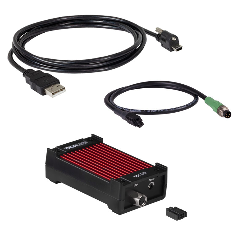
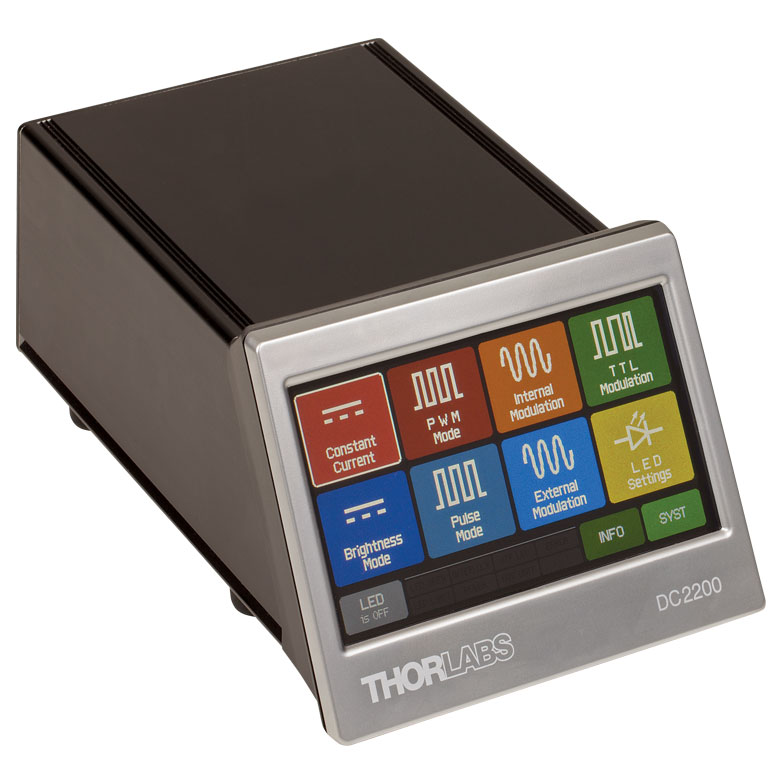
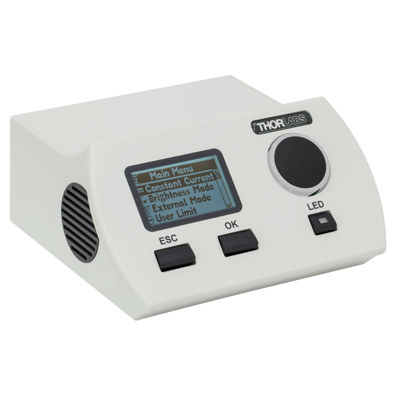
| Fiber-Coupled LEDs and Drivers | |||
Optogenetics Selection Guide
Thorlabs offers a wide range of optogenetics components; the compatibility of these products in select standard configurations is discussed in detail here. Please contact Technical Support for assistance with items outside the scope of this guide, including custom fiber components for optogenetics.
Single-Site Stimulation
One Light Source to One Cannula Implant
The most straightforward method for in vivo light stimulation of a specimen is to use a single fiber optic with a single LED light source. The single wavelength LED is powered by an LED driver, and then the illumination output is fiber-coupled into a patch cable, which connects to the implanted cannula. See the graphics and expandable compatibility tables below for the necessary patch cables and cannulae to create this setup. To choose the appropriate LED and driver, see below or the full web presentation.
Click on Each Component for More Information
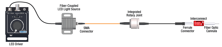

Click to See Ø1.25 mm (LC) Ferrule Compatible Patch Cables, Cannulae, and Interconnects
Click to See Ø2.5 mm (FC) Ferrule Compatible Patch Cables, Cannulae, and Interconnects
Multilateral Stimulation
The ability to accurately and simultaneously direct light to multiple locations within a specimen is desired for many types of optogenetics experiments. For example, bilateral stimulation techniques typically target neurons in two spatially separated regions in order to induce a desired behavior. In more complex experiments involving the simultaneous inhibition and stimulation of neurons, delivering light of two different monochromatic wavelengths within close proximity enables the user to perform these experiments without implanting multiple cannulae, which can increase stress on the specimen.
Multilateral stimulation can be achieved with several different configurations depending on the application requirements. The sections below illustrate examples of different configurations using Thorlabs' optogenetics products.
Option 1: One Light Source to Two Cannula Implants Using Rotary Joint Splitter
Thorlabs' RJ2 1x2 Rotary Joint Splitter is designed for optogenetics applications and is used to split light from a single input evenly between two outputs. The rotary joint interface allows connected patch cables to freely rotate, reducing the risk of fiber damage caused by a moving specimen. See the graphic and compatibility table below for the necessary cables and cannulae to create this setup. For LEDs and drivers, see below or the full web presentation.
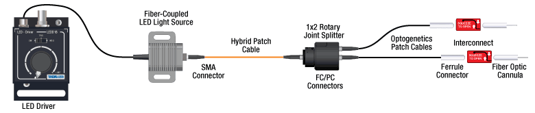
Click to See Ø1.25 mm (LC) Ferrule Components Recommended for Use with RJ2 Rotary Joint Splitter
Click to See Ø2.5 mm (FC) Ferrule Components Recommended for Use with RJ2 Rotary Joint Splitter
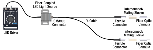
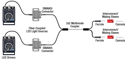
Option 2: One or Two Light Sources to Two Cannula Implants
If the intent is for one LED source to connect to two cannulae for simultaneous light modulation, then a bifurcated fiber bundle can be used to split the light from the LED into each respective cannula. For dual wavelength stimulation (mixing two wavelengths in a single cannula) or a more controlled split ratio between cannula, one can use a multimode coupler to connect one or two LEDs to the cannulae. If one cable end is left unused, the spare coupler cable end may be terminated by a light trap. See the graphic and compatibility table below for the necessary cables and cannulae to create this setup. For LEDs and drivers, see below or the full web presentation.
Click on Each Component Below for More Information
Option 3: One Light Sources to Seven Cannula Implants
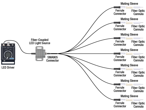
If the intent is for one LED source to connect to seven cannulae for simultaneous light modulation, then a 1-to-7 fiber bundle can be used to split the light from the LED into each respective cannula. See the graphic and compatibility table below for the necessary cables and cannulae to create this setup. For LEDs and drivers, see below or the full web presentation.
Click on Each Component Below for More Information
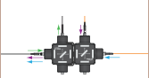
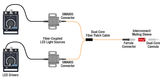
Two Light Sources into One Dual-Core Cannula Implant
For bilateral stimulation applications where the two cannulas need to be placed in close proximity (within ~1 mm), Thorlabs offers dual-core patch cables and cannulae that are designed for this specific application. Each core is driven by a separate light source, enabling users to stimulate and/or supress nerve cells in the same region of the specimen. See the graphic and compatibility table below for the necessary cables and cannulae to create this setup. For LEDs and drivers, see below or the full web presentation.
Click on Each Component for More Information
| Part Selection Table (Click Links for Item Description Popup) | |||||||||
|---|---|---|---|---|---|---|---|---|---|
| Common Fiber Properties | |||||||||
| Core Diameter | 200 µm | ||||||||
| Wavelength Range | 400 - 2200 nm | ||||||||
| NA | 0.39 | ||||||||
| Fiber Type | FT200EMT | ||||||||
| Ferrule Stylea | FC (Ø2.5 mm) | ||||||||
| Dual-Core Patch Cable | FC/PC Input | BFY32FL1 | |||||||
| SMA905 Input | BFY32SL1 | ||||||||
| Compatible Mating Sleeve/Interconnect | ADAF1 ADAF2 ADAF4-5 |
||||||||
| Dual-Core Fiber Optic Cannulaec | Stainless Steel | CFM32L10 CFM32L20 |
|||||||
| LED Item # | Wavelengtha | Typical Opsin | Output Powerb | Color |
|---|---|---|---|---|
| M385F1c | 385 nm | EBFP, moxBFP | 10.7 mW | UV |
| M405F1c | 405 nm | mmilCFP, hcriGFP | 3.7 mW | UV |
| M430F1 | 430 nm | ChR2 | 7.5 mW | Violet |
| M455F3 | 455 nm | ChIEF, bPAC | 24.5 mW | Royal Blue |
| M505F3 | 505 nm | ChRGR, Opto-α1AR, Opto-β2AR | 11.7 mW | Cyan |
| M530F2 | 530 nm | C1V1, VChR1 | 9.6 mW | Green |
| M565F3 | 565 nm | Arch, VChR1-SFO | 13.5 mW | Lime |
| M595F2 | 595 nm | ChR2-SFO, eNpHR3.0 | 11.5 mW | Amber |
| M625F2 | 625 nm | ReChR | 17.5 mW | Red |
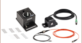
Illumination
Click to Enlarge
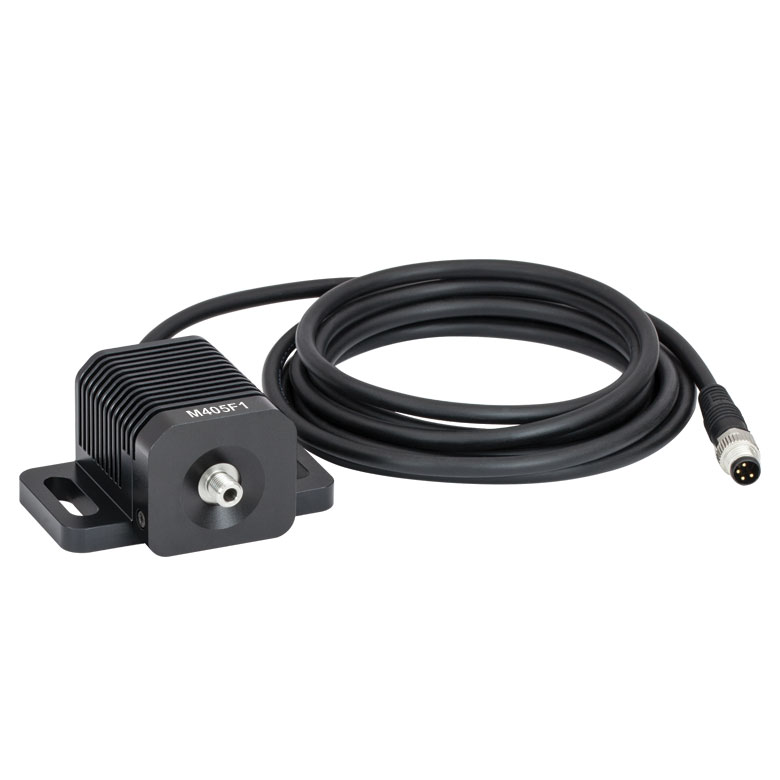
M405F1
Fiber-Coupled LEDs and Drivers
Our fiber-coupled LEDs are ideal light sources for optogenetics applications. They feature a variety of wavelength choices and a convenient interconnection to optogenetics patch cables. Thorlabs offers fiber-coupled LEDs with nominal wavelengths ranging from 280 nm to 1050 nm. See the table to the right for the LEDs with the most popular wavelengths for optogenetics. A table of compatible LED drivers can be viewed by clicking below.


 Zoom
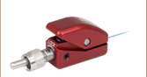
ZoomQuick-Release Interconnect Usage

Click to Enlarge
Cannulae can be inserted or removed with a single hand.
- Quick-Release Interconnects for Mating Ø1.25 mm or Ø2.5 mm Ferrules
- Easily Secure and Disconnect Ferrule with One-Handed Squeeze Operation
- Low-Force Disconnections Minimize Stress on Specimen
- Constructed from Virtually Nonmagnetic Materials
- Minimal Light Leakage
- Lightweight (≤1 g)
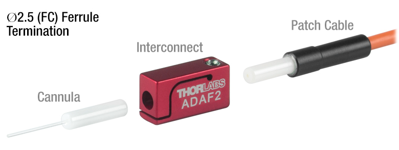
Thorlabs' Quick-Release Interconnects are easy-to-use and reliable solutions for mating optogenetics patch cables and cannulae. These interconnects offer <1.0 dB (<21%) insertion loss and minimal light leakage at the interconnect interface, preventing stray light from distracting a specimen. The quick-release mechanism requires <35% of the force to connect or disconnect compared to mating sleeves, significantly reducing stress on a specimen when mating to a patch cable. As shown in the photo to the left, the interconnects can be operated using a single hand which ensures hassle-free mating to an implanted cannula.
Click to Enlarge
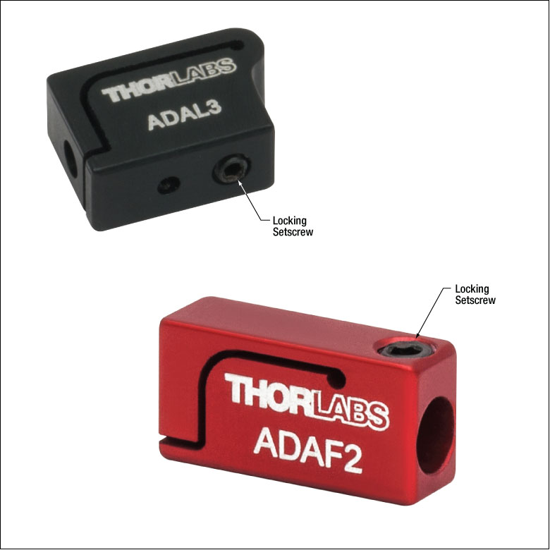
Each interconnect features a locking setscrew to secure the inserted ferrule.
As seen in the animation to the right, an interconnect holds a patch cable ferrule on one end using a cup-point setscrew that does not damage the ferrule surface, and holds a cannula on the other end using a quick-release squeeze mechanism. First, insert a patch cable ferrule into the interconnect and secure by tightening the setscrew using the included hex key. Then, squeeze the quick-release lever and insert the cannula until it makes physical contact with the ferrule. Finally, release the lever to lock the cannula into place. The interconnect is engraved to indicate where squeeze pressure should be applied. To release the cannula (or disconnect from an implanted cannula), squeeze the quick-release lever and pull the interconnect away from the cannula; only light force is needed to disconnect the interconnect. Please see the Interconnect Usage tab above for additional guidelines.
These interconnects are designed to be used with our optogenetics patch cables and cannulae and are not intended for use with patch cables terminated with standard connectors.
| Item # | Compatible Ferrule Size |
Insertion Loss | Length | Weight | Disconnect Forcea |
|---|---|---|---|---|---|
| ADAL3 | 1.25 mm Outer Diameter | <1.0 dB Typical Loss (Multimode)b | 9.4 mm | 0.4 g | <0.89 N (<0.2 lbf) Typicalc |
| ADAF2 | 2.5 mm Outer Diameter | <1.0 dB Typical Loss (Multimode)d | 13.6 mm | 1 g | <4.4 N (<1.0 lbf) Typicale |

 Zoom
Zoom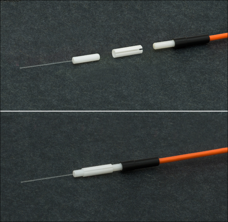
Click for Details
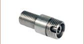
In the photo above, the ADAF1 is used to connect a cannula with a 2.5 mm ferrule to the ferrule end of a M81L01 patch cable.
Click to Enlarge
ADAF1 Mating Sleeve with Optogenetics Patch Cable and Cannula
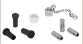
- Split Mating Sleeves for Ø1.25 mm and Ø2.5 mm Ferrules
- Ceramic (Zirconia) or Phosphor Bronze
- Connect Optogenetics Patch Cables and Cannulae
- Split Sleeves are Very Lightweight (≤0.26 g)
- Sold Individually or in Packs of 5
Our mating sleeves are low-profile options for connecting our optogenetics patch cables with ferrule connectors to our implantable fiber optic cannulae (see photo to the right). Additionally, they are capable of connecting any terminated fiber with a Ø1.25 mm or Ø2.5 mm ferrule, such as LC/PC, FC/PC, ST®*/PC, SC/PC, and MU/PC connectors.
These mating sleeves are compatible with both stainless steel and ceramic patch cables and cannulae. Cannulae and patch cables with different ferrule materials can be mixed and matched without significant additional signal losses.
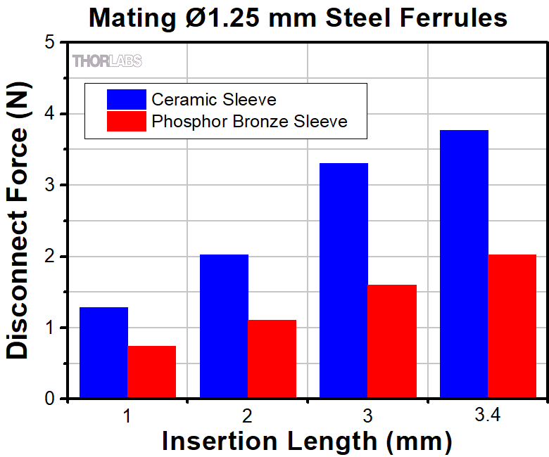
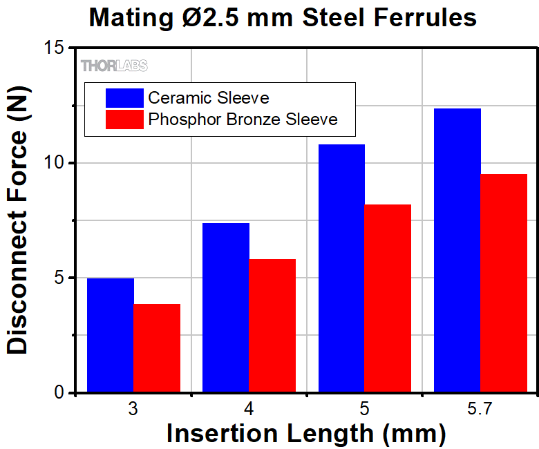
Ceramic mating sleeves are available individually or in packages of five. Phosphor bronze mating sleeves are also available in packs of five. Ceramic can be easily cleaned in an autoclave, while phosphor bronze is slightly malleable and can be disconnected with less force as shown in the graphs below.*ST® is a registered trademark of Lucent Technologies, Inc.
| Item # Prefix | Compatible Ferrule Size | Insertion Loss | Length | Weight | Disconnect Force | Comparison Graphs | Material |
|---|---|---|---|---|---|---|---|
| ADAL1 | 1.25 mm Outer Diameter | <0.5 dB Typical (SM)a <1.0 dB Typical (MM)b |
6.8 mm | 0.05 g | 4.23 N (0.95 lbf) Typicalc | Ceramic (Zirconia) | |
| ADAL4 | 0.06 g | 3.15 N (0.71 lbf) Typicalc | Phosphor Bronze | ||||
| ADAF1 | 2.5 mm Outer Diameter | <0.2 dB Typical (SM)d <1.0 dB Typical (MM)e |
11.4 mm | 0.18 g | 25.83 N (5.81 lbf) Typicalf | Ceramic (Zirconia) | |
| ADAF4 | 0.26 g | 23.53 N (5.29 lbf) Typicalf | Phosphor Bronze |