Kinematic Platform Mounts
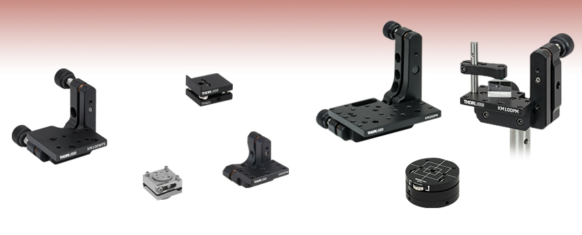
- Mounts for Prisms, Fixed Optic Mounts, or Beamsplitters
- Mount Specifically Designed for Thorlabs' Wavefront Sensors
- Vertical or Horizontal Mounting Surfaces
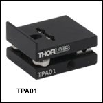
TPA01
Pitch Adjuster for Fixed Optic Mounts
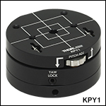
KPY1
Ø2" (Ø50.8 mm) Platform
Pitch/Yaw Mount
Application Idea
KM100PM Shown in the Right-Handed Configuration with a PM3 Clamping Arm and PS610 Prism
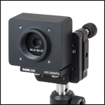
KM100WFS
#8 and M3 Through Holes for Mounting Wavefront Sensors
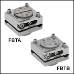
FBTB
Glue-In Mount for 5 mm Cube Optics
KM200PM
6-32 Taps, 8-32 Taps,
and #8 Through Holes
KM05PM
6-32 and 4-40 Taps

Please Wait
Features
- Kinematic Vertical or Horizontal Mounting Surfaces
- Mount Prisms, Beamsplitters, Non-Standard Optics, Fixed Optic Mounts, or Wavefront Sensors
- ±3°, ±4°, or ±5° of Tip and/or Tilt Adjustment
- Kinematic Platform Options:
- Mounting Platform Plate Perpendicular or Parallel to Adjusters With Mounting Holes for Clamping Arms
- Tip/Tilt and Rotation, Glue-In Platform Mount for Small Optics
- Pitch and Yaw Mount with Ø2" (Ø50.8 mm) Platform
- One-Axis Pitch Adapter with #8 Counterbored Slot for Optic Mounts
- Compatible with Optical Posts
Thorlabs offers kinematic platform mounts for prisms, wavefront sensors, small optics, and fixed optic mounts. The mounts feature one, two, or three axes of ±3°, ±4°, or ±5° tip/tilt adjustment.
Platform and prism mounts have two axes of adjustment and feature a mounting platform with 4-40 (M3) 6-32 (M4) taps to mount our PM3(/M) and PM4(/M) Clamping Arms. The back plate of each of these mounts have a 4-40 (M3) tap for mounting to our Mini-Series Optical Posts or have #8 (M4) through holes or 8-32 (M4) taps for mounting to a Ø1/2" post. Platform mounts provide a large mounting area and a beam path unobstructed by kinematic adjusters. The prism mounts offer a more compact profile. THe KM100PM(/M) and KM200PM(/M) can be configured in left- or right-handed orientations by repositioning the platform. We also offer a mini-series version, and version with mounting holes designed to hold our Wavefront Sensors.
Glue-In Platform Mounts are designed for 1/2" wide plate optics or 5 mm cubes. They feature three kinematic adjusters for tip and tilt and a separate adjuster for rotation. Each mount offers an 8-32 (M4) tap for post mounting.
The Kinematic Pitch/Yaw Mount provides ±3° of pitch adjustment on a platform that can be rotated 360°. It consists of a magnetically coupled top section and base, with a 1/4" (M6) clearance hole in the bottom for mounting to a post, optical table, or breadboard.
The Kinematic Pitch Adapter is designed to adjust the pitch of a standard optic mount. It has two 8-32 (M4) tapped holes for post mounting vertically or horizontally and a #8 counterbored slot for attaching fixed optic mounts.
Reading a Vernier Scale on a Linear Main Scale
Vernier scales are typically used to add precision to standard, evenly divided scales (such as the scales on Thorlabs' rotation, goniometric, or translation mounts). A vernier scale has found common use in many precision measurement instruments, the most common being calipers and micrometers. The vernier scale uses two scales side-by-side: the main scale and the vernier scale. The direct vernier scale has a slightly smaller spacing between its tick marks owing to the vernier scale having N ticks for every N - 1 ticks on the main scale. Hence, the lines on the main scale will not line up with all the lines on the vernier scale. Only one line from the vernier scale will match well with one line of the main scale, and that is the trick to reading a vernier scale.
Figures 130A through 130C show a linear vernier scale system for three different situations. In each case, the scale on the left is the main scale, while the small scale on the right is the vernier scale. When reading a vernier scale, the main scale is used for the gross number, and the vernier scale gives the precision value. In this manner, a standard ruler or micrometer can become a precision instrument.
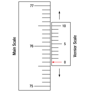
The 0 on the vernier scale is the "pointer" (marked by a red arrow in Figures 130A through 130E) and will indicate the main scale reading. In Figure 130A we see the pointer is lined up directly with the 75.6 line. Notice that the only other vernier scale tick mark that lines up well with the main scale is 10. Since the pointer lines up with the main scale’s 75.6, the reading from Figure 130A is 75.60 (in whatever units the instrument measures).
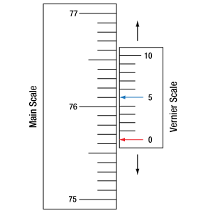
That is essentially all there is to reading a vernier scale. It's a very straightforward way of increasing the precision of a measurement instrument. To expound, let’s look at Figure 130B. Here we see that the pointer is no longer aligned with a line on the main scale, but instead it is slightly above 75.6 and below 75.7; thus, the gross measurement is 75.6. The first vernier line that coincides with a main scale line is the 5, shown with a blue arrow. The vernier scale gives the final digit of precision; since the 5 is aligned to the main scale, the precision measurement for Figure 130B is 75.65.
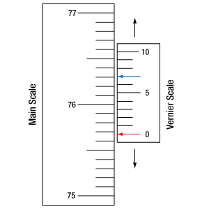
Since this vernier scale is 10% smaller than the main scale, moving the vernier scale by 1/10 of the main scale will align the next vernier marking. This asks the obvious question: what if the measurement is within the 1/10 precision of the vernier scale? Figure 130C shows just this. Again, the pointer line is in between 75.6 and 75.7, yielding the gross measurement of 75.6. If we look closely, we see that the vernier scale 7 (marked with a blue arrow) is very closely aligned to the main scale, giving a precision measurement of 75.67. However, the vernier scale 7 is very slightly above the main scale mark, and we can see that the vernier scale 8 (directly above 7) is slightly below its corresponding main scale mark. Hence, the scale on Figure 130C could be read as 75.673 ± 0.002. A reading error of about 0.002 would be appropriate for
this instrument.
Click to Enlarge
Figure 130A An example of how to read a vernier scale. The red arrow indicates what is known as the pointer. Since the tick mark labeled 10 on the vernier scale aligns with one of the tick marks on the main scale, this vernier scale is reading 75.60 (in whatever units the instrument measures).
Click to Enlarge
Figure 130B The red arrow indicates the pointer and the blue arrow indicates the vernier line that matches the main scale. This scale reads 75.65.
Click to Enlarge
Figure 130C The red arrow indicates the pointer, and the blue arrow indicates the vernier line that matches the main scale. This scale reads 75.67 but can be accurately read as
75.673 ± 0.002.
Reading a Vernier Scale on a Rotating Main Scale
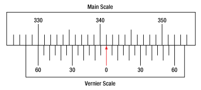
The vernier scale may also be used on rotating scales where the main scale and vernier scale do not share units. Figures 130D and 130F show a vernier scale system for two different situations where the main scale is given in degrees and the vernier scale has ticks every 5 arcmin (60 arcmin = 1°). In each case, the scale on the top is the main scale, while the small scale on the bottom is the vernier scale.
In Figure 130D we see the pointer is lined up directly with the 341° line. Notice that the only other vernier scale tick marks that line up well with the main scale are ±60 arcmin. Since the pointer lines up with the main scale at 341°, the reading from Figure 130D is 341.00°.
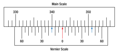
There are two ways to determine the reading if the zero on the vernier scale line is between two lines of the main scale. For the first method, take the line on the left side of the pointer on the vernier scale and subtract that value (in arcmin) from the value on the main scale that is to the right on the main scale. As an example, in Figure 130E the vernier pointer is between 342° and 343°; using the left blue arrow of the vernier scale results in
As we've seen here, vernier scales add precision to a standard scale measurement. While it takes a bit of getting used to, with a little practice, reading these scales is fairly straightforward. Vernier scales, whether they are direct or retrograde*, are read in the same fashion.
*A retrograde vernier scale has a larger spacing between its tick marks with N ticks for every N + 1 ticks on the main scale.
Click to Enlarge
Figure 130D An example of a vernier scale where the main scale and the vernier scale are in different units (degrees and arcmins, respectively). The red arrow indicates the pointer. This scale reads 341.00°.
Click to Enlarge
Figure 130E The red arrow indicates the pointer and the blue arrows give the precision value from the vernier scale.
This scale reads 342.75°.
| Posted Comments: | |
何 张
(posted 2024-04-27 20:56:41.043) Can you tell me about the maximum plate load capacity of KM100B jdelia
(posted 2024-05-03 04:15:16.0) Thank you for contacting Thorlabs. Since we have not formally characterized a load capacity for this mount, I have reached out to you directly to inquire about the details of your application, so we may look into whether your desired load would be suitable for the KM100B. Daniel Dickinson
(posted 2023-08-12 13:23:39.46) The mounting platform for the KPY1 has 8/32 mounting taps on two sides of the square (made by the witness lines). Can you make a custom version that has 8/32 mounting taps on all four sides of the square? And if so, how much would this cost? Thanks. cdolbashian
(posted 2023-08-30 11:41:17.0) Thank you for reaching out to us with this inquiry. I have reached out to you directly to discuss your application, alternative stock parts, as well as the feasibility of such a custom. Hannah Manetsch
(posted 2023-03-30 11:35:39.263) The KM200PM mount has cm spacing between mounting holes despite being the "imperial" version, which makes compatibility tough with other plates, etc. If possible, it would be helpful to have an imperial version with 1/2" spacing between the mounting through-holes. cdolbashian
(posted 2023-04-13 10:34:25.0) Thank you for reaching out to us Hannah! I have reached out to you directly to clarify your question, as it seems like this imperial stage has standard 0.25",0.5", and 1" spacing between tapped holes. Alternatively, what might be confusing you is the 0.4" spacing on the tapped holes used for the clamping arms on the device. Venkata Pathipati
(posted 2022-12-20 14:52:35.663) PR005/M
KM100B/B
We're using above items in our design, Can you tell me about material used to make these?
Thanks jdelia
(posted 2022-12-28 10:14:20.0) Thank you for contacting Thorlabs. These devices contain several materials, with the main body of each being made of anodized 6061-T6 aluminum. I have reached out to you directly to clarify exactly what information you require. user
(posted 2020-10-26 13:05:35.203) Can platforms be purchased separately please, this would help us YLohia
(posted 2020-10-26 04:33:31.0) Platforms (and other component-level items) can be purchased separately by emailing techsupport@thorlabs.com. user
(posted 2020-09-25 01:38:55.113) I want to use a kinematic platform mount for FFM1 or CM1-DCH, as I want to adjust the tip/tilt of a dichroic which is put on the FFM1. It looks like the tapped holes are not matched with either FFM1 or CM1-DCH. Is there any product that can help me do that? llamb
(posted 2020-09-28 04:21:13.0) Thank you for contacting Thorlabs. The CM1-DCH only features one tapped hole on its bottom, intended for mounting directly to an optical post. However, this could still be used with a kinematic platform mount like the KM200B for instance, and a #8-32 cap screw. Alternatively, the FFM1 can be mounted onto our B4C kinematic cage cube platform to achieve tip/tilt of your dichroic filter, and then that B4C can be mounted into either our C4W or C6W cage cube. Roger Ding
(posted 2020-09-13 14:51:49.75) For the PM3-, PM4-, PM5-series mounts, I think it'd be convenient having the machined clearance that allowing the set screw to stick out below the arm to be on both sides instead of just one so that the arm is reversible. This would allow the user to orient the arm's locking screw in a convenient direction (e.g., not blocked by other parts of the mount). llamb
(posted 2020-09-15 04:22:23.0) Thank you for your feedback. We will consider this suggestion further to make the PM- series clamping arms more versatile. h.wu
(posted 2018-06-17 22:46:50.777) I would like to know if it is possible to purchase FBTA/M with customized silver mirrors?
12.7 mm × 12.7 mm × 1 mm
6.35 mm × 6.35 mm × 1 mm
Thanks, YLohia
(posted 2018-06-18 11:24:50.0) Hello, thank you for contacting Thorlabs. Please reach out to your local Thorlabs Tech Support team (+44 (0) 1353-654635; techsupport.uk@thorlabs.com) for a quote for custom optics. zachary.price
(posted 2018-01-24 12:53:32.977) Is there an item that is similar to FBTB that can support a 10mm cube? Can one be custom made? nbayconich
(posted 2018-01-25 10:22:30.0) Thank you for your feedback. We do not have a similar rotational mount to FBTB for larger cube optics at the moment but I have forwarded your request to our product line discussion forum. I will reach out to you directly about our custom capabilities. aurelie.jost
(posted 2014-11-18 12:47:38.383) Hello, I would like to know if it is possible to purchase the KM200B/M without mounting plate. Also, the screws that hold the mounting plate to the rest of the component seem to be imperial (4-40): is it possible to replace with metric screws? Many thanks for your advice. jlow
(posted 2014-11-18 09:26:16.0) Response from Jeremy at Thorlabs: We will contact you directly for a quote. jjurado
(posted 2011-06-14 10:28:00.0) Response from Javier at Thorlabs to last poster: Thank you very much for your feedback. We round the metric units in our reference pdf drawings to the nearest mm in order to maintain the presentation a bit cleaner. However, I will discuss your suggestion with our mechanics design engineers so that perhaps a change is implemented in the future. Please contact us at techsupport@thorlabs.com if you have any further questions or comments. user
(posted 2011-05-26 10:32:39.0) KM200B/M AutoCAD PDF rounds the metric dimensions to the nearest mm (two significant digits), while the SW file shows the correct dimensions in inches (with three significant digits). It makes sense to retain the same number of significant digits when converting to/from metric. bdada
(posted 2011-04-13 16:05:00.0) Response from Buki at Thorlabs:
We can offer a shorter spring assembly for this particular application on a custom basis. This would be comparable to offering a spring with a higher spring constant. We have contacted you directly to discuss this option. gisi
(posted 2011-04-13 14:46:06.0) Hi
We also have the problem, that the springs are not strong enough. Do you have stronger springs available? tor
(posted 2010-11-23 08:53:15.0) A response from Tor at Thorlabs to Will: The KM100B is designed to mount standard 1” optics. I will contact you directly for more details in order to identify a more suitable solution for your application. wgrigsby
(posted 2010-11-22 23:35:27.0) We currently have this mount, but the springs are not strong enough to support my attached optic. Do you have stiffer springs available? If not, can you let me know the specifications (length, diam, wire size, etc) of the springs that are currently used so that I can order stiffer springs elsewhere?
Thank you for your help.
-Will Greg
(posted 2010-03-23 09:56:41.0) A web update from Greg at Thorlabs in response to Blairs question: I have added dimensioned drawings of the KM100x and KM200x to this web page. These drawings show the location and threading of the holes used to connect the mounting platforms to the kinematic mount. apalmentieri
(posted 2010-03-02 09:38:36.0) A response from Adam at Thorlabs to Blair: The four screws used for mounting the plate to the kinematic platform are #4-40 screws. It sounds like you already have a custom adapter plate, but if you need this manufactured please let us know as we do custom manufacturing as well. I will contact you directly to get more information. blair
(posted 2010-03-02 05:07:58.0) I plan on using this mount but removing the plate and adding my own custom adapter plate. What four screws do you use for mounting the plate to kinematic movement? Are they #4-40 or are they M3?
Thanks,
Blair |

Click to Enlarge
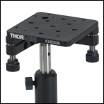
KM200B Mounted on Ø1/2" Post Using an 8-32 Cap Screw
- Two 80 TPI Adjusters for ±3° or ±4° of Fine Tip and Tilt Control
- Platform Can Be Oriented Horizontally or Vertically
- Designed for Use with Clamping Arms (Sold Below)
- Removable Knobs Expose Adjuster Screws with Hex Socket
- #8 (M4) Through Holes in Back Plate of Mounts for Ø1/2" Post Mounting
- Fabricated from Black Anodized Aluminum
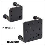
Thorlabs' KM100B(/M) and KM200B(/M) Kinematic Platform Mounts provide kinematic control for prisms and non-standard optics. Each contains several 6-32 (M4) tapped holes for mounting our PM3(/M) or PM4(/M) Clamping Arms (sold below). The KM200B(/M) additionally contains five 1/4"-20 (M6) tapped holes and four #8 (M4) counterbores that provide direct mechanical compatibility with standard optomechanics. The design used in the KM100B(/M) and KM200B(/M) offers an unobstructed path from any direction by positioning the knobs below the mounting plane, as shown in the photo to the right.
The KM100B(/M) is a 1.92" x 1.92" (48.6 mm x 48.6 mm) mount with ±4° of tip and tilt control, while the KM200B(/M) is a 2.90" x 2.90" (73.7 mm x 73.7 mm) mount with ±3° of tip and tilt control. An optional accessory, the LN2580 bronze locking nut, is available to lock the adjusters once the desired position is reached.
If desired, the mounting plate can also be removed and replaced with a user-supplied alternative, enabling custom mounting options. See the blue info icon (![]() ) in the table below for more information.
) in the table below for more information.

This animation shows how to convert between the right- and left-handed orientations on the KM100PM(/M). The procedure is identical for the KM200PM(/M). The KM05PM(/M) platform is not able to be removed, and the KM05PM(/M) platform does not need to be flipped over, since the platform is symmetrical.
Click to Enlarge
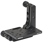
The KM200PM prism mount platform has 6-32 and 8-32 taps and #8 through holes.
- Adjusters Provide Fine Tip and Tilt Control
- MK05PM(/M): M2.5 x 0.20 Adjusters for ±5° Tip/Tilt
- KM05PM(/M): 100 TPI Adjusters for ±4° Tip/Tilt
- KM100PM(/M), and KM200PM(/M): 80 TPI Adjusters for ±4° Tip/Tilt
- Designed for Use with Clamping Arms (Sold Below)
- Through Holes or Taps in Back Plate of Mounts for Post Mounting
- Fabricated from Black Anodized Aluminum
Thorlabs' Kinematic Prism Mounts provide kinematic control for prisms, cube beamsplitters, corner cubes, and other optics that require tip and tilt control. The mounting platforms contain a variety of mounting options. The MK05PM(/M) and KM05PM(/M) feature 4-40 (M3) tapped holes for use with the MPM05(/M); the KM05PM(/M), KM100PM(/M), and KM200PM(/M) feature 6-32 (M4) tapped holes for the PM3(/M) and PM4(/M) Clamping Arms; the KM200PM also features 8-32 taps which can be used with the PM5 Stainless Steel Clamping Arm. All clamping arms are sold below.
The KM100PM(/M) and KM200PM(/M) also have a two-piece mounting platform assembly of can be configured in either a left- or right-handed orientation, as shown in the animation to the right. The assembly is secured to the front plate of each prism mount using two screws, see the table below for the screw type and required hex. See the mechanical drawings by clicking on the red Docs icon
(![]() ) below for details on each item's assembly. If desired, the mounting plate can also be removed and replaced with a user-supplied alternative, enabling custom mounting options. See the blue info icon (
) below for details on each item's assembly. If desired, the mounting plate can also be removed and replaced with a user-supplied alternative, enabling custom mounting options. See the blue info icon (![]() ) in the table below for more information.
) in the table below for more information.
The MK05PM(/M) features M2.5 x 0.20 adjusters that can be actuated using a 1.3 mm (0.05") ball driver or hex key. The HKTS-050 hex key adjuster knobs can also be used. The LN25M20 Lock Nut or F10SC1-5 Locking Collar may be used to lock the adjusters once the desired position is reached. The KM05PM(/M) features 3/16"-100 adjusters that can be actuated using a 5/64" (2.0 mm) ball driver or hex key. The HKTS-5/64 hex key adjuster knobs can also be used. The KM100PM(/M) and KM200PM(/M) both feature 1/4"-80 adjusters with removable knobs. The adjusters can also be actuated using a 5/64" (2.0 mm) ball driver or hex key. An optional accessory, the LN2580 bronze locking nut, is available to lock the adjusters of these two mounts once the desired position is reached.
The KM200PM(/M) platforms can also be used to mount any of our CMOS-Based Shack-Hartmann Wavefront Sensors. The KM200PM(/M) offers #8 (M4) through holes for WFS20 Series sensors, and 8-32 (M4) taps for WFS30 and WFS40 Series sensors. See the table below for details on the array of mounting holes on the platform of each prism mount.

This animation shows how to convert between the right- and left-handed orientations.
- Two 80 TPI Adjusters for ±4° of Fine Tip and Tilt Control
- Platform can be Removed and Secured to Either Arm Enabling Left- or Right-Handed Configuration
- Removable Knobs Expose Adjuster Screws with Hex Socket
- #8 (M4) Through Holes in Back Plate of Mounts for Ø1/2" Post Mounting
- Fabricated from Black Anodized Aluminum
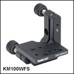
Thorlabs' KM100WFS Kinematic Platform Mount provides kinematic control for our WFS20 CMOS-Based Shack-Hartmann Wavefront Sensors. The mount features a similar design to our KM100PM (above) with a modified mounting platform designed to accommodate the WFS20 wavefront sensors using the two #8 through holes near the front edge of the plate and the included 8-32 screws. Please note that the optical axis of the sensor will not be centered over the optical post.
The two-piece mounting platform assembly can be configured in either a left- or right-handed orientation. The assembly is secured to the front plate using two 4-40 screws (3/32" hex). The two pieces of the mounting platform assembly are held together with two 3-48 screws (5/64" [2.0 mm] hex). This process mimics the one used to switch the handedness of the KM100PM, a video for which is shown above. If desired, the mounting plate can also be removed and replaced with a user-supplied alternative, enabling custom mounting options. See the blue info icon (![]() ) in the table below for more information.
) in the table below for more information.
The KM200PM(/M) Kinematic Prism Mount, available above, can also mount our WFS20 wavefront sensors. The mount platform contains two #8 through holes for High-Speed CMOS-Based Shack-Hartmann Wavefront Sensors, as well as an array of 6-32 (M4) tapped holes for other applications. The platform of the KM200PM(/M) is larger than that of the KM100WFS, yielding a less compact mounted assembly, but with more mounting options for optical components.

- Use for 1 mm Thick Plate or 5 mm Cube Optics
- ±3° Tip/Tilt Adjustment via Three M2.5 x 0.2 Precision Adjusters
- 360° Continuous Rotation with ±12° Fine Adjustment
- Fabricated from Stainless Steel
- Locking Collars Sold Separately
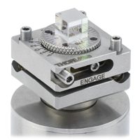
These kinematic rotation mounts are designed to mount either 5 mm cube optics, such as polarizing or non-polarizing beamsplitter cubes (Item # FBTB), or 1 mm thick plate optics up to 12.7 mm (0.5") wide, such as beamsplitters or mirrors (Item # FBTA) to our Ø1/2" Posts. Both versions require epoxy to mount optical components. The circular rotation plate can be rotated a full 360° and is engraved with a scale marked every 5°. Additionally, a Vernier scale provides 1° resolution for fine rotation.
An engraved dot is present on the FBTA(/M) Plate Optic Mount between the 0° and 90° engravings. Beamsplitter optics should be installed with the beamsplitter coating facing this dot. This allows an incident beam to be aligned so that it is split at the center of the mount.
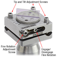
These mounts allow for tip, tilt, and rotational adjustment for precision beam alignment and steering control. Three vertical screws control the tip/tilt of the mount (see photo to the left), yielding up to ±3° of adjustment. Additionally, these screws can also provide some vertical adjustment when all three screws are rotated by the same amount. Care should be taken to avoid overextending the springs. When the screw above the 'Engage' engraving is tightened, the fine rotation adjustment screw (see photo to the left) gives up to ±12° adjustment with 1.7° per revolution. All adjustment screws use a 0.05" (1.3 mm) hex key, which is included with these mounts.
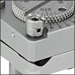
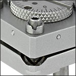
F10SC1-5 Locking Collars, available separately, can be used to lock an adjuster in a desired position. Simply insert the included hex key through the spanner wrench, and while holding the adjustment screw static, use the spanner wrench to tighten the locking nut (see video above). A hard stop can be created at any position by using two locking collars. Alternatively, a single collar can be epoxied to an adjuster using our G14250 epoxy to create a permanent hard stop.
Click to Enlarge
FBTB Cube Mount with 5 mm Beamsplitter Cube Mounted on a Ø1" Post with 1 mm Spacer
Click to Enlarge
Adjuster Locations on FBTA and FBTB Mounts (FBTA Plate Mount Shown with 12.7 mm x 1 mm Plate Beamsplitter Mounted on a Ø1/2" Post)
Each mount offers a bottom-located 8-32 (M4) tap for post mounting. When mounted on Ø1" Posts with 8-32 (M4) taps, the beam height can be increased using our Ø1" Post Spacers.
We also offer FiberBench-compatible versions of these mounts for mounting optics at the appropriate beam height within a FiberBench system.
Click to Enlarge
Two Collars Can be Locked Together to Create a Hard Stop
Click to Enlarge
A Single Locking Collar Can Lock an Adjuster in Position

Click to Enlarge
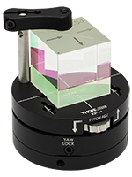
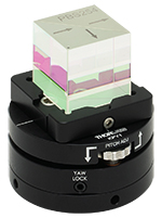
PBS254 Beamsplitter Secured to the KPY1 Pitch/Yaw Mount by a PM3 Clamping Arm
- Thumbwheel Provides ±3° Pitch Adjustment
- 360° Continuous Rotation with 5/64" (2.0 mm) Hex Locking Setscrew
- Ø2" Platform with 1" Height from Base of Mount
- Fabricated from Black Anodized Aluminum
Click to Enlarge
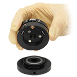
KPY1 Mount Separated into its Top and Bottom Components
The KPY1(/M) Kinematic Pitch/Yaw Mount is designed to provide pitch and yaw adjustment for optics or optomechanical components. The mount comprises a top section with pitch adjustment that can be rotated on top of a removable base plate; the two pieces are magnetically coupled. A 5/64" (2.0 mm) hex setscrew on the side of the mount allows the rotation to be locked, and the top and bottom sections each have a flat surface that can be used as a reference point for rotation adjustments. The ±3° of pitch adjustment is controlled by a thumbwheel in the mount's top plate.
The mount's top plate has two 6-32 (M4) threaded holes for use with PM3(/M) clamping arms and two 8-32 (M4) holes with 1" (50 mm) spacing. #8 (M4) and 1/4" (M6) holes through middle of the top and bottom of the mount, respectively, are accessible by separating the two sections. Lines to aid with alignment, including 1" and 1/2" squares, are engraved on the mount's top surface. Click on the blue icon in the table below for more details.
If desired, KPY1 mount can be used upside down, with the top plate secured to an optical table or post; however, note that the orientation of the pitch adjustment cannot be rotated if the top plate is used as the fixed portion of the mount.
Click to Enlarge
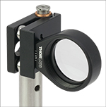
TPA01 Mounted Vertically on a Ø1/2" Post to Provide Yaw Adjustment
- Pitch Adapter Gives 1-Axis Adjustment for Fixed Mounts
- Compatible with All Fixed Mounts with Thickness Between 0.25" to 0.50" (6.4 mm to 12.7 mm)
- 1/4"-80 Adjuster Provides ±4° Pitch Adjustment
- Two 8-32 (M4) Tapped Holes Allow for Vertical and Horizontal Post Mounting
- Fabricated from Black Anodized Aluminum
The TPA01(/M) Pitch-Adjustable Kinematic Adapter holds fixed optic mounts (such as the fixed lens and fixed mirror mounts) with thicknesses between 0.25" to 0.50" (6.4 mm to 12.7 mm) that feature an 8-32 (M4) tap. A lip at the front of the adapter acts as a mechanical guide in order to square the mount to the adapter. The two-piece kinematic design allows the user to actuate one axis of a fixed optic holder, making it ideal for beam-leveling or optic centration applications.
A side-located (when horizontally mounted) 1/4"-80 fine pitch adjuster with a 5/64" (2 mm) hex (compatible with the HKTS-5/64 hex adjuster) is used to articulate the platform through its ±4° adjustment. The mount is equipped with a physical stop (F25SC1) on the pitch adjuster to prevent overextension of the mount. An 8-32 (M4) screw (included with the adapter) secures the fixed optic mount to the top platform through a counterbored slot in the underside of the adapter. The TPA01(/M) has 8-32 (M4) taps on the bottom and side of the adapter to permit horizontal and vertical mounting.

Click for Details
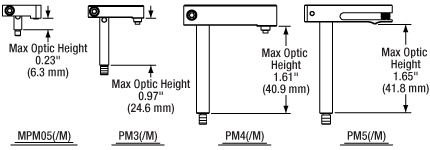
Figure 234A Mechanical Drawings
| Key Specifications | |||
|---|---|---|---|
| Item # | Max Optic Height | Clamping Distancea | Post Thread |
| MPM05(/M) | 0.23" (6.3 mm) | 0.37" (9.4 mm) | 4-40 (M3 x 0.5) |
| PM3(/M) | 0.97" (24.6 mm) | 0.69" (17.5 mm) | 6-32 (M4 x 0.7) |
| PM4(/M) | 1.61" (40.9 mm) | 1.16" (29.3 mm) | 6-32 (M4 x 0.7) |
| PM5(/M) | 1.65" (41.8 mm) | 0.90" (22.8 mm) | 8-32 (M4 x 0.7) |
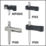
- Provide Clamping Force for Our Platform Mounts
- Threaded Hole on Top and Threaded Stud on Bottom of Post
- 4-40 Threads on MPM05
- 6-32 Threads on PM3 and PM4
- 8-32 Threads on PM5
- M3 x 0.5 Threads on MPM05/M
- M4 x 0.7 Threads on PM3/M, PM4/M, and PM5/M
- Maximum Optic Heights from 0.23" to 1.65" (6.3 mm to 41.8 mm)
- Extension Posts Available to Increase Max Optic Height
- PM3SP(/M) with PM3(/M): Hold Optics up to 2.21" (56.1 mm) Tall
- PM4SP(/M) with PM4(/M): Hold Optics up to 3.61" (91.7 mm) Tall
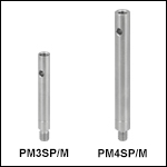
Click to Enlarge
Figure 234B Clamping Arm Extension Posts with Metric Indicator Groove
Thorlabs' Clamping Arms provide clamping force to secure optics to our kinematic platform mounts, stages, and V-clamps. The maximum optic height of the PM3(/M) or PM4(/M) clamping arms can be extended using our PM3SP(/M) or PM4SP(/M) extension posts, respectively. These extension posts are identical to the posts included in each complete clamping arm.
The MPM05 clamping arm can be mounted in 8-32 tapped holes by using the MSA8 thread adapter, which features internal 4-40 threads and external 8-32 threads and has an outer diameter of 0.40". The PM3 and PM4 clamping arms can be mounted in 8-32 tapped holes by using the AS6E8E thread adapter, which features internal 6-32 threads and external 8-32 threads. This thread adapter has an outer diameter of 0.24", which is the same as the PM4SP extension post and the post included with the PM4 clamping arm. This allows the clamping arm to be adjusted across the seam between either post and the adapter. The smaller diameters of the included post for the PM3 clamping arm and the PM3SP extension post cause the thread adapter to act as a stop for the clamping arm.
The PM5(/M) clamping arm is made entirely from heat-treated stainless steel, which helps maintain stability in fluctuating temperatures and provides vacuum compatibility. This clamping arm is recommended for use with the POLARIS-K1M4(/M), but it can be used with any platform mount or stage that has one or more 8-32 (M4 x 0.7) tapped holes. The PM5(/M) can hold optics up to 1.65" tall, and the distance from the post center to the contact point that holds the optic is 0.90".
Each clamping arm is attached to its post using a flexure mechanism that locks with a 5/64" (2.0 mm) balldriver or hex key. The setscrew on top of the clamping arm also accepts a 5/64" (2.0 mm) balldriver or hex key in order to clamp down on the optic. The post includes a through hole which can be leveraged for added torque when tightening down the post. Please see the diagram above for additional information.
 Products Home


 Zoom
Zoom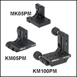
 Kinematic Platform Mounts