

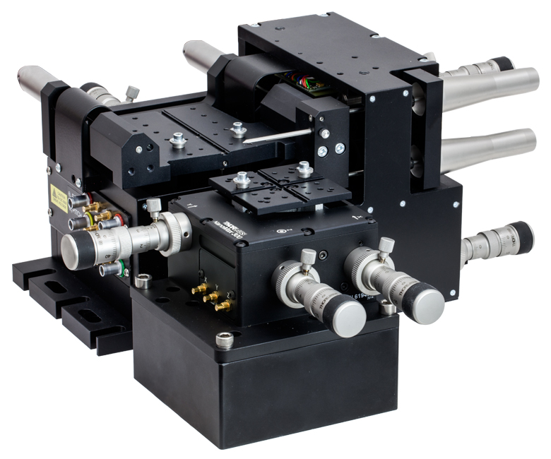
3-Axis NanoMax™ Flexure Stages
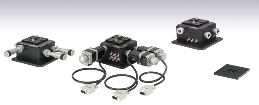
- 4 mm of Travel Per Axis
- Modular High-Resolution Drive Options
- Open- and Closed-Loop Piezo Versions
- Thermally Stable Design Minimizes Drift
MAX313D
Differential Micrometers
No Built-In Piezos
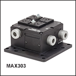
MAX302
No Actuators
Open-Loop Piezos
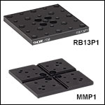
RB13P1
Additional Top Plate for
Off-Center and General
Optics Mounting
US Patents 6,186,016 and 6,467,762
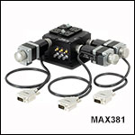
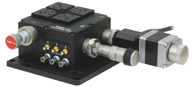
MAX381
Stepper Motor Actuators, Closed-Loop Piezo Operation
OVERVIEW
 Click to Enlarge
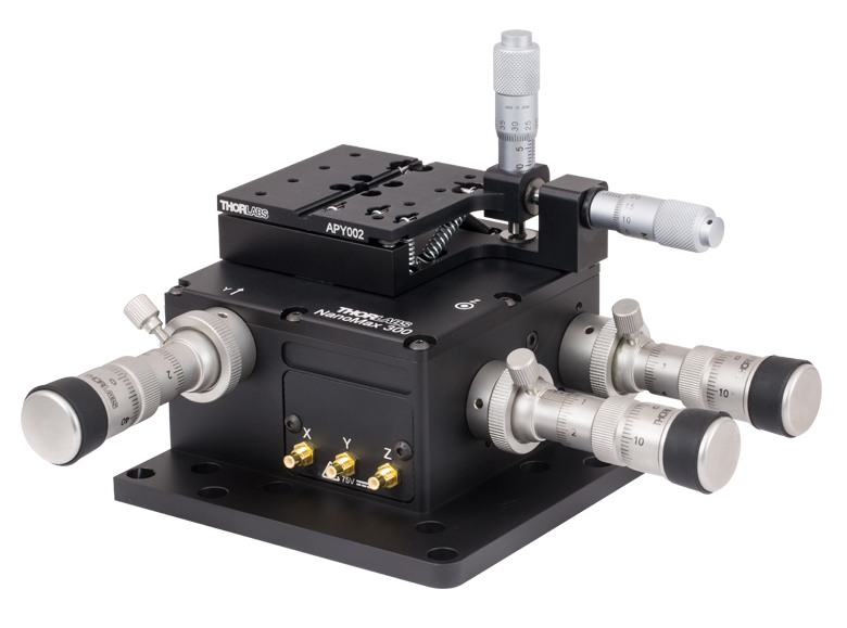
APY002 Pitch & Yaw Stage can be mounted on a 3-axis flexure stage in place of the regular top plate, enabling
 Click to Enlarge
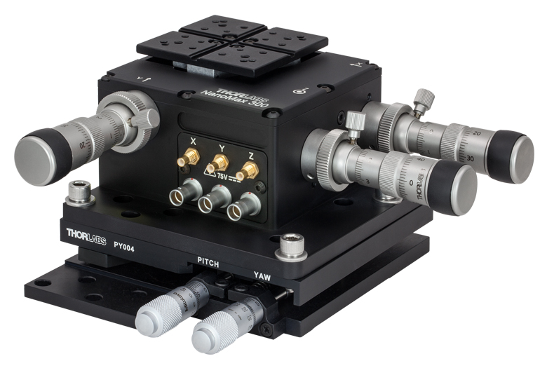
3-Axis Flexure Stage Mounted Directly to a PY004 High-Load Pitch and Yaw Stage for 5-Axis Control
| Common Specificationsa | ||
|---|---|---|
| Travel | 4.0 mm (0.16") | |
| Travel Mechanism | Parallel Flexure | |
| Deck Height (Nominal) | 62.5 mm (2.46") | |
| Optical Axis Height (Nominal) | 75 mm (2.95") | |
| Load Capacity (Max) | 1 kg (2.2 lbs) | |
| Thermal Stability | 1 µm/°C | |
| Parallelism of Top Plate | <100 µm | |
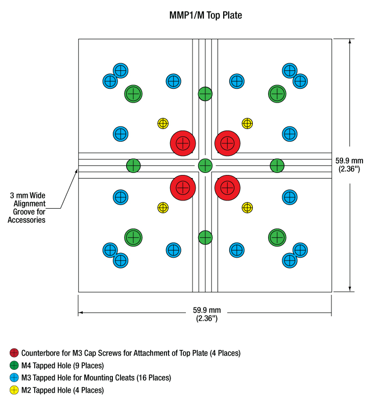
| Top Plate Mounting Holes |
Imperial Plate (Item # MMP1) |
 |
| Metric Plate (Item # MMP1/M) |
 |
|
Features
- 4 mm of X, Y, and Z Travel
- Flexure Design Ensures Smooth Continuous Motion and Long-Term Stability
- Grooved Top Plate Ensures Alignment of Multi-Axis Stage Accessories
- Compact Size Measuring 112.0 mm x 112.0 mm Without Drives
- All Adjusters Coupled to the Base to Minimize Crosstalk
- Modular Design for Interchanging Actuators
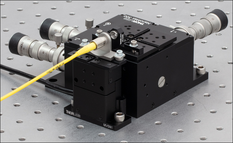
Thorlabs' 3-Axis NanoMax Flexure Stages are ideal for use in fiber launch systems or applications that require sub-micron repeatability. The parallel flexure design ensures precise, smooth, and continuous motions with negligible friction. Each unit provides 4 mm of X, Y , and Z travel with a maximum load capacity of 1 kg. The nominal deck height of the stage is 62.5 mm, which matches that of our 3-Axis MicroBlock compact flexure stages and RollerBlock long travel stages, as well as that of our MVSN1(/M) motorized vertical stage, allowing them to be used in conjunction (see below). Adapter plates are available for mounting our NanoMax stages to a wide range of other Thorlabs rotation and long travel linear stages.
 Click to Enlarge
HCS013 Objective Mount and HFF001 Quick-Release Fiber Clamp Accessories Attached to the Top Plate Using AM010 Cleats for Fiber Launch Applications
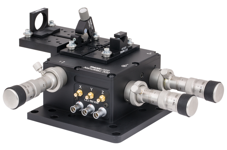
Precision Drives
Stages that are pre-configured with differential micrometer actuators or stepper motor actuators are offered below for out-of-the-box operation. The modular design of our 3-axis NanoMax stages allows the drives to be removed and replaced at any time. For compatible drive options, please see the Drives tab. The drives are coupled directly to the base to minimize any unwanted motion in the system. For nanopositioning applications, we have versions with internal piezoelectric actuators. See the PIC Testing Demo tab for an example application.
 Click to Enlarge
Piezo Options
These stages are available with or without integrated open- or closed-loop piezos. The piezoelectric actuators have 20 µm of travel and can be controlled using many of our open- or closed-loop piezo controllers (see the Specs tab for all compatible controllers). When these stages are coupled with a NanoTrak® controller (e.g. K-Cubes®, benchtop, or rack system module), the system becomes a powerful auto-alignment solution that maintains optical throughput and eliminates coupling efficiency loss due to thermal drift or other external forces. These piezo stages include three PAA100 Drive Cables and, in the case of closed-loop systems, three PAA622 Feedback Converter Cables.
Click to Enlarge
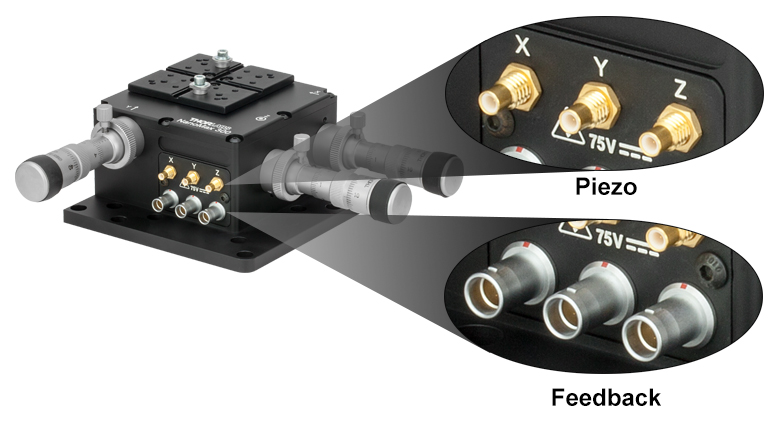
Piezo and Feedback Connections
Stages with closed-loop piezo actuators have internal strain gauge displacement sensors that provide a feedback voltage signal that is linearly proportional to the displacement of the piezoelectric element. This feedback signal can be used to compensate for the hysteresis, creep, and thermal drift that is inherent in all piezoelectric elements.
Please note that the piezo mechanism uses contact with the micrometer drives in order to move the top platform. If for any reason the stage is operated with the micrometer drives removed, blanking plugs must be fitted before the piezo actuators can function. To order blanking plugs, please contact Tech Support.
Easy Alignment of Accessories
Two central keyways in the top platform allow for rapid system reconfiguration while maintaining accessory alignment (see the image above and to the left). The crossed pattern allows for changing the orientation of the stage for right- and left-handed use. A wide range of accessories is available to mount items such as microscope objectives, collimation packages, wave guides, fiber, and much more. If options are required for off-center mounting of components, the grooved top plate can be replaced with the RB13P1 adapter plate (sold at the bottom of this page), which has an array of 1/4"-20 (M6) and 8-32 (M4) mounting holes.
| Multi-Axis Stage Accessories | |||||||||||
|---|---|---|---|---|---|---|---|---|---|---|---|
 |
 |
 |
 |
 |
 |
 |
 |
 |
 |
 |
 |
| Fiber Mounts |
Fiber Rotators |
Waveguide Mounts |
Diode Mounts |
Fixed Mounts |
Kinematic Mounts |
Top Plates |
Extension Platforms |
Fiber Chucks |
Slide Holders |
Kinematic Platforms |
Adapter Plates |
SPECS
Stage Specifications
| Item # | MAX313D(/M) | MAX312D(/M) | MAX311D(/M) | MAX383(/M) | MAX381(/M) | MAX303(/M) | MAX302(/M) | MAX301(/M) |
|---|---|---|---|---|---|---|---|---|
| Included Drives | DRV3 Differential Micrometer Drives | DRV208 Stepper Motor Drivesa | N/A | |||||
| Travelb | Manual (Coarse) and Motor: 4 mm Manual (Fine): 300 µm |
|||||||
| Deck Height (Nominal) | 62.5 mm (2.46") | |||||||
| Optical Axis Height (Nominal) |
75 mm (2.95") | |||||||
| Load Capacity (Max) | 1 kg (2.2 lbs) | |||||||
| Thermal Stability | 1 µm/°C | |||||||
| Parallelism of Top Plate | <100 µm | |||||||
| Piezo Specifications | ||||||||
| Control | N/A | Open Loop | Closed Loop | N/A | Closed Loop | N/A | Open Loop | Closed Loop |
| Drive Voltage Range | 0 - 75 V | 0 - 75 V | 0 - 75 V | |||||
| Travel | 20 µm +0.2 µm / -0.0 µm | 20 µm +0.2 µm / -0.0 µm | 20 µm +0.2 µm / -0.0 µm | |||||
| Resolutionc | ~10 nm | ~10 nm | ~10 nm | |||||
| Capacitance | 3.6 µF | 3.6 µF | 3.6 µF | |||||
| Bidirectional Repeatability | 0.2 µm | 0.05 µm | 0.05 µm | 0.2 µm | 0.05 µm | |||
| Absolute On-Axis Accuracy | 1.0 µm | 1.0 µm | 1.0 µm | |||||
| Resonant Frequency (No Load) |
375 Hz | 375 Hz | 375 Hz | |||||
| Resonant Frequency with 275 g (9.7oz) Load |
200 Hz | 200 Hz | 200 Hz | |||||
| Resonant Frequency with 575 g (20.3oz) Load |
150 Hz | 150 Hz | 150 Hz | |||||
| Included Piezo Cables | Three PAA100 | Three PAA100 Three PAA622 |
Three PAA100 Three PAA622 |
Three PAA100 | Three PAA100 Three PAA622 |
|||
| Compatible Piezo Controllers |
BPC303 MDT693B MPZ601 KPC101 KNA-VIS KNA-IR MNA601/IR BNT001/IR |
BPC303 MPZ601 KPC101 KNA-VIS KNA-IR MNA601/IR BNT001/IR |
BPC303 MPZ601 KPC101 KNA-VIS KNA-IR MNA601/IR BNT001/IR |
BPC303 MDT693B MPZ601 KPC101 KNA-VIS KNA-IR MNA601/IR BNT001/IR |
BPC303 MPZ601 KPC101 KNA-VIS KNA-IR MNA601/IR BNT001/IR |
|||
Differential Micrometer Specifications
| Item # | DRV3 |
|---|---|
| Travel Range | 8 mm (0.31") Coarse, 300 µm Fine |
| Coarse Adjustment | 500 µm/rev |
| Fine Adjustment | 50 µm/rev |
Arcuate Cross Talk Specifications
The measured maximum cross talk to the Z axis, when a movement is demanded in X or Y is <88 µm.
The table below shows the theoretical amount of cross talk to the Z axis, for movement at various X positions (Y axis at zero). Cross talk at Y axis positions (with X at zero) would be the same.
| X Axis Position (mm) | 0.0 | 0.5 | 1.0 | 1.5 | 2.0 | 2.5 | 3.0 | 3.5 | 4.0 |
| Arcuate Motion in Z Axis (µm) | 80.0 | 45.0 | 20.0 | 5.0 | 0.0 | 5.0 | 20.0 | 45.0 | 80.0 |
The measured maximum cross talk to the X and Y axes, when a movement is demanded in Z is <66 µm.
The table below shows the typical amount of cross talk to the X axis, for movement at various Z axis positions (Y axis at zero). Cross talk to Y axis positions (with X axis at zero) would be the same.
| Z Axis Position (mm) | 0.0 | 0.5 | 1.0 | 1.5 | 2.0 | 2.5 | 3.0 | 3.5 | 4.0 |
| Arcuate Motion in X Axis (µm) | 57.1 | 32.1 | 14.3 | 3.6 | 0.0 | 3.6 | 14.3 | 32.1 | 57.1 |
Stepper Motor Actuator Specifications
| Item # | DRV208 |
|---|---|
| Travel Range | 8 mm (0.31") |
| Bidirectional Repeatability | 5.0 µm |
| Maximum Force | 180 N |
| Maximum Velocity | 5 mm/s |
| Maximum Acceleration | 5 mm/s2 |
| Homing Repeatability | 13.5 µm |
| Recommended Controllers | BSC203, MST602 |
DRIVES

Click to Enlarge
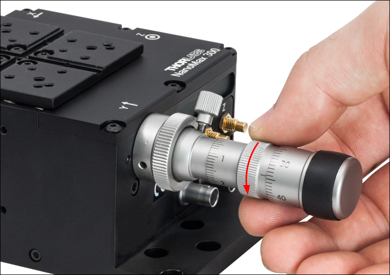
Step 1
Rotate the Actuator Counterclockwise to Disengage the Actuator from the Platform
Modular Drive Options
All 3-Axis NanoMax system have a modular design that allows the drives to be removed and replaced at any time. This allows for mix-and-match customization of actuators depending on the amount of automation or resolution needed on each axis.
Replacing a drive is simple and can be done in three steps. First, retract the leadscrew of the actuator until it is no longer engaging the moving body of the stage. Then unscrew the knurled knob attaching the existing drive to the stage. Finally, attach the new drive to the stage using the same knurled knob.
The drives compatible with our 3-axis NanoMax stages are summarized below. Some drives have limited travel range when used with the NanoMax 3-axis flexure stages; see the table for more details. For more detailed information on each drive, please see the full presentation for our Stepper Motor Drive, Differential Micrometers and Thumbscrew Drives, or In-line Piezo Actuators.
| Item # | DRV004 | DRV3 | DRV208 | DRV120 |
|---|---|---|---|---|
| Click Image to Enlarge |
 |
 |
 |
 |
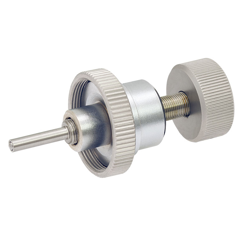
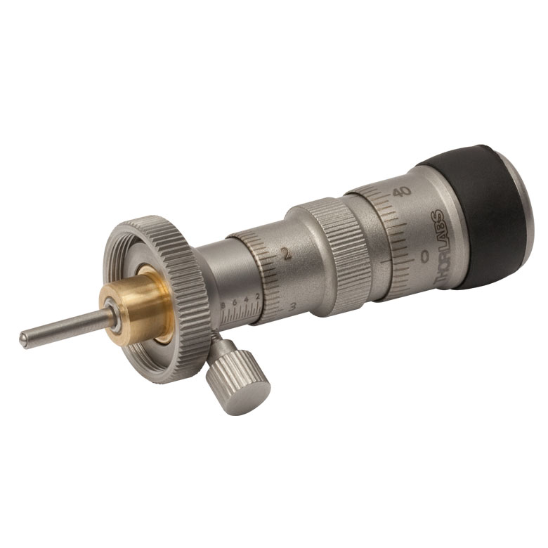
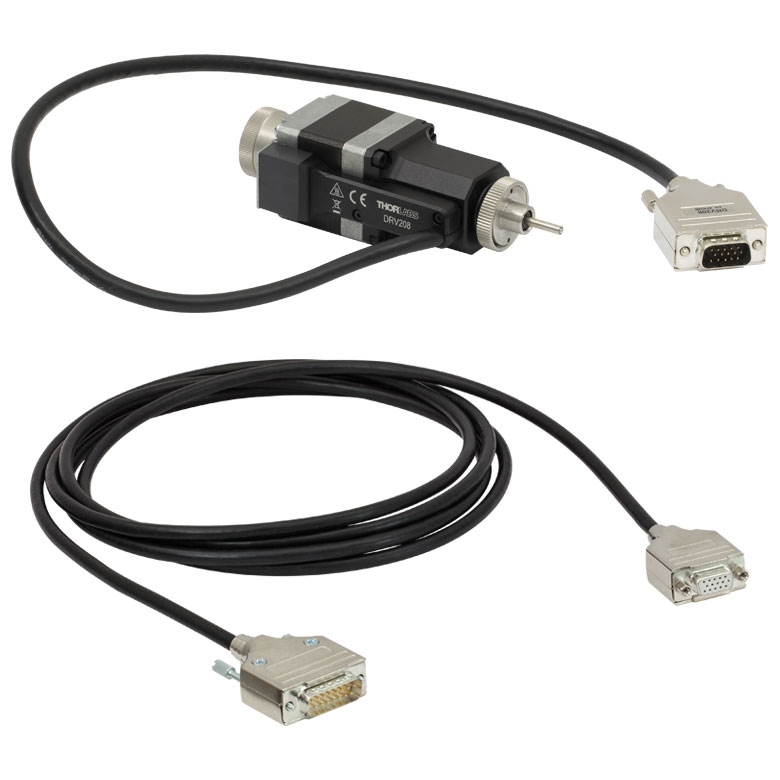
| Actuator Type | Thumbscrew | Differential Micrometera | Stepper Motorb | Piezoelectric with Feedback |
| Travel Range | 8 mm (0.31")c | Coarse: 8 mm (0.31")c Fine: 300 µm |
8 mm (0.31")c | 20 µm |
| Adjustment | 500 µm/revolution | Coarse: 500 µm/revolution Fine: 50 µm/revolution |
- | |
| Resolution | - | - | 200 steps/rev of Leadscrew | 5 nmd |
| Compatible Controllers | - | Benchtop: BSC200 Series Rack Module: MST602 |
Benchtop: BPC300 Series Rack Mount: MPZ601 K-Cubes®: KNA-VIS, KNA-IR, or KPC101 |
|
PIN DIAGRAMS
Displacement Sensor
7-Pin LEMO Male
MAX311D, MAX381, MAX301
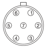
| Pin | Designation |
|---|---|
| 1 | +15 V |
| 2 | Oscillator + |
| 3 | 0 V |
| 4 | Signal Out - |
| 5 | Signal Out + |
| 6 | -15 V |
| 7 | Travel |
Piezo Drive Input
SMC Male
MAX311D, MAX312D, MAX381, MAX301, MAX302

Nominal Maximum Input Voltage: 75 V
DRV208 Stepper Motor Connector Pins
D-Type Male
MAX381, MAX383
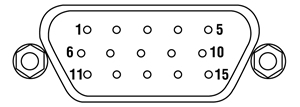
| Pin | Description | Pin | Description |
|---|---|---|---|
| 1 | Limit Switch 0 V | 9 | For Future Use |
| 2 | Limit Switch 0 V | 10 | +5 V |
| 3 | CW Limit Switch | 11 | - |
| 4 | Motor Phase B -ve | 12 | - |
| 5 | Motor Phase B +ve | 13 | +5 V |
| 6 | Motor Phase A -ve | 14 | - |
| 7 | Motor Phase A +ve | 15 | Ground |
| 8 | - | - | - |
INSIGHTS

Insights into Optical Fiber
Scroll down to read about:
- What factors affect the amount of light coupled into a single mode fiber?
- Is the max acceptance angle constant across the core of a multimode fiber?
Click here for more insights into lab practices and equipment.
What factors affect the amount of light coupled into a single mode fiber?
Click to Enlarge
Figure 193B Conditions which can reduce coupling efficiency into single mode fibers include anything that reduces the similarity of the incident beam to the optical properties of the fiber's guided mode.
Click to Enlarge
Figure 193A For maximum coupling efficiency into single mode fibers, the light should be an on-axis Gaussian beam with its waist located at the fiber's end face, and the waist diameter should equal the MFD.
Adjusting the incident beam's angle, position, and intensity profile can improve the coupling efficiency of light into a single mode optical fiber. Assuming the fiber's end face is planar and perpendicular to the fiber's long axis, coupling efficiency is optimized for beams meeting the following criteria (Figure 193A):
- Gaussian intensity profile.
- Normal incidence on the fiber's end face.
- Beam waist in the plane of the end face.
- Beam waist centered on the fiber's core.
- Diameter of the beam waist equal to the mode field diameter (MFD) of the fiber.
Deviations from these ideal coupling conditions are illustrated in Figure 193B.
These beam properties follow from wave optics analysis of a single mode fiber's guided mode (Kowalevicz).
The Light Source can Limit Coupling Efficiency
Lasers emitting only the lowest-order transverse mode provide beams with near-Gaussian profiles, which can be efficiently coupled into single mode fibers.
The coupling efficiency of light from multimode lasers or broadband light sources into the guided mode of a single mode fiber will be poor, even if the light is focused on the core region of the end face. Most of the light from these sources will leak out of the fiber.
The poor coupling efficiency is due to only a fraction of the light in these multimode sources matching the characteristics of the single mode fiber's guided mode. By spatially filtering the light from the source, the amount of light that may be coupled into the fiber's core can be estimated. At best, a single mode fiber will accept only the light in the Gaussian beam output by the filter.
The coupling efficiency of light from a multimode source into a fiber's core can be improved if a multimode fiber is used instead of a single mode fiber.
References
Kowalevicz A and Bucholtz F, "Beam Divergence from an SMF-28 Optical Fiber (NRL/MR/5650--06-8996)." Naval Research Laboratory, 2006.
Date of Last Edit: Jan. 17, 2020
Is the max acceptance angle constant across the core of a multimode fiber?
Click to Enlarge
Figure 193C Step-index multimode fibers have an index of refraction ( n ) that is constant across the core. Graded-index multimode fibers have an index that varies across the core. Typically the maximum index occurs at the center.

Click to Enlarge
Figure 193E Graded-index multimode fibers have acceptance angles that vary with radius ( ρ ), since the refractive index of the core varies with radius. The largest acceptance angles typically occur near the center, and the smallest, which approach 0°, occur near the boundary with the cladding
Click to Enlarge
Figure 193D Step-index multimode fibers accept light incident in the core at angles ≤|θmax | with good coupling efficiency. The maximum acceptance angle is constant across the core's radius ( ρ ). Air is assumed to surround the fiber.
It depends on the type of fiber. A step-index multimode fiber provides the same maximum acceptance angle at every position across the fiber's core. Graded-index multimode fibers, in contrast, accept rays with the largest range of incident angles only at the core's center. The maximum acceptance angle decreases with distance from the center and approaches 0° near the interface with the cladding.
Step-Index Multimode Fiber
The core of a step-index multimode fiber has a flat-top index profile, which is illustrated on the left side of Figure 193C. When light is coupled into the planar end face of the fiber, the maximum acceptance angle (θmax ) is the same at every location across the core (Figure 193D). This is due to the constant value of refractive index across the core, since the acceptance angle depends strongly on the index of the cladding.
Regardless of whether rays are incident near the center or edge of the core, step-index multimode fibers will accept cones of rays spanning angles ±θmax with respect to the fiber's axis.
Graded-Index Multimode Fibers
The core of a typical graded-index multimode fiber, shown on the right side of Figure 193C, has a refractive index that is greatest at the center of the core and decreases with radial distance ( ρ ). The equation included below the diagram in Figure 193E shows that the radial dependence of the core's refractive index results in a radial dependence of the maximum acceptance angle and numerical aperture (NA). This equation also assumes a planar end face, normal to the fiber's axis that is surrounded by air.
Cones of rays with angular ranges limited by the core's refractive index profile are illustrated Figure 193E. The cone of rays with the largest angular spread
Step-Index or Graded Index?
A step-index multimode fiber has the potential to collect more light than a graded-index multimode fiber. This is due to the NA being constant across the step-index core, while the NA decreases with radial distance across the graded-index core.
However, the graded-index profile causes all of the guided modes to have similar propagation velocities, which reduces the modal dispersion of the light beam as it travels in the fiber.
For applications that rely on coupling as much light as possible into the multimode fiber and are less sensitive to modal dispersion, a step-index multimode fiber may be the better choice. If the reverse is true, a graded-index multimode fiber should be considered.
References
Keiser G, "Section 2.6." Optical Fiber Communications. McGraw-Hill, 1991.
Date of Last Edit: Jan. 2, 2019
PIC TESTING DEMO
PIC Demo Testing Station
Thorlabs offers a variety of components that enable construction of a photonic integrated circuit (PIC) testing station, including imaging systems, fiber optics, precision piezos, and manual stages. This page presents a demo system that drives an on-chip laser and collects and analyzes the emitted light. The laser chip employed in this example PIC testing setup is a fully integrated, heterogeneous GaAs-on-SiN platform with an array of tunable lasers, with each source capable of coarsely covering the range from 765 to 795 nm. This PIC chip was supplied by Nexus Photonics. The scheme of this PIC testing demo can be generalized and customized to meet the needs of testing various PIC chips and is not restricted to the specific circuit used here. Click on the highlighted areas in Figure 787B or the links in Table 787A to find descriptions of the subsystems that comprise the demo testing station. Tables 787C and 787D provide a comprehensive list of all parts used in the demo.
| Table 787A PIC Demo Subsystems | |||||
|---|---|---|---|---|---|
| Imaging | Light Collection | PIC Control and Readout | PIC Chip Stage | Probe Card Positioning | General Setup |
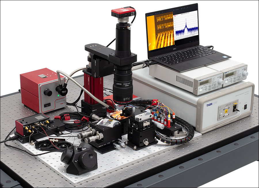
Figure 787B PIC Testing Demo Setup
| Table 787C PIC Demo Parts List | ||
|---|---|---|
| Item # | Qty. | Description |
| N/A | 1 | PIC Chip (Supplied by Nexus Photonics) |
| Imaging | ||
| SFM2a | 1 | Cerna® Mini Microscope |
| MCM301 | 1 | Three-Channel Stepper Motor Controller for Cerna Components |
| MCMK3 | 1 | 3-Knob USB HID Joystick |
| PLSXY | 1 | 2D Motorized Translation Stage for Rigid Stands |
| PLSZ | 1 | Motorized Module with 1" Travel, 95 mm Dovetail |
| LP126CU(/M) | 1 | Kiralux® Low-Profile 12.3 MP Color CMOS Camera |
| SM2CEFM | 1 | Adapter with External SM2 Threads and Female EF-Mounting Ring |
| CXY1A | 1 | XY Translating Lens Mount for Ø1" Optics |
| N/A | 1 | Canon Macro Lens |
| OSL2 | 1 | High-Intensity Fiber-Coupled Illuminator with Fiber Bundle |
| OSL2YFB | 1 | Gooseneck Y-Bundle for OSL2 and OSL2IR Fiber Light Sources |
| Light Collection | ||
| LFM1F-1 | 1 | FC/PC to Lensed Tip Fiber Patch Cable, Ø50 µm, 0.20 NA |
| TM50R2F1B | 1 | 1x2 Multimode Fiber Optic Coupler, Low OH, Ø50 µm Core, 0.22 NA, 90:10 Split, FC/PC |
| ADAFC3 | 2 | FC/APC to FC/APC Mating Sleeve |
| MAX311D(/M) | 1 | 3-Axis NanoMax™ Stage, Differential Drives, Closed-Loop Piezos |
| PY004(/M) | 1 | High-Load Pitch and Yaw Platform |
| KNA-VIS | 1 | K-Cube® NanoTrak® Active Auto-Alignment Controller, 320 - 1000 nm |
| KPC101 | 1 | K-Cube Piezo Controller and Strain Gauge Reader (Not Shown) |
| KCH301 | 1 | USB Controller Hub and Power Supply for Three K-Cubes or T-Cubes |
| Table 787D PIC Demo Parts List (Continued) | ||
|---|---|---|
| Item # | Qty. | Description |
| PIC Control and Readout | ||
| LDC202C | 2 | Benchtop LD Current Controller, ±200 mA HV |
| OSA202C | 1 | Fourier Transform Optical Spectrum Analyzer |
| PIC Chip Stage | ||
| MVS05(/M) | 1 | 1/2" Travel Vertical Translation Stage |
| N/A | 1 | Custom Machined Copper Mount for Chip Stage |
| Probe Card Positioning | ||
| XRV1(/M) | 1 | 14.0 mm Travel Vertical Translation Stage |
| LX20(/M) | 1 | Self-Contained XY 25 mm Translation Stage |
| N/A | 1 | Signatone Probe Card Holder |
| N/A | 1 | Custom Machined Probe Card Adapter |
| General Setup, Organization, and Cable Management | ||
| MB1824Ua | 1 | 18" x 24" Unanodized Aluminum Breadboard |
| CMS015 | 1 | Slit Harness Wrap, 5 m (16.5 ft) |
| BFCT | 1 | Passive Component Fiber Tray |
| CSV4 | 1 | Hook-and-Loop-Fastener Cable Straps with Lockdown Rivet (Qty. 5) |
| CS1 | 1 | Screw-On Cable Straps (Qty. 15) |
| B3648FXb | 1 | 36" x 48" Optical Breadboard |
| SDA90120 | 1 | ScienceDesk Frame for 36" x 48" (900 mm x 1200 mm) Tabletops |
Imaging

Click to Enlarge
Figure 787E Image of PIC chip, probes, and collection fiber acquired by the imaging system. The lensed fiber used for light collection can be seen in the lower left of the image. The scale bar shows 1 mm.
A widefield imaging systema is necessary to facilitate alignment of the probe card and light collection (lensed fiber) systems relative to the the PIC chip. Thorlabs' SFM2 Cerna® Mini Microscope provides a simple means to construct an imaging systemb. An LP126CU Kiralux® Scientific Camera attached to the SFM2 Mini Microscope displays the image of the PIC chip, probe card, and collection fiber (shown in Figure 787E). Illumination from a light source like the OSL2 High-Intensity Fiber-Coupled Illuminator can be guided to the chip via the OSL2YFB gooseneck fiber bundle. The combination of an MCM301 Stepper Motor Controller and an MCMK3 USB Joystick with the PLSXY and PLSZ Motorized Translation Stages enables three-dimensional motorized control of the imaging system.
- In this context widefield means an imaging field comparable to the size of the PIC chip.
- An EF-Mount Adapter Ring such as the SM2CEFM can be used to connect the camera lens to the Cerna microscope.


Click to Enlarge
Figure 787F PIC Chip Close Up Showing Probe Card, Collection Fiber, Illumination, and Imaging Microscope
Light Collection
Figure 787F shows a close up of the light collection geometry. Light emitted from the chip is collected by an LFM1F-1 Lensed Multimode Fiber and coupled into an optical spectrum analyzer (as discussed in the previous section). If multiple facets of analysis are desired, the signal can be split using a multimode fiber optic coupler such as the TM50R2F1B. To achieve adequate signal-to-noise ratio, fine positional control of the collection fiber is necessary. Thorlabs offers many components enabling precision control of fiber optics. Thorlabs' NanoMax™ line provides precision fiber positioning, and a PY004 base allows pitch and yaw control. The NanoMax MAX311D contains piezos, which can be controlled for auto-alignment with a combination of the KNA-VIS and KPC101 K-Cube® Controllers. The KCH301 and KCH601 K-Cube mounts are available as a USB hubs for the K-Cubes.


Click to Enlarge
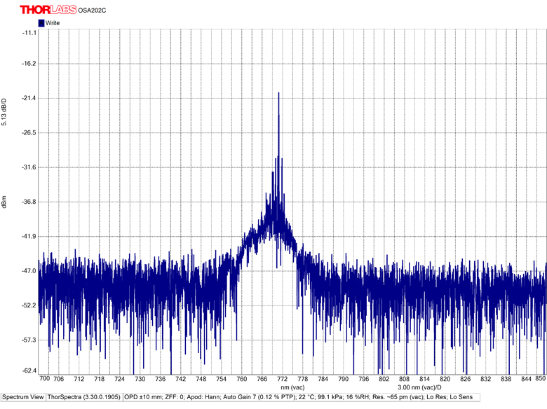
Figure 787G Screenshot of Spectrum Acquired with the OSA202C
PIC Control and Readout
In order to drive the laser circuit on the chip, current is supplied to the PIC chip via the probe card. Two LDC202C Laser Diode Drivers serve as the current sources here. Emitted light collected from the chip is directed into the fiber-coupled OSA202C Optical Spectrum Analyzer, which provides analysis and display of the signal. Figure 787G shows an example screenshot of the spectrum acquired by the OSA202C.
Depending on the particular PIC chip/testing application, various beam characterization and polarization measurement instruments can be used to construct a custom analysis setup to meet specific needs. Examples include the CCT10 Compact CMOS Spectrometer for spectroscopy, the PNA1 Intensity Noise Analyzer for high frequency-axis noise analysis, and the PAX1000IR1 Polarimeter for polarization measurements.
 |
 |
 |
 |
 |
| Laser Diode Drivers | Optical Spectrum Analyzers | Compact CMOS Spectrometers | Intensity Noise Analyzer | Polarimeters |
Positioning


PIC Chip Stage
Vertical (Z-axis) control of the PIC chip aids in focusing the widefield imaging system. A vertical drive stage such as the MVS05 Stage provides this additional degree of freedom. If more range is needed, the MVS1 Vertical Translation Stage allows up to 1" of travel.
Probe Card
The probe card serves to supply a multipoint electrical contact directly to the on-chip devices. To achieve optimal/flush contact with the chip multiple degrees of freedom are necessary. A vertical translation stage such as the XRV1 Stage provides vertical translation, and the LX20 Stage allows XY translation.
Thorlabs offers a wide selection of manual stages including linear translation, rotation, and multi-axis stages.
 |
 |
 |
 |
 |
| Optical Tables, Breadboards, and Supports | Solid Aluminum Breadboards | ScienceDesk Workstations | ScienceDesk Shelving | Cable Management |
General Setup, Organization, and Cable Management
Thorlabs offers a wide selection of general components and tools for construction, organization, and management of a PIC testing station. Optical tables, breadboards, and supports provide the foundation of any testing setup. ScienceDesk™ workstations can provide a convenient means to construct a vibration isolated table with a small footprint, and shelving affords convenient options for holding tools, equipment, and instruments. Cable management products for electric and fiber optic cables are also available.
Custom Capabilities
Both the lensed fiber holder and probe card holder were custom made for this specific PIC testing station demo application. Thorlabs offers a wide variety of custom solutions and manufacturing capabilities for various applications. Contact techsales@thorlabs.com for further information.
MULTI-AXIS STAGES
Multi-Axis Stage Selection Guide
Click to Enlarge
Figure 83A In the above application, a 3-Axis NanoMax flexure stage is aligned in front of a 6-axis stage at the proper 112.5 mm deck height using an AMA554 Height Adapter.
3-Axis Stages
Thorlabs offers three different 3-Axis Stage variations: NanoMax flexure stages, MicroBlock compact flexure stages, and RollerBlock long-travel stages. Each stage features a 62.5 mm nominal deck height. Our NanoMax line of 3-axis stages offers built-in closed- and open-loop piezos as well as modular drive options that include stepper motors, differential drives, or additional piezos. The MicroBlock stages are available with differential micrometer drives or fine thread thumbscrews; these drives are not removable. Finally, our RollerBlock stage drivers can be switched out for any actuator that has a Ø3/8" (9.5 mm) mounting barrel.
4- and 5-Axis Stages
Our 4- and 5-axis stages are ideal for the static positioning of waveguides or complex optical elements with respect to our 3-axis or 6-axis high-performance alignment stages. Thorlabs' 5-axis stages have nominal heights of 62.5 mm or 112.5 mm. The AMA554 Height Adapter can be used to raise the deck height of the 3-axis or 4-axis stages to 112.5 mm for compatibility with our 5-axis MicroBlock or 6-Axis NanoMax Stages.
6-Axis Stages
Thorlabs' 6-Axis NanoMax Nanopositioners are ideal for complex, multi-axis positioning and have a nominal deck height of 112.5 mm. These stages offer a common point of rotation and a patented parallel flexure design that allows all actuators to be coupled directly to the base to minimize any unwanted motion in the system. Built-in closed- and open-loop piezo options are available. A selection of modular drive options allows any axis to be manual or motorized with the option for external piezos. Our units without included actuators are also available in right- or left-handed configurations. To increase the stage height of the 3-axis stages to 112.5 mm, we recommend our AMA554 Height Adapter, shown in Figure 83A.
A complete selection and comparison of our multi-axis stages is available below.
3-Axis Stages
| Item # | MAX313D | MAX312D | MAX311D | MAX383 | MAX381 | MAX303 | MAX302 | MAX301 | MBT602 | MBT616D | RB13M | RBL13D | ||||||||
|---|---|---|---|---|---|---|---|---|---|---|---|---|---|---|---|---|---|---|---|---|
| Stage Type | NanoMax Flexure Stages | MicroBlock Compact Flexure Stages |
RollerBlock Long Travel Stages | |||||||||||||||||
| Included Drives | DRV3 Differential Micrometers | DRV208 Stepper Motor Actuators | N/A | Fine Thread Thumbscrews | Differential Micrometers | 148-801ST Micrometer Drives |
DRV304 Differential Micrometers |
|||||||||||||
| Built-in Piezos | N/A | Open Loop |
Closed Loop | N/A | Closed Loop | N/A | Open Loop | Closed Loop | N/A | N/A | ||||||||||
| Travel (X, Y, Z) | 4 mm (0.16") | 13 mm (0.51") | ||||||||||||||||||
| Deck Height (Nominal) | 62.5 mm (2.46") | |||||||||||||||||||
| Optical Axis Height (Nominal) | 75 mm (2.95") | |||||||||||||||||||
| Load Capacity (Max) | 1 kg (2.2 lbs) | 4.4 kg (9.7 lbs) | ||||||||||||||||||
| Thermal Stability | 1 µm/°C | - | ||||||||||||||||||
| Weight | 1.00 kg (2.20 lbs) | 0.64 kg (1.40 lbs) | 0.59 kg (1.30 lbs) | |||||||||||||||||
4-Axis Stages
| Item # | MBT401D MBT401D/M |
MBT402D MBT402D/M |
|
|---|---|---|---|
| Stage Type | 4-Axis Thin-Profile MicroBlock Device Stage | 4-Axis Low-Profile MicroBlock Device Stage | |
| Included Drives | Differential Micrometers | ||
| Built-in Piezos | N/A | ||
| Travel | Horizontal Axis (Y)a | 13 mm (0.51") | |
| Vertical Axis (Z) | 6 mm (0.24") | ||
| Pitch (θy) | ±5° | ||
| Yaw (θz) | ±5° | ||
| Deck Height (Nominal) | 62.5 mm (2.46") | ||
| Optical Axis Height (Nominal) | 75 mm (2.95") | ||
| Load Capacity (Max) | 0.5 kg (1.1 lbs) | ||
5-Axis Stages
| Item # | MBT401D (MBT401D/M) or MBT402D (MBT402D/M) with MBT501 |
PY005 | |
|---|---|---|---|
| Stage Type | 5-Axis MicroBlock Stage System | Compact 5-Axis Stage | |
| Included Drives | Differential Micrometers | 100 TPI Actuators | |
| Built-in Piezos | N/A | ||
| Travel | Optical Axis (X) | 13 mm (0.51") | 3 mm (0.12") |
| Horizontal Axis (Y) | 13 mm (0.51") | 3 mm (0.12") | |
| Vertical Axis (Z) | 6 mm (0.24") | 3 mm (0.12") | |
| Pitch (θy) | ±5° | ±3.5° | |
| Yaw (θz) | ±5° | ±5° | |
| Deck Height (Nominal) | 112.5 mm (4.43") | 62.5 mm (2.46")a | |
| Optical Axis Height (Nominal) | 125 mm (4.92") | 75 mm (2.95")a | |
| Load Capacity (Max) | 0.5 kg (1.1 lbs) | 0.23 kg (0.5 lbs) | |
6-Axis Stages
| Item # | MAX601D MAX601D/M |
MAX602D MAX602D/M |
MAX603D MAX603D/M |
MAX681 MAX681/M |
MAX682 MAX682/M |
MAX683 MAX683/M |
MAX607 MAX607/M MAX607La MAX607L/Ma |
MAX608 MAX608/M MAX608La MAX608L/Ma |
MAX609 MAX609/M MAX609La MAX609L/Ma |
|
|---|---|---|---|---|---|---|---|---|---|---|
| Stage Type | 6-Axis NanoMax Flexure Stage | |||||||||
| Included Drives | DRV3 Differential Micrometers | DRV208 Stepper Motor Actuators | N/A | |||||||
| Built-in Piezos | N/A | Open Loop | Closed Loop | N/A | Open Loop | Closed Loop | N/A | Open Loop | Closed Loop | |
| Travel | X, Y, Z | 4 mm (0.16") | ||||||||
| θx, θy, θz | 6° | |||||||||
| Deck Height (Nominal) | 112.5 mm (4.43") | |||||||||
| Optical Axis Height (Nominal) | 125 mm (4.92") | |||||||||
| Load Capacity (Max) | 1.0 kg (2.2 lbs) | |||||||||
3-Axis NanoMax Stage with Differential Adjusters
| Item # | MAX313D(/M) | MAX312D(/M) | MAX311D(/M) | |
|---|---|---|---|---|
| Manual Drive Specifications | ||||
| Item # | DRV3 | |||
| Travel | Coarsea | 4 mm (0.16") | ||
| Fine | 300 µm | |||
| Coarse Adjustment |
500 µm/rev | |||
| Fine Adjustment |
50 µm/rev | |||
| Piezo Specificationsb | ||||
| Control | N/A | Open Loop | Closed Loop | |
| Voltage Range | 0 - 75 V | |||
| Travel | 20 µm +0.2 µm / -0.0 µm | |||
| Resolutionc | ~10 nm | |||
| Bidirectional Repeatability | 200 nm | 50 nm | ||
| Absolute On-Axis Accuracy | 1.0 µm | |||
| Included Piezo Cables | Three PAA100 | Three PAA100 Three PAA622 |
||
- Preconfigured with DRV3 Differential Micrometers for Manual Adjustments
- Available With or Without Internal Closed- or Open-Loop Piezos
- Piezo Actuators Offer 20 µm of Travel
- Modular Design Allows Drives to be Removed and Replaced
- All Adjusters Tied to a Common Ground and Side Mounted
- Ideal for Use in Professional Fiber Launch Systems
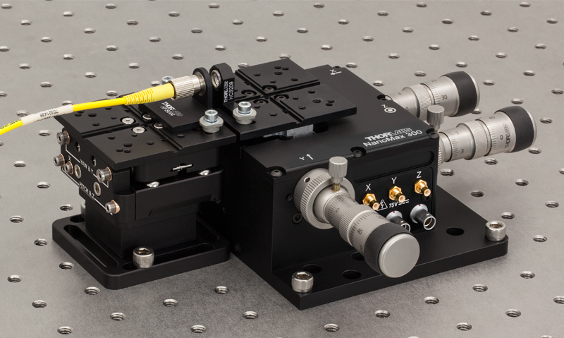
Thorlabs' NanoMax Stages with Differential Adjusters provide 4 mm of coarse travel and 300 µm of fine travel. The coarse adjuster has a scale with 10 µm graduations while the fine adjuster has a scale with 1 µm graduations. This resolution and travel range make these stages ideal for optimizing the coupling efficiency in a fiber alignment or waveguide positioning system. The graduations also allow for a clear reference point for absolute positioning within a system. The modular design of the included drives allows them to be replaced at any time; please see the Drives tab for more details and our full selection of compatible actuators.
Click to Enlarge
MAX311D 3-Axis Stage with a PY005/M 5-Axis Stage, PY005A2/M Base, and MMP1/M Top Plate for Fiber Coupling
In addition to the features above, the MAX312D and MAX311D NanoMax Stages incorporate open- and closed-loop piezoelectric actuators, respectively, with 20 µm of travel. The open-loop design does not contain an internal strain gauge sensor, while the inclusion of a strain gauge sensor in the closed-loop feedback design allows the MAX311D stages to compensate for the hysteresis, creep, and thermal drift that is inherent to all piezoelectric elements. These piezo stages include three PAA100 Drive Cables and, in the case of closed-loop systems, three PAA622 Feedback Converter Cables.
Imperial stages come with an MMP1 top plate and two AMA010 mounting cleats, while metric stages come with an MMP1/M top plate and two AMA010/M mounting cleats. These mounting plates contain a central keyway that allows for easy and repeatable alignment of all of the accessories listed in the overview. If off-center or breadboard mounting is necessary, we also offer the RB13P1 Top Plate.
Part Number | Description | Price | Availability |
|---|---|---|---|
MAX313D/M | 3-Axis NanoMax Stage, Differential Drives, No Piezos, Metric | $2,079.48 | Today |
MAX312D/M | 3-Axis NanoMax Stage, Differential Drives, Open-Loop Piezos, Metric | $2,730.28 | Lead Time |
MAX311D/M | 3-Axis NanoMax Stage, Differential Drives, Closed-Loop Piezos, Metric | $3,770.02 | Today |
MAX313D | 3-Axis NanoMax Stage, Differential Drives, No Piezos | $2,079.48 | Lead Time |
MAX312D | 3-Axis NanoMax Stage, Differential Drives, Open-Loop Piezos | $2,730.28 | Today |
MAX311D | 3-Axis NanoMax Stage, Differential Drives, Closed-Loop Piezos | $3,770.02 | Lead Time |
3-Axis NanoMax Stage with Stepper Motor Actuators
| Item # | MAX383(/M) | MAX381(/M) |
|---|---|---|
| Stepper Motor Drive Specificationsa | ||
| Item # | DRV208 | |
| Travelb | 4 mm (0.16") | |
| Bidirectional Repeatability | 5.0 µm | |
| Max Velocity | 5 mm/s | |
| Max Acceleration | 5 mm/s2 | |
| Included Motor Extension Cables |
Three PAA613 | |
| Recommended Motor Controllers | BSC203 and MST602 | |
| Piezo Specificationsa | ||
| Control | N/A | Closed Loop |
| Voltage Range | 0 - 75 V | |
| Travel | 20 µm +0.2 µm / -0.0 µm |
|
| Resolutionc | ~10 nm | |
| Bidirectional Repeatability | 50 nm | |
| Absolute On-Axis Accuracy | 1.0 µm | |
| Included Piezo Cables | Three PAA100 Three PAA622 |
|
- Preconfigured with DRV208 Stepper Motor Actuators for Automated Alignments
- Available With or Without Internal Closed-Loop Piezos
- Piezo Actuators Offer 20 µm of Travel
- Modular Design Allows Drives to be Removed and Replaced
- All Adjusters Tied to a Common Ground and Side Mounted
Thorlabs' NanoMax Stages with Stepper Motor Actuators provide 4 mm of travel along each axis. The actuators can achieve a bidirectional repeatability of 5.0 µm. Hall effect limit switches provide a high repeatability ideal for homing the motors. This is critical for auto-alignment applications that rely on a highly repeatable zero point. The high repeatability and small step size make these stages ideal for any high-precision automated fiber launch system or general application. The modular design of the included drives allows them to be replaced at any time; please see the Drives tab for more details and our full selection of compatible actuators. Each stage also includes three PAA613 3 m extension cables for the stepper motor actuators.
In addition to the features above, the MAX381 NanoMax Stage offers closed-loop piezoelectric actuators that have a 20 µm travel range. The closed-loop piezo actuators have strain gauge displacement sensors that provide a feedback signal which compensates for the hysteresis, creep, and thermal drift that is inherent to all piezoelectric elements. A 500 mm (19.7") drive cable is attached to each stepper motor actuator. The MAX381 stage also includes three PAA100 Piezo Drive Cables and three PAA622 Feedback Converter Cables.
Imperial stages come with an MMP1 top plate and two AMA010 mounting cleats, while metric stages come with an MMP1/M top plate and two AMA010/M mounting cleats. The mounting plates contain a central keyway that allows for easy and repeatable alignment of all of the accessories listed in the Overview tab. If off-center or breadboard mounting is necessary, we also offer the RB13P1 Top Plate.
Part Number | Description | Price | Availability |
|---|---|---|---|
MAX383/M | 3-Axis NanoMax Stage, Stepper Motor Drives, No Piezos, Metric | $3,158.62 | Today |
MAX381/M | 3-Axis NanoMax Stage, Stepper Motor Drives, Closed-Loop Piezos, Metric | $4,744.94 | Today |
MAX383 | 3-Axis NanoMax Stage, Stepper Motor Drives, No Piezos | $3,158.62 | Lead Time |
MAX381 | 3-Axis NanoMax Stage, Stepper Motor Drives, Closed-Loop Piezos | $4,744.94 | Today |
3-Axis NanoMax Stage
Click to Enlarge
MAX301 with a Stepper Motor, Thumbscrew, and Differential Actuator Attached to the X, Y, and Z Axis, Respectively
| Item # | MAX303(/M) | MAX302(/M) | MAX301(/M) |
|---|---|---|---|
| Internal Piezo Actuatorsa | |||
| Control | N/A | Open Loop | Closed Loop |
| Voltage Range | 0 - 75 V | ||
| Travel | 20 µm +0.2 µm / -0.0 µm | ||
| Resolutionb | ~10 nm | ||
| Bidirectional Repeatability | 200 nm | 50 nm | |
| Absolute On-Axis Accuracy | 1.0 µm | ||
| Included Piezo Cables | Three PAA100 | Three PAA100 Three PAA622 |
|
- No Preinstalled Actuators
- Available With or Without Internal Closed- or Open-Loop Piezos
- Piezo Actuators Offer 20 µm of Travel
- Modular Design Allows for a Variety of Drive Options (See Drives Tab for Details)
- All Adjusters Tied to a Common Ground and Side Mounted
Thorlabs' NanoMax Stages Without Included Actuators are ideal for customizing the type of drive that will be installed on each axis. This allows each axis to be configured depending on the precision or automation needed. Whether the application is a multimode fiber launch system using thumbscrews or an automated alignment setup using stepper motor actuators, each axis can be configured to meet the demand. For a list of all compatible actuators, please see the Drives tab.
In addition to the features above, the MAX302 and MAX301 NanoMax Stages offer open- and closed-loop piezoelectric actuators, respectively, with 20 µm of travel. The open-loop design does not contain an internal strain gauge sensor, while the inclusion of a strain gauge sensor in the closed-loop feedback design allows the MAX301 stages to compensate for the hysteresis, creep, and thermal drift that is inherent to all piezoelectric elements. These piezo stages include three PAA100 Drive Cables and, in the case of closed-loop systems, three PAA622 Feedback Converter Cables.
Imperial stages come with an MMP1 top plate and two AMA010 mounting cleats, while metric stages come with an MMP1/M top plate and two AMA010/M mounting cleats. These mounting plates contain a central keyway that allows for easy and repeatable alignment of all of the accessories listed in the overview. If off-center or breadboard mounting is necessary, we also offer the RB13P1 Top Plate.
Part Number | Description | Price | Availability |
|---|---|---|---|
MAX303/M | 3-Axis NanoMax Stage, Actuators Not Included, Metric | $1,180.83 | Today |
MAX302/M | 3-Axis NanoMax Stage, Actuators Not Included, Open-Loop Piezos, Metric | $1,638.42 | Today |
MAX301/M | 3-Axis NanoMax Stage, Actuators Not Included, Closed-Loop Piezos, Metric | $2,795.10 | Today |
MAX303 | 3-Axis NanoMax Stage, Actuators Not Included | $1,180.83 | Today |
MAX302 | 3-Axis NanoMax Stage, Actuators Not Included, Open-Loop Piezos | $1,638.42 | Today |
MAX301 | 3-Axis NanoMax Stage, Actuators Not Included, Closed-Loop Piezos | $2,795.10 | Today |
Tapped Top Plates
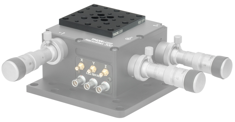
Click to Enlarge
Figure 361A RB13P1 Top Plate Shown Replacing the MMP1 Crossed Groove Mounting Plate on an MAX311D Flexure Stage
| Table 361B Mechanical Drawings | ||||
|---|---|---|---|---|
| Item # | RB13P1 | RB13P1/M | MMP1 | MMP1/M |
| Mechanical Drawing |
 |
 |
 |
 |
- RB13P1 Adapter Plate for General Purpose Accessories and Components
- Array of Thirteen 1/4"-20 (M6) and Twelve 8-32 (M4) Tapped Mounting Holes
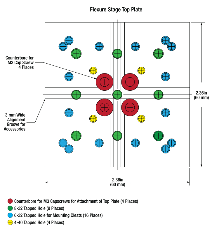
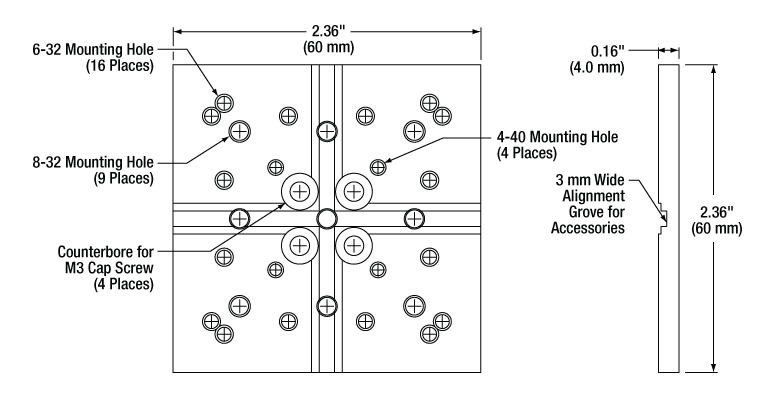
- MMP1 Standard 3-Axis Stage Top Plate (Included with All 3-Axis Stages)
- Two 3 mm Wide Central Keyways for Aligning Multi-Axis Stage Accessories
- Sixteen 6-32 (M3) Taps for Mounting Cleats
- Four 4-40 (M2) Taps
- Nine 8-32 (M4) Taps
The RB13P1(/M) Adapter Plate is designed as a replacement option for the standard MMP1(/M) grooved top plate sold with the stages above. Four counterbores that accept M3 screws allow it to be attached to the above stages. The 2.36" x 2.36" mounting surface is the same as the MMP1(/M) top plate that is included with the above stages. For complete details on the dimensions and tap locations of this top plate, please see the mechanical drawings in Table 361B.
The MMP1(/M) Top Plate is included with the stages sold above but can be purchased separately as well. This plate features two 3 mm wide central keyways in a crossed pattern to allow for rapid configuration while maintaining accessory alignment, making this plate ideal for fiber launch applications. This "crossed groove" design allows for the NanoMax stages to be used in a left- or right-handed configuration. The plate also contains an array of 4-40 (M2), 6-32 (M3), and 8-32 (M4) tapped mounting holes for securing and mounting various components. For complete details on the dimensions and tap locations of this plate, please see the mechanical drawings in Table 361B.
Part Number | Description | Price | Availability |
|---|---|---|---|
RB13P1/M | Adapter Plate with M6 and M4 Taps | $64.83 | Today |
MMP1/M | Replacement Mounting Plate for Flexure Stages with M4, M3, and M2 Taps | $74.76 | Today |
RB13P1 | Adapter Plate with 1/4"-20 and 8-32 Taps | $64.83 | Today |
MMP1 | Replacement Mounting Plate for Flexure Stages with 8-32, 6-32, and 4-40 Taps | $74.76 | Today |