 Products Home / Motion Control Electronics / Stepper Motor Controllers / APT Stepper Motor Control Module
APT Stepper Motor Control Module
- Two 50 W 2-Phase Bi-Polar Stepper Drive Outputs
- Motor Speeds up to 3000 RPM
- 409,600 Microsteps per Revolution of Motor
- Seamless Operation with Thorlabs and 3rd Party Motors/Stages
Full Suite of
Software Support
Tools Included
MST602


Please Wait
| APTTM Rack System Modules |
|---|
| 2-Channel Piezo Controller Module |
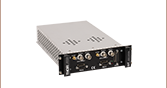
| 2-Channel Stepper Motor Controller Module |
| 2-Channel NanoTrak® Auto-Alignment Module |
| 2-Channel Brushless DC Motor Controller Module |
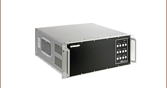
| USB Motion Control 19" Rack Chassis |
| All Thorlabs' Rack System Modules require the use of the APT™ MMR601 or MMR602 Rack System Enclosure. Independent operation of the modules outside the enclosure is not possible. |
Features
- Two Stepper Motor Drive Channels
- High Resolution Microstepping Control (For Very Fine Positioning Applications)
- Stable and Predictable Low-Speed Operation (For Velocity Sensitive Applications)
- Supports 2-Phase Bipolar Steppers up to 48 V / 50 W Peak
- Differential Encoder Feedback (QEP Inputs) for Closed-Loop Positioning
- USB Plug and Play for Multi-Axis Expansion
- Motor Control I/O Port (Jogging, Interlocks)
- Full Software Control Suite Included
- Intuitive Software Graphical Control Panels
- Extensive ActiveX® Programming Interfaces
- Fully Software Integrated with Other APT™ Family Controllers (Integrated Systems Development)
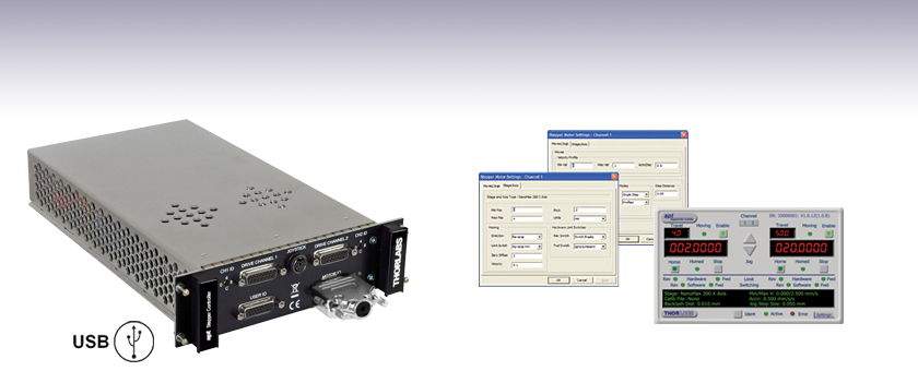
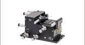
The APT™ MST602 module is a dual-channel, high-resolution, rack-mounted stepper motor driver designed for use with the APT MMR601 or MMR602 Motion Control 19" Modular Rack System. It has been designed to drive 2-phase bi-polar stepper motors up to 50 W, with or without encoder feedback, and is compatible with the full range of stepper-motor-equipped nanopositioning actuators and stages offered by Thorlabs. Alternatively, it is also compatible with any generic two-phase bi-polar motor of varying powers and varying cardinal step sizes.
This stepper motor controller has been designed specifically to operate with the highly flexible APT MMR601 or MMR602 Motion Control 19" Modular Rack System. Up to 6 MST602 stepper modules can be fitted to a given rack system, providing a scalable motion control solution for multi-axis motion control applications. For stand-alone controller options, please see the table below.
When used with a MMR601 or MMR602 Rack enclosure, this unit can be used with a PC via USB connection. Multiple modules can be connected to a single PC via standard USB hub technology for multi-axis motion control applications. Coupling this with the very user friendly APT software allows the user to get up and running very quickly. For example, all relevant operating parameters are set automatically for Thorlabs' stage/actuator products. Advanced custom motion control applications and sequences are also possible using the extensive ActiveX® programming environment, which is described in more detail on the Motion Control Software and APT Tutorials tabs.
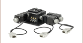
An optional 2-axis joystick console (item # MJC001) is also available for tactile, manual positioning of a stage. See the manual, found by clicking on the red Docs icon (![]() ), for more information on using the joystick console.
), for more information on using the joystick console.
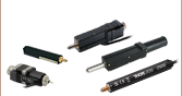
Cabling
Cables for connecting actuators or stages to the controller are shipped with the actuators or stages, not the controller. If you need help identifying the appropriate replacement cable, please contact Tech Support.
| Other Stepper Motor Controllers | ||
|---|---|---|
| K-Cube Single-Channel Controller | 1-, 2-, and 3-Channel Benchtop Controller | Modular 2-Channel Rack System Module |
Module Specifications
| Motor Drive Connector (15-Pin D-Type Female) Per Channel | |
|---|---|
| 2 Phase Bipolar Motor Drive Output | Forward, Reverse Limit Switch Inputs |
| Differential Quadrature Encoder (QEP) Input | Encoder 5 V (with Ground) |
| Motor Control Connector (15-Pin D-Type Female) | |
| Jog Forward/Back Input | TTL Level |
| Enable/Disable Interlock (per channel) | Connect to Return to Operate Motor |
| User 5 V (with Ground) 100 mA Max | |
| User I/O Connector (26-Pin D-Type Female) | |
| 4 Logic Inputs | TTL Level |
| 4 Logic Outputs | Open Collector |
| Trigger Input | TTL Level |
| Trigger Output | Open Collector |
| 2 Analogue Inputs | Single Ended 0-10 V (12-bit) |
| Motor Resolution | |
| 2048 Microsteps per Full Step | |
| For 200 Step Motor - 409,600 Microsteps/Rev | |
| For 24 Step Motor - 49,152 Microsteps/Rev | |
| Motor Drive Voltage | Up to 48 V |
| Motor Drive Power | Up to 50 Wpeak/25 Wave |
| Motor Speeds | Up to 3000 RPM (200 Full Step Motor) |
| Encoder Feedback Bandwidth | 500 kHz |
| General | |
| Housing | Single apt™ Rack System Bay |
| Dimensions (W x D x H) | 190 x 270 x 50 mm (7.5" x 10.6" x 2") |
| Weight | 1.5 kg (3.3 lbs) |
Compatible Motor Specifications
| Specification | Value |
|---|---|
| Peak Powers | 5 to 50 W |
| Average Power | 25 W Maximum |
| Step Angle Range | 20° to 1.8° |
| Coil Resistance (Nominal) | 4 to 15 Ω |
| Coil Inductance (Nominal) | 4 to 15 mH |
| Rated Phase Currents (Nominal) | 100 mA to 1 A |
Motor I/O Controller
D-type Female
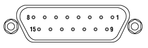
| Pin | Description | Return | Pin | Description | Return | Pin | Description | Return |
|---|---|---|---|---|---|---|---|---|
| 1 | User 5 V I/O | 9 | 6 | ** Channel 2 Emergency Stop Daisy Chain Link Return | 14 | 11 | * Channel 2 Jog Backwards | 9 |
| 2 | * Channel 1 Jog Forwards | 9 | 7 | ** Channel 2 Enable Return | 15 | 12 | ** Channel 1 Emergency Stop Daisy Chain Link | 4 |
| 3 | * Channel 2 Jog Forwards | 9 | 8 | Not Used | - | 13 | ** Channel 1 Enable | 5 |
| 4 | ** Channel 1 Emergency Stop Daisy Chain Link Return | 12 | 9 | User 0V | - | 14 | ** Channel 2 Emergency Stop Daisy Chain Link | 6 |
| 5 | ** Channel 1 Enable Return | 13 | 10 | * Channel 1 Jog Backwards | 9 | 15 | ** Channel 2 Enable | 7 |
Notes
* Jog inputs are opto-coupled and must be short circuit to User 0V (pin 9) in order to function.
** Channel enable inputs and daisy chain links are non-driveable and require a closed contact to the associated return pin in order to function.
User I/O Controller
D-type Female
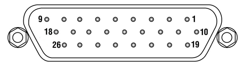
| Pin | Description | Return | Pin | Description | Return | Pin | Description | Return |
|---|---|---|---|---|---|---|---|---|
| 1 | Digital I/P 1 | 19 | 10 | Digital O/P 1 | 19 | 19 | ‡ Digital Ground 1 (0 V) | - |
| 2 | Digital I/P 2 | 19 | 11 | Digital O/P 2 | 19 | 20 | Ext Trigger I/P | 22 |
| 3 | Digital I/P 3 | 19 | 12 | Digital O/P 3 | 19 | 21 | Ext Trigger O/P | 22 |
| 4 | Digital I/P 4 | 19 | 13 | Digital O/P 4 | 19 | 22 | ‡ Digital Ground 2 (0 V) | - |
| 5 | Channel 1 RS232 TX | - | 14 | Channel 2 RS232 TX | - | 23 | 5 V User O/P (50 mA Max.) | - |
| 6 | Channel 1 RS232 RX | - | 15 | Channel 2 RS232 RX | - | 24 | Reserved for Future Use | - |
| 7 | Not Used | - | 16 | Reserved for Future Use | - | 25 | Reserved for Future Use | - |
| 8 | † Channel 2 Analog I/P (+) | 17 | 17 | † 0 V (Analog Rtn) | 8 | 26 | * ‡ Analog Ground (0 V) |
- |
| 9 | † Channel 1 Analog I/P (+) | 18 | 18 | † 0 V (Analog Rtn) | 9 |
Notes
* For use with analog inputs.
† 0 to 10 V d.c. between I/P +ve and I/P -ve (e.g. pins 8 and 17).
‡ Ground pins are common to the equipment ground.
Drive Channel Connector
D-type Female
| Pin | Description | Pin | Description | Pin | Description |
|---|---|---|---|---|---|
| 1 | Encoder A +ve | 6 | Not Used | 11 | 0 V User |
| 2 | Encoder A -ve | 7 | Phase B - | 12 | Reserved for Future Use |
| 3 | Encoder B +ve | 8 | Phase A - | 13 | Reserved for Future Use |
| 4 | Encoder B -ve | 9 | CW Limit Switch | 14 | Phase B + |
| 5 | 5 V User | 10 | CCW Limit Switch | 15 | Phase A + |
Handset
Mini DIN Female
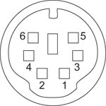
| Pin | Description | Pin | Description |
|---|---|---|---|
| 1 | RX (controller intput)/RS232 | 4 | Supply Voltage for Handset 5V |
| 2 | Ground | 5 | TX (controller output) |
| 3 | Ground | 6 | Ground |
Thorlabs offers two platforms to drive our wide range of motion controllers: our Kinesis® software package or the legacy APT™ (Advanced Positioning Technology) software package. Either package can be used to control devices in the Kinesis family, which covers a wide range of motion controllers ranging from small, low-powered, single-channel drivers (such as the K-Cubes™ and T-Cubes™) to high-power, multi-channel, modular 19" rack nanopositioning systems (the APT Rack System).
The Kinesis Software features .NET controls which can be used by 3rd party developers working in the latest C#, Visual Basic, LabVIEW™, or any .NET compatible languages to create custom applications. Low-level DLL libraries are included for applications not expected to use the .NET framework. A Central Sequence Manager supports integration and synchronization of all Thorlabs motion control hardware.

Kinesis GUI Screen
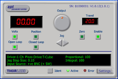
APT GUI Screen
Our legacy APT System Software platform offers ActiveX-based controls which can be used by 3rd party developers working on C#, Visual Basic, LabVIEW™, or any Active-X compatible languages to create custom applications and includes a simulator mode to assist in developing custom applications without requiring hardware.
By providing these common software platforms, Thorlabs has ensured that users can easily mix and match any of the Kinesis and APT controllers in a single application, while only having to learn a single set of software tools. In this way, it is perfectly feasible to combine any of the controllers from single-axis to multi-axis systems and control all from a single, PC-based unified software interface.
The software packages allow two methods of usage: graphical user interface (GUI) utilities for direct interaction with and control of the controllers 'out of the box', and a set of programming interfaces that allow custom-integrated positioning and alignment solutions to be easily programmed in the development language of choice.
A range of video tutorials is available to help explain our APT system software. These tutorials provide an overview of the software and the APT Config utility. Additionally, a tutorial video is available to explain how to select simulator mode within the software, which allows the user to experiment with the software without a controller connected. Please select the APT Tutorials tab above to view these videos.
Software
Kinesis Version 1.14.49
The Kinesis Software Package, which includes a GUI for control of Thorlabs' Kinesis and APT™ system controllers.
Also Available:
- Communications Protocol
Software
APT Version 3.21.6
The APT Software Package, which includes a GUI for control of Thorlabs' APT™ and Kinesis system controllers.
Also Available:
- Communications Protocol
The APT video tutorials available here fall into two main groups - one group covers using the supplied APT utilities and the second group covers programming the APT System using a selection of different programming environments.
Disclaimer: The videos below were originally produced in Adobe Flash. Following the discontinuation of Flash after 2020, these tutorials were re-recorded for future use. The Flash Player controls still appear in the bottom of each video, but they are not functional.
Every APT controller is supplied with the utilities APTUser and APTConfig. APTUser provides a quick and easy way of interacting with the APT control hardware using intuitive graphical control panels. APTConfig is an 'off-line' utility that allows various system wide settings to be made such as pre-selecting mechanical stage types and associating them with specific motion controllers.
APT User Utility
The first video below gives an overview of using the APTUser Utility. The OptoDriver single channel controller products can be operated via their front panel controls in the absence of a control PC. The stored settings relating to the operation of these front panel controls can be changed using the APTUser utility. The second video illustrates this process.
APT Config Utility
There are various APT system-wide settings that can be made using the APT Config utility, including setting up a simulated hardware configuration and associating mechanical stages with specific motor drive channels. The first video presents a brief overview of the APT Config application. More details on creating a simulated hardware configuration and making stage associations are present in the next two videos.
APT Programming
The APT Software System is implemented as a collection of ActiveX Controls. ActiveX Controls are language-independant software modules that provide both a graphical user interface and a programming interface. There is an ActiveX Control type for each type of hardware unit, e.g. a Motor ActiveX Control covers operation with any type of APT motor controller (DC or stepper). Many Windows software development environments and languages directly support ActiveX Controls, and, once such a Control is embedded into a custom application, all of the functionality it contains is immediately available to the application for automated operation. The videos below illustrate the basics of using the APT ActiveX Controls with LabVIEW, Visual Basic, and Visual C++. Note that many other languages support ActiveX including LabWindows CVI, C++ Builder, VB.NET, C#.NET, Office VBA, Matlab, HPVEE etc. Although these environments are not covered specifically by the tutorial videos, many of the ideas shown will still be relevant to using these other languages.
Visual Basic
Part 1 illustrates how to get an APT ActiveX Control running within Visual Basic, and Part 2 goes on to show how to program a custom positioning sequence.
LabVIEW
Full Active support is provided by LabVIEW and the series of tutorial videos below illustrate the basic building blocks in creating a custom APT motion control sequence. We start by showing how to call up the Thorlabs-supplied online help during software development. Part 2 illustrates how to create an APT ActiveX Control. ActiveX Controls provide both Methods (i.e. Functions) and Properties (i.e. Value Settings). Parts 3 and 4 show how to create and wire up both the methods and properties exposed by an ActiveX Control. Finally, in Part 5, we pull everything together and show a completed LabVIEW example program that demonstrates a custom move sequence.
Part 1: Accessing Online Help
Part 2: Creating an ActiveX Control
Part 3: Create an ActiveX Method
Part 4: Create an ActiveX Property
Part 5: How to Start an ActiveX Control
The following tutorial videos illustrate alternative ways of creating Method and Property nodes:
Create an ActiveX Method (Alternative)
Create an ActiveX Property (Alternative)
Visual C++
Part 1 illustrates how to get an APT ActiveX Control running within Visual C++, and Part 2 goes on to show how to program a custom positioning sequence.
MATLAB
For assistance when using MATLAB and ActiveX controls with the Thorlabs APT positioners, click here.
To further assist programmers, a guide to programming the APT software in LabVIEW is also available here.
| Posted Comments: | |
Daehan Choi
(posted 2023-04-06 17:15:59.613) Hi, We recently bought three 2-channel step motor driver module(MST602) and three 2-channel piezo driver module(MPZ601) to connect with NanoMax stage(MAX683/m).
We downloaded APT software to connect with our lab PC, but there are two problems.
1. When I'm trying to associate stage using APT config, channel setting is disabled. So I can't associate channel 2s with our NanoMax stage. (And in APT user, all the channel 2 shows "stage : unknown" message.)
2. Piezo controller modules are not shown on the Motor list. Is there no problem if I use piezo module without associating the stage?
I look forward to receiving your reply.
Best regards,
Daehan Choi JReeder
(posted 2023-04-11 05:13:22.0) Thanks for your enquiry. I am reaching out to you to discuss this with you further. For the MPZ601, there is no need to select the correct actuator using the APT config as the relevant parameters for a piezo can be set within the settings or are detected automatically by the software. José de-Oliva-Rubio
(posted 2023-03-15 08:20:57.717) Dear Sir or Madam,
We have on set of MAX601 with piezos and step actuators, They're so old (I don't remember exactly but they may date from 2009) that the controllers are CVI/Melles Griot.
Also we've recently purchased an additional pair of MAX601 with built-in piezos and step actuators for an additional measurement setup.
We control the platforms from Matlab using an in-house program to command the axis with a wireless game pad.
The problem is that according Mathworks they are going to discontinue the support of ActiveX controls in future versions of Matlab. Thus, being the correspondent functions (as for example actxcontrol) no longer available.
Would you kindly provide me the information needed to handle the platforms from Matlab with an alternative method? Because despite the anouncement from Mathworks (which was included in the 2019b release of Matlab) you still recommend the use of ActiveX controls to handle the platforms from Matlab.
Regards,
José do'neill
(posted 2023-03-16 01:21:40.0) Response from Daniel at Thorlabs: Thanks you for your feedback. Our Kinesis software has .NET based DLLs rather than the ActiveX DLLs that are included in the older APT software. I will reach out to you directly to discuss you particular application. leslie.bullock
(posted 2018-05-16 14:07:00.867) Doh! It might have assisted, if I had included my e-mail address for my previous post!
Kind Regards. - Les. user
(posted 2018-05-16 14:03:48.093) Hi.
I’m utilising LabVIEW to control the following items, 3 x MST602, installed into a MMR601, along with a MAX604/M 6-Axis stage.
Currently, I don’t have the physical hardware available, hence I’ve configured the Kinesis simulator with two BSC103 3 Channel Motor Controllers, these controllers in themselves are marked as ‘obsolete’, but they are the nearest I can find, in relation to the MST602 APT Stepper Motor Control Modules.
Anyway, moving on from this issue with the Kinesis simulator product selection, I can get the Kinesis User GUI software to satisfactory communicate with the Kinesis simulator.
However, when I configure LabVIEW to utilise the Kinesis software provided .dll to implement .NET control ‘calls’, I get a reported error of “No Suitable Devices Found”, consequently checking the Kinesis simulator, there isn’t any connection activity, which you do see, when the Kinesis User GUI software connects to the Kinesis simulator.
So I’ve found a similar issue on the NI forum (https://knowledge.ni.com/KnowledgeArticleDetails?id=kA00Z0000019RKySAM) , and have made the users suggested changes, but to no avail.
So my query is, as I’m wanting to use the Kinesis simulator, and not the actual hardware platform, do I have to invoke a connection to the simulator first, prior to attempting to establish a connection from “BenchtopStepperControl.NET”?
I note that there is a SimulationManager (within “Thorlabs.MotionControl.DeviceManagerCLI.dll”), but it doesn’t contain any public constructors, so it doesn’t appear that I can access the Kinesis simulator in that way.
So if you could kindly provide me with a detail explanation of the procedure, or an example of LabVIEW code that would facilitate the utilisation of the Kinesis simulator, I would be most grateful.
Thanks and Kind Regards. – Les. bhallewell
(posted 2018-05-18 05:13:00.0) Response from Ben at Thorlabs: Thank you for your feedback. I see you've also emailed us & I've got back to you with a solution on connecting to this hardware.
The methods for use of the Simulator can be found within the Kinesis .NET help file > DeviceManagerCLI.dll.
Within the Simulator, when selecting the BSC* series you can select Hardware Type revision which will enable you to simulate the latest hardware types. The Modular Stepper Controller is a Stepper Controller based on the Benchtop Stepper Motor (BSC103, BSC102, BSC101, BSC203, BSC202, BSC201) device used in the Modular Rack (MMR601). The Stepper Controller uses the Benchtop Stepper Motor (BSC103, BSC102, BSC101, BSC203, BSC202, BSC201) modules for it's functionality. gliang1
(posted 2015-03-31 16:20:55.753) Dear Sir/Madam,
Could you send me an older version of the APT software so that I can install it in my Windows XP system? Thanks!
Best regards,
Guozhen msoulby
(posted 2015-03-31 06:27:59.0) Response from Mike at Thorlabs: We stopped supporting windows XP for our APT software since 2013; all of our latest versions will only operate on windows 7 operating systems or later. However I have contacted you directly with details on how to download the very last version of APT that is compatible with Windows XP. user
(posted 2014-05-14 16:01:59.73) Are you only support Windows platforms? And than only via ActiveX? Please make a simple dll (.so) shared libary next time. msoulby
(posted 2014-05-14 11:08:42.0) Response from Mike at Thorlabs: Currently our APT package is only supported on windows based operating systems, back to windows XP. If you are using a non-windows platform then you will need to use our low level communications protocol over a virtual serial port to communicate with the controller, this document can be view at the following link http://www.thorlabs.de/software/apt/APT_Communications_Protocol_Rev_11.pdf We also have an APT.dll available which does not use ActiveX; if you can provide us with an email address we would be happy to send you this .dll and some details on its use. JCY
(posted 2014-02-04 13:49:37.17) Hello, do the auto alignment features of the MMR601/MNA601/R work equally well (at all?) with the MST602 stepper modules. I need the extra travel/flexibility of stepper motor/drives.
Thanks,
Jonathan msoulby
(posted 2014-02-05 04:29:12.0) Response from Mike at Thorlabs: The MNA601 can only provide piezo motion in response to the feedback signal. This signal can either be optical from the OPTICAL/PIN IN photodiode or an analogue electrical signal 0-10V input on the SIG IN connector. The MNA601 is only able to scan and track within the range of piezo travel provided by the stage you are driving. The stepper motors are there to provide coarse adjustments to get the stage close enough so that the piezo actuators can refine the alignment. If you need to use the stepper motors to initially find the signal then a dark search raster scan can be developed in a program such as LabView or Matlab to find the coarse position. Once this is position is found you can switch the program to the piezos and Nanotrak to optimise and maintain this alignment. tcohen
(posted 2012-07-12 13:25:00.0) Response from Tim at Thorlabs to Michal: Thank you for your inquiry. All of the Thorlabs Rack System Modules require the use of the MMR601 for operation. nejbauer
(posted 2012-07-12 12:20:58.0) Hello,
It is possible to operate MST601 unit without having MMR601 Rack system?
Best regards,
Michal Nejbauer jjurado
(posted 2011-05-27 10:27:00.0) Response from Javier at Thorlabs to i.abbadi: Thank you for your reply.It looks like you can use the SetAbsMovPos and MoveAbsolute commands. I was not able to contact you directly via e-mail regarding your last inquiry. Please contact us at techsupport@thorlabs.com so that we can discuss your application. i.abbadi
(posted 2011-05-27 05:43:14.0) hi , thanks for your response , well i want to command the rotation of two motors at the same time ;im looking for the instruction how to set its position without turning or make a boolean command to move the motors after setting there positions before , im using a BSC102 and the motors are connected to its channels jjurado
(posted 2011-05-26 10:12:00.0) Response from Javier at Thorlabs to i.abbadi: Thank you very much for contacting us. The LLSetGetDigOPs method sets or gets the status of the digital outputs on the APT unit associated with the ActiveX control instance. If the bSet parameter is set to TRUE, the method sets the output state. If bSet is set to FALSE, the method returns the output state. I will contact you with more details about this method and I will also like to get additional info about your application. You can also find more information in the Help section of the APT software: Start > All Programs > Thorlabs > APT > Help > APT Server Help > Programming Guide. i.abbadi
(posted 2011-05-26 06:54:14.0) hi,we have the MST601 and we could not control it by Labview. can we have more information about the LLSetGetDigOPs commands? Thorlabs
(posted 2010-10-20 16:15:29.0) Response from Javier at Thorlabs to jouko.viitanen: the User I/O connections of the MST601 are intended for use with ActiveX compatible platforms such as Visual Basic, LabVIEW, etc. You would use the low level commands LLSetGetDigOPs and LLSetGetHostDigOPs, which talk to the motherboard I/O instead of the separate card I/Os. I will contact you directly with more information about these commands. jouko.viitanen
(posted 2010-10-19 12:54:47.0) We have your MST601 stepper motor controller in the MMR rack. The controller works ok. I would also like to use the the 4 digital output bits available from the "User I/O" connector of the MST601. However, they are not available from the GUI panel, and I did not find any hints from the APT configurator utility, if some other driver needs to be installed in order to be able to switch the bits on/off in the APT user interface. |