 Products Home / Active Optical Devices / Optical Amplifiers / Benchtop, Fiber-Coupled Booster & Semiconductor Optical Amplifiers
Benchtop, Fiber-Coupled Booster & Semiconductor Optical Amplifiers
- Use as Signal Amplifiers or Optical Shutters
- Center Wavelengths from 1050 to 1625 nm
- Typical Small Signal Gain up to 30 dB
S9FC1137P
Polarization Maintaining
1030 to 1070 nm
S7FC1013S
Polarization Insensitive
1528 to 1562 nm


Please Wait
Key Specificationsa
| Item # | Amplifier Type |
Center Wavelength |
Optical 3 dB Bandwidth |
Saturation Output Power @ -3 dB |
Signal Gain @ Pin = -20 dBm |
Laser Class |
|---|---|---|---|---|---|---|
| S9FC1137P | BOA | 1050 nm | 50 nm | 9 dBm | 21 dB | 1M |
| S9FC1132P | BOA | 1300 nm | 87 nm | 15 dBm | 30 dB | |
| S7FC1013S | SOA | 1550 nm | 74 nm | 14 dBm | 13 dB | |
| S9FC1004P | BOA | 1550 nm | 100 nm | 15 dBm | 28 dB | |
| S9FC1080P | BOA | 1590 nm | 90 nm | 15 dBm | 25 dB | |
| S9FC1082P | BOA | 1625 nm | 80 nm | 13 dBm | 18 dB |
Features
- Center Wavelength: 1050, 1300, 1550, 1590, or 1625 nm
- Typical Noise: <0.5%
- Saturation Output Powers from 9 dBm to 15 dBm
- FC/APC Input and Output Connections
- Analog Modulation Input (0 to 5 V)
- Polarization Insensitive and Polarization Maintaining Versions
- TEC Temperature Stabilized to <0.01 °C
- USB Interface for Remote Operation
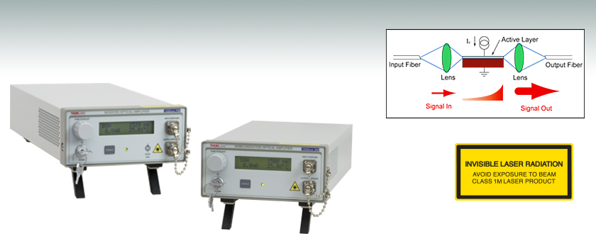
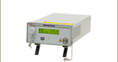
Thorlabs has integrated our fiber-coupled optical amplifiers into easy-to-use benchtop units. To use, simply connect fiber patch cables with FC/APC connectors to the input and output connectors and set the drive current and temperature with the dial on the front panel. The drive current can be modulated at up to 250 kHz using an input signal from 0 - 5 V (corresponding to zero transmission and maximum gain, respectively) via a BNC connector located on the rear panel of the unit. An internal microcontroller ensures that the amplifier is not overdriven from the modulation voltage. The unit's LCD displays the drive current and measured temperature of the amplifier, as well as the center wavelength of the unit and the amplifier type (SOA or BOA). The USB interface allows these amplifiers to be controlled remotely via a PC (see the manual for a list of commands for running the unit from a command line interface).
BOA vs. SOA
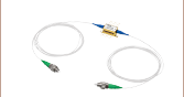
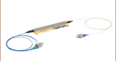
A booster optical amplifier (BOA) is a polarization sensitive device that only amplifies light with a specific polarization. Our BOAs are pigtailed with PM fiber and will amplify light aligned to the slow axis of the input fiber connector. Our benchtop BOAs are available with center wavelengths at 1050, 1300, 1550, 1590, and 1625 nm. For amplication at 1550 nm, we also offer a semiconductor optical amplifier (SOA) that provides polarization-insensitive amplification at a lower maximum gain than the BOA counterpart. For more information on amplifiers, see the Optical Amplifiers tab.
For butterfly packaged BOAs and SOAs, please see our 1050 nm, O-Band, E-Band, C-Band, and L-Band offerings.
| Table 2.1 Polarization Insensitive Semiconductor Optical Amplifiers (SOAs)a | |||
|---|---|---|---|
| Item # | S7FC1013S | ||
| Min | Typ | Max | |
| Wavelength (nm) | 1528 | 1550 | 1562 |
| Saturation Output Power at -3 dB (dBm) | 12 | 14 | - |
| Optical 3 dB Bandwidth (nm) | 70 | 74 | - |
| Signal Gain @ Pin = -20 dBm (dB) | 10 | 13 | - |
| RMS Gain Ripple (dB) | - | 0.1 | 0.5 |
| Noise Figure (dB) | - | 8 | 9.5 |
| Polarization Dependent Gain (dB) | - | 1.0 | 1.8 |
| Chip Length (mm) | - | 1.5 | - |
| Waveguide Refractive Index | - | 3.2 | - |
| Table 2.2 Polarization-Maintaining Booster Optical Amplifiers (BOAs)a | |||||||||||||||
|---|---|---|---|---|---|---|---|---|---|---|---|---|---|---|---|
| Item # | S9FC1137P | S9FC1132P | S9FC1004P | S9FC1080P | S9FC1082P | ||||||||||
| Min | Typ | Max | Min | Typ | Max | Min | Typ | Max | Min | Typ | Max | Min | Typ | Max | |
| Wavelength (nm) | 1030 | 1050 | 1070 | 1290 | 1300 | 1315 | 1530 | 1550 | 1570 | 1570 | 1590 | 1610 | 1600 | 1625 | 1650 |
| Saturation Output Power at -3 dB (dBm) | 6 | 9 | - | 15 | 17 | - | 13 | 15 | - | 12 | 15 | - | 10 | 13 | - |
| Optical 3 dB Bandwidth (nm) | 40 | 50 | - | 80 | 87 | - | 90 | 100 | - | 80 | 90 | - | 70 | 80 | - |
| Signal Gain @ Pin = -20 dBm (dB) | 17 | 21 | - | 27 | 30 | - | 25 | 28 | - | 20 | 25 | - | 14 | 18 | - |
| RMS Gain Ripple (dB) | - | - | 0.5 | - | 0.2 | 0.3 | - | 0.1 | 0.2 | - | 0.05 | 0.2 | - | 0.05 | 0.3 |
| Noise Figure (dB) | - | 11 | 14 | - | 7.0 | 9.0 | - | 7.0 | 9.0 | - | 7.0 | 9.0 | - | 7.0 | 9.0 |
| Chip Length (mm) | 1.5 | - | - | - | 1.5 | - | - | 1.5 | - | - | 1.5 | - | - | 1.5 | - |
| Waveguide Refractive Index | 3.3 | - | - | - | 3.2 | - | - | 3.2 | - | - | 3.2 | - | - | 3.2 | - |
| Table 2.3 Controller Specifications | |
|---|---|
| Performance Specifications | |
| Temperature Setpoint Resolution | ±0.01 °C |
| Temperature Control | TEC |
| Temperature Stability | <0.01 °C |
| Temperature Adjustment Range | 20.00 to 30.00 °C |
| Noise (RMS) | <0.5% Typical (Source Dependent) |
| Analog Modulation Input | 0 - 5 V (Zero Transmission to Maximum Gain) |
| Analog Modulation Bandwidth | 250 kHz for Full Depth of Modulation |
| Rise/Fall Time | 1.4 µsec / 1.6 µsec (For a Square-Wave Modulation Input) |
| Connections | |
| Fiber Ports | FC/APC (One Input and One Output) |
| Modulation Input Connector | BNC (Referenced to Chassis) |
| General | |
| AC Input | 100 - 240 VAC, 50 - 60 Hz |
| Dimensions (L x W x H) | 5.8" x 11.4" x 2.6" (147 x 290 x 66 mm) |
SOA Performance Plots
S7FC1013S: 1550 nm Center Wavelength
BOA Performance Plots
S9FC1137P: 1050 nm Center Wavelength
S9FC1132P: 1300 nm Center Wavelength
S9FC1004P: 1550 nm Center Wavelength
S9FC1080P: 1590 nm Center Wavelength
S9FC1082P: 1625 nm Center Wavelength
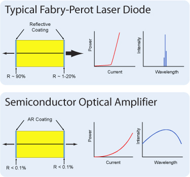
Semiconductor and Booster Optical Amplifiers (SOAs and BOAs) are similar in design to Fabry-Perot Laser Diodes, the difference being that Fabry-Perot laser diodes have reflective coatings on both end faces of the semiconductor chip (see the diagrams to the right). The optical feedback from the end faces establishes a cavity in which lasing can occur. SOAs and BOAs have an anti-reflection (AR) coating on both end faces of the semiconductor chip. The AR coatings limit the optical feedback into the chip so that lasing does not occur.
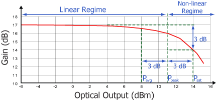
As is typical for all amplifiers, SOA/BOAs operate in two regimes: a linear, flat, constant gain regime and a non-linear, saturated output regime (see the plot below). When used to amplify a modulated signal, the linear regime is typically used to eliminate pattern-dependent distortion, multi-channel cross-talk and transient response issues common to EDFAs. The non-linear regime is used to take advantage of the highly non-linear attributes of the semiconductor gain medium (cross-gain modulation, cross phase modulation) to perform wavelength conversion, optical 3R regeneration, header recognition, and other high-speed optical signal processing functions.
For a CW input signal, the amount of power that can be produced by the amplifier is determined by the saturation output power (Psat) parameter. Psat is defined as the output power at which the small-signal gain has been compressed by 3 dB. The maximum amount of CW power that can be extracted is approximately 3 dB higher than the saturation power.
Modulation Input
BNC Female
0 to 5 V at up to 250 kHz
Computer Connection
USB Type B
USB Type A to Type B Cable Included
Interlock
2.5 mm Mono Phono Jack
Connector must be shorted in order for device to be in the "ON" state.
S7FC1013S Software
Version 1.2.0
Software package to operate Thorlabs' S7FC1013S Semiconductor Optical Amplifier, including a GUI, drivers, and LabVIEW/C++ SDK for secondary development.
| Posted Comments: | |
user
(posted 2024-05-03 07:56:47.69) Hi,
I have two questions about ASE.
1. I'm trying to work out the ASE power when there is no input light. Do you have a value for this ? it's the *1004P we are using.
2. I've seen the ASE spectrum, but it is in dB, why isn't it in dBm ?
Was it measured with an input signal at a specific power ?
Thanks ! cdolbashian
(posted 2024-05-10 03:27:46.0) Thank you for reaching out to us with this inquiry. I will answer each question directly. 1) The ASE power is dependent on the serialized unit you are using, and we ship the ASE LIV curve with each unit. In general the optical power of the ASE is about 2-3mW but will depend on the specific unit. 2) The graph is actually a dBm scale, although due to the spectrum-measurement technique which we have used, there is significant loss in intensity resulting in a relative scale rather than an absolute one. I have contacted you directly in order to help to walk through this data analysis/interpretation. Sungmoon Kim
(posted 2022-04-04 15:52:42.44) Hi! I'm considering the polarization-insensitive SOA device for sensing application. Could you please comment on the stability of the output polarization state? I would like to know how much the output polarization state will change over time. Many Thanks! ksosnowski
(posted 2022-04-13 05:42:44.0) Thanks for reaching out to us Sungmoon. While we do not specify an exact value for stability of the output polarization states, under appropriate drive conditions (stable current and stable temperature), the PDG will be quite stable for SOAs. There may be some slow drift/fluctuation in the beginning as the device comes to thermal equilibrium, but it should stabilize relatively quickly. I've reached out directly to discuss this application further. jian Hu
(posted 2021-09-30 15:32:40.623) Hi!
If my input light is modulated, what is the bandwidth of the modulating frequency? (S7FC1013S)
How to determine the current setpoint? cdolbashian
(posted 2021-10-28 04:04:52.0) Thank you for reaching out to us with this inquiry! This device has a max input bandwidth of ~100GHz. As far as current setpoint, we would always encourage you to start with a low current and increase it slowly to achieve the amplification which you desire. I have reached out to you directly to discuss this further. ZHANG Luan
(posted 2021-02-03 18:45:02.847) Hi,
Thanks a lot for reading this message.
We bought this SOA recently.
I wonder if is can be used bidirectionally.
Can I put the light into the output port and get the amplified light at the input port?
According to the datasheet, there are no isolators inside the SOA.
I should be most grateful if you would reply to me.
All my best,
Luan YLohia
(posted 2021-02-03 11:22:42.0) Hello Luan, thank you for contacting Thorlabs. The SOA is built with a symmetric structure so they can be used bidirectionally. If it is operated backwards, the gain will stay the same, but saturation power and noise figure will be different (if coupling efficiency of input and output fibers are different, which can be true in practice). Gong-Ru Lin
(posted 2020-01-08 21:02:16.883) Dear Sales Engineering,
Can you provide the same unit with SMF package?
Such as S9FC1132S (polarization independent).
Gong-Ru Lin asundararaj
(posted 2020-01-10 04:49:58.0) Thank you for contacting Thorlabs. While we may be able to offer a single mode fiber version of the S9FC1132P as a custom, an alternative would be to use the BOA1132S with the CLD1015. This is usually a preferred option since the polarization in the single mode fiber is sensitive to stresses, vibrations, and changes in temperature. In this case, the fiber itself is accessible when using the CLD1015 for any manipulation for polarization using the fiber polarization controllers. wtxqgg
(posted 2016-10-10 03:34:28.363) What will happen when it is used for a transform limited pulse@1310 nm. The width of the pulse is about 50fs. Will the pulse get wider or get chirped? jlow
(posted 2016-10-13 05:02:26.0) Response from Jeremy at Thorlabs: The SOA/BOA would not be able to amplify a short pulse like this without distorting the waveform. sears
(posted 2015-10-06 09:55:01.81) Can I specify a center wavelength at the short wavelength end (1530nm) given in the specs? I will be using this to amplify an ECDL and I want decent power (20mW +) out to 1500 nm if possible with seeding at 1 mW or so.
Thanks,
Trevor besembeson
(posted 2015-10-13 09:33:01.0) Response from Bweh at Thorlabs USA: I will follow-up regarding this special version. scw52
(posted 2015-07-27 17:41:40.163) Hi, we are using the S9FC1004P optical amplifier (OA) in a fibre-based Mach Zender interferometer, along with your fibres (P1-1550PM-FC-1) and phase modulators (LN65S-FC) to vary the path length.
I have found that feeding the OA output into the interferometer gives interference fringes, even if no input light source is used (i.e. when we are just amplifying noise); the coherence length of the light produced is about 0.1mm. What's more, if we connect a loose optical fibre to the OA input - still with no input light source - the signal is amplified by a factor 10, and the coherence length increases by a factor 10 (approx.). In both cases the maximum fringe contrast (Imax-Imin)/(Imax+Imin) is about 0.9, so these are very prominent fringes.
We are wondering if you know what is causing this effect (presumably the noise amplified has a temporal coherence determined by the amplifier medium's spontaneous decays), particulaly what is happening when we connect a loose fibre.
Please feel free to contact me directly to discuss/clarify this.
Many thanks,
Sid Wright besembeson
(posted 2015-08-21 03:03:37.0) Response from Bweh at Thorlabs USA: I will be contacting you by email. vishalsaxena
(posted 2015-03-13 10:34:10.34) Hi,
I am looking for an optical amplifier for our silicon photonics setup. We work with TE polarization type waveguides. I am trying to decide between polarization maintaining or polarization insensitive optical amplifiers.
Are there selective to one polarization? Do they change the polarization of the output light?
Thanks jlow
(posted 2015-03-24 03:45:54.0) Response from Jeremy at Thorlabs: The SOA series will amplify both polarization states whereas the BOA series will amplify only one polarization state. The advantage of the BOA series is the higher gain achievable. The selection of this will depend on your exact application and how you plan on using them. I will contact you directly to discuss about this further. mark.childers
(posted 2013-12-18 15:00:07.077) You list a possible center wavelength at 1500. I am trying to figure out if this product S7F1013S can amplify 1510, and what would be the saturation output power.
Could you tell me? jlow
(posted 2013-12-19 12:31:34.0) Response from Jeremy at Thorlabs: We guarantee at least 12dBm (14dBm typical) saturation output power for the SOA1013S (the SOA inside the S7FC1013S) over the full range of 1528-1562nm. The saturation output power will be lower at 1510nm; we estimate around 11dBm. The 1500nm number is the center of the ASE curve but the gain curve is typically shifted some to longer wavelengths. |