 Products Home / Active Optical Devices / Optical Amplifiers / L-Band Booster Optical Amplifiers (BOAs), 1590 - 1625 nm
L-Band Booster Optical Amplifiers (BOAs), 1590 - 1625 nm

- Polarization-Dependent Booster Optical Amplifiers
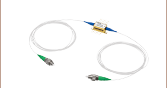
- SM or PM Fiber-Pigtailed Butterfly Package
- L-Band and Super L-Band BOAs Available
BOA1082P
FC/APC Connectors


Please Wait
| Optical Amplifier Selection Guide |
|---|
| 780 - 795 nm BOAs |
| 830 nm BOAs |
| 930 nm BOAs |
| 980 nm BOAs |
| 1050 nm BOAs |
| 1210 nm BOAs |
| 1250 nm BOAs |
| O-Band (1285 - 1350 nm) BOAs |
| E-Band (1410 nm) BOAs |
| C-Band (1550 nm) BOAs and SOAs |
| L-Band (1590 - 1625 nm) BOAs |
| 1685 nm BOAs |
| 1700 nm BOAs |
Click to Enlarge
When current is applied across the ridge waveguide, excited state electrons are stimulated by input light, leading to photon replication and signal gain.
Features
- L-Band and Super L-Band
- Polarization Maintaining: Amplifies Only One Polarization State
- Available with Either SM or PM Fiber Pigtails (1.5 m), 2.5 dB Loss at Each End of Chip
- FC/APC Connectors
- High Saturation Power, High Efficiency
- 3 dB Bandwidth: 80 nm or 90 nm (Typical)
- AR-Coated End Faces on Chip (R < 0.1%)
- Typical Applications: Boosting Laser Transmitters, Compensating for Transmit MUX/DeMUX Insertion Loss, Optical Shutter
Booster Optical Amplifiers (BOAs) are single-pass, traveling-wave amplifiers that perform well with both monochromatic and multi-wavelength signals. Since BOAs only amplify one state of polarization, they are best suited for applications where the input polarization of the light is known. For applications where the input polarization is unknown or fluctuates, a Semiconductor Optical Amplifier (SOA) is required. However, the gain, noise, bandwidth, and saturation power specifications of a BOA are superior to that of a SOA because of the design features that make the SOA polarization insensitive.
The BOA consists of a highly efficient InP/InGaAsP Multiple Quantum Well (MQW) layer structure. As seen in the schematic to the right, the input and output of the amplifier is coupled to the reliable ridge waveguide on the optical amplifier chip. Losses typically range from 1.5 to 2.5 dB for the fiber-to-chip and chip-to-fiber coupling (each). These coupling losses affect the total gain, noise figure (NF), and saturation power (Psat). While the gain produced by the amplifier exceeds that of the losses, these losses remain an important factor in determining the device's performance. For instance a 1 dB drop in input coupling efficiency increases the noise figure by 1 dB. Alternatively, a 1 dB drop in output coupling decreases the saturation power by 1 dB.
Click to Enlarge
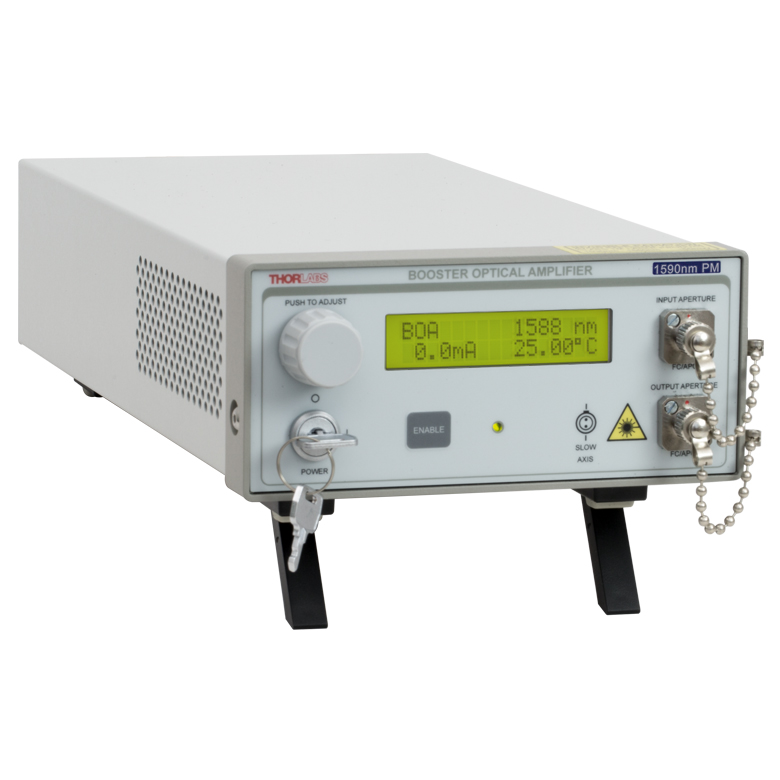
Our BOA1080P and BOA1082P optical amplifiers are also available in the S9FC1080P and S9FC1082P benchtop optical amplifiers, respectively.
The device is contained in a standard 14-pin butterfly package with either SMF or PMF pigtails that are terminated with FC/APC connectors. The connector key is aligned to the slow axis on all PMF pigtailed models. Optional polarization-maintaining isolators at the input, output, or both input/output are also available (specifications may vary with different configurations). Please contact Tech Support to order such a device.
Mount and Driver Options
These butterfly packages are compatible with the CLD1015 laser diode mount with integrated controller and TEC. When operating the BOAs on this page with the CLD1015, the orientation for type 1 pin configurations should be used. They are also compatible with the LM14TS and LM14S2 mounts, which can be used with our laser diode, TEC, and combined current/TEC controllers. When operating these lasers in environments with more than 5 °C variation in temperature, we recommend using the LM14TS mount, which provides active control of the butterfly package's case temperature to stabilize the amplifier's output wavelength and power.
Center Wavelength Note
The center wavelength (CWL) of the ASE spectrum in broadband semiconductor devices such as optical amplifiers may show variation between lots. Please refer to the Specs tab for the CWL tolerances of each particular model. For applications in which a specific ASE center wavelength is a critical concern, please contact Tech Support for information on the CWL of currently available lots.
| Item #a | Center Wavelength | 3 dB Bandwidth | Saturated Output Power (@ -3 dB) |
Small Signal Gain (@ Pin = -20 dBm) |
Noise Figure |
|---|---|---|---|---|---|
| BOA1080S and BOA1080P | 1590 nm Typical | 90 nm Typical | 15 dBm Typical | 26 dB Typical | 7.0 dB Typical |
| BOA1082S and BOA1082P | 1625 nm Typical | 80 nm Typical | 13 dBm Typical | 18 dB Typical | 8.5 dB Typical |
| Item # | Symbol | BOA1080S and BOA1080P | BOA1082S and BOA1082P | ||||
|---|---|---|---|---|---|---|---|
| Min | Typical | Max | Min | Typical | Max | ||
| Operating Current | IOP | - | 600 mA | 750 mA | - | 600 mA | 750 mA |
| Center Wavelength | λC | 1570 nm | 1590 nm | 1610 nm | 1600 nm | 1625 nm | 1650 nm |
| Optical 3 dB Bandwidth | BW | 80 nm | 90 nm | - | 70 nm | 80 nm | - |
| Saturation Output Powera (@ -3 dB) | PSAT | 12 dBm | 15 dBm | - | 10 dBm | 13 dBm | - |
| Small Signal Gain (@ Pin = -20 dBm, Typical λC) | G | 23 dB | 26 dB | - | 14 dB | 18 dB | - |
| Gain Ripple (RMS) @ IOP | δG | - | 0.05 dB | 0.2 dB | - | 0.05 dB | 0.3 dB |
| Noise Figure | NF | - | 7.0 dB | 9.0 dB | - | 8.5 dB | 9.5 dB |
| Forward Voltage | VF | - | 1.5 V | 2.0 V | - | 1.5 V | 2.0 V |
| Chip Length | - | - | 1.5 mm | - | - | 1.5 mm | - |
| Waveguide Refractive Index | - | - | 3.2 | - | - | 3.2 | - |
| TEC Operation (Typical/Max @ TCASE = 25/70 °C) | |||||||
| TEC Current | ITEC | - | 0.12 A | 1.5 A | - | 0.12 A | 1.5 A |
| TEC Voltage | VTEC | - | 0.25 V | 4.0 V | - | 0.25 V | 4.0 V |
| Thermistor Resistance | RTH | - | 10 kΩ | - | - | 10 kΩ | - |
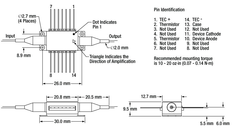
Mechanical Drawing and Pin Assignments
Note: All plots illustrate typical performance, and individual units may have slightly different performance, within the parameters outlined on the Specs tab.
BOA1080S and BOA1080P Graphs
The gain vs. output power plot and the amplified spontaneous emission (ASE) spectrum plot for the BOA1080S and BOA1080P were measured with an input wavelength of 1590 nm and an operating current of 600 mA.
BOA1082S and BOA1082P Graphs
The gain vs. output power plot and the amplified spontaneous emission (ASE) spectrum plot for the BOA1082S and BOA1082P were measured with in an input wavelength of 1620 nm and an operating current of 600 mA.
Booster optical amplifiers (BOAs) and semiconductor optical amplifiers (SOAs) are single-pass, traveling-wave amplifiers that perform well with both monochromatic and multi-wavelength signals. Since BOAs only amplify one state of polarization, they are best suited for applications where the input polarization of the light is known. For applications where the input polarization is unknown or fluctuates, a Semiconductor Optical Amplifier (SOA) is required. However, the gain, noise, bandwidth, and saturation power specifications of a BOA are superior to that of a SOA because of the design features that make the SOA polarization insensitive.
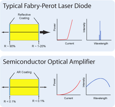
BOAs and SOAs are similar in design to Fabry-Perot Laser Diodes, the difference being that Fabry-Perot laser diodes have reflective coatings on both end faces of the semiconductor chip. The optical feedback from the reflective end faces establishes a cavity in which lasing can occur. SOAs and BOAs have an anti-reflection (AR) coating on both end faces of the semiconductor chip. The AR coatings limit the optical feedback into the chip so that lasing does not occur.
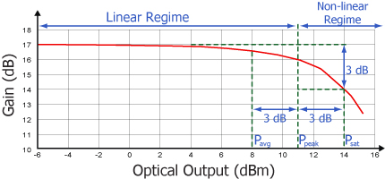
As is typical for all amplifiers, BOAs/SOAs operate in two regimes: a linear, flat, constant gain regime and a non-linear, saturated output regime. When used to amplify a modulated signal, the linear regime is typically used to eliminate pattern-dependent distortion, multi-channel cross-talk, and transient response issues common to EDFAs. The non-linear regime is used to take advantage of the highly non-linear attributes of the semiconductor gain medium (cross-gain modulation, cross phase modulation) to perform wavelength conversion, optical 3R regeneration, header recognition, and other high-speed optical signal processing functions.
For a continuous wave input signal, the amount of power that can be produced by the amplifier is determined by the saturation output power (Psat) parameter. Psat is defined as the output power at which the small-signal gain has been compressed by 3 dB. The maximum amount of CW power that can be extracted is approximately 3 dB higher than the saturation power.
| Posted Comments: | |
OHSOUNG KWON
(posted 2021-08-26 05:56:37.063) Dear Thorlabs,
Can I have detail drawing or 3d model of 'BOA1082P?'
I would like to design PCB artwork with cutting a space for BOA1082 on the PCB.
Regards,
OHSOUNG KWON YLohia
(posted 2021-08-27 03:10:37.0) Thank you for contacting Thorlabs. The specsheet of the BOA1082P contains a drawing and can be accessed here: https://www.thorlabs.com/_sd.cfm?fileName=19558-S01.pdf&partNumber=BOA1082P. Alternately, you may use the 3D model for the BOA930P (accessed here: https://www.thorlabs.com/_sd.cfm?fileName=QTN039466-E0W.sldprt&partNumber=BOA930P), since the BOA1082 and BOA930P share exactly the same butterfly packaging. OHSOUNG KWON
(posted 2021-08-26 04:01:42.733) Dear ThorLabs,
I am using 'BOA1082P.'
Is it possible to request for reducing optical cable, when I order?
I am looking forward to your reply.
Best regards,
OHSOUNG KWON YLohia
(posted 2021-08-27 03:10:36.0) Hello, custom BOAs can be requested by emailing techsales@thorlabs.com. We will discuss the possibility of offering this directly. OH SOUNG KWON
(posted 2021-02-25 11:15:17.947) Dear Thorlabs,
I'm using BOA1082P to amplifying power of laser diode.
Could you let me know about core diameter of optical fiber of BOA1082P?
Also, is it possible to change 9um core of optical fiber?
Or, is there a product to amplifying for TO-CAN type of laser diode?
Reguards,
OHSOUNG KWON YLohia
(posted 2021-02-25 10:18:59.0) Hello Ohsoung, the BOA1082P uses Corning's PM15-U40D fiber, which is specified for a mode field diameter of 10.5 um ± 0.5 um @ 1550 nm. I have reached out to you to discuss further directly. user
(posted 2018-03-29 15:49:21.37) Please advise the gain recovery time for BOA1080P. We are facing some pattern dependent distortions (output pulse amplitude and phase) for 5GHz rep rate input 1572nm laser pulse signals. However, this effect disappears at lower rep rates 5/2, 5/4GHz.
Thanks. YLohia
(posted 2018-04-12 08:38:42.0) Response from Yashasvi at Thorlabs USA: Hello, thank you for contacting Thorlabs. The recovery times have been measured to be around 300-500 ps for a similar devices (SOAs). Please note that distortions will be seen if you are operating in the saturated regime of the amplifier. To ensure that you are in the linear regime, you should operate with an output power no higher than the specified saturation power minus 6 dB. chunghsinyang
(posted 2016-04-11 12:49:42.283) Dear sir,
Can the wavelength be extend to be ~ 1700 nm for amplification?
Best regards
C.H. Yang besembeson
(posted 2016-04-13 08:54:43.0) Response from Bweh at Thorlabs USA: You would still have some amplification at 1700nm with the BOA1082P though it would be a few to several dB less compared to the peak wavelength as could be seen in the Amplified Spontaneous Emission plots that mimics the gain. To increase your gain at 1700nm (since we don't have one with ASE peak at that wavelength), we could hand select one that has an ASE peak close to 1650nm. I will contact you. kontrol2359
(posted 2015-04-24 06:52:13.323) I wanted to ask what would the extinction ratio of these booster amplifiers be at zero current (i.e. used as a switch)? I have got a low power frequency swept CW laser, obviously I could have a switch first and then send the pulse through the amplifier. However, it would be more economical if I could use the same device for both purposes. jlow
(posted 2015-04-28 04:11:58.0) Response from Jeremy at Thorlabs: We do not specify an extinction ratio (On/Off ratio at low seed power) since we do not explicitly test these for use as a switch. However, this should be in the 60dB - 70dB range based on the specs for BOA1004PXS. joao.ferreira
(posted 2015-03-26 07:30:52.68) Dear Madam or Sir
We are using BOA1080S optical amplifier and would appreciate some additional information.
1. Application note, if available.
2. The datasheets of BOA1080S and BOA1080P both describe the devices as "polarization-maintaining Booster Optical Amplifier". Since only the P model has PM fiber, what is the meaning of this statement? Is there a polarizing optical isolator inside the devices?
3. Is it possible to use BOA1080S as a bidirectional amplifier?
Looking forward to hear from you.
Best regards,
Joao Ferreira jlow
(posted 2015-03-26 03:01:28.0) Response from Jeremy at Thorlabs: We do not have an app. note for the BOA but we are available to answer your questions about our products. You can contact us directly at techsupport@thorlabs.com about this. The BOA amplifies one polarization state only whereas the SOA amplifies both polarization state. In a BOA, the TE polarization is amplified (or absorbed with no applied current) whereas the TM polarization pass through. The BOA1080S does have SM fiber on both input and output. We offer this because some users do want SM fiber on the unit (e.g. if one already uses a polarization controller in the setup). The BOA1080 is bidirectional since there's no internal isolator. However, we only test the BOA in the direction specified on the package so there might be a very slight performance difference in the reverse direction. On some of the BOA's we make, there's an internal isolator so those are not bidirectional. |