 Products Home / Optical Elements / Optical Lenses / Spherical Singlet Lenses / Plano-Convex Spherical Lenses / N-BK7 Plano-Convex Spherical Lenses / N-BK7 Plano-Convex Lenses (Uncoated)
N-BK7 Plano-Convex Lenses (Uncoated)
- Positive Focal Length and Near Best Form for Infinite Conjugate Applications
- Many Thorlabs Lenses Available in Zemax Catalog
LA1470
(Ø6 mm)
LA1576
(Ø9 mm)
LA1540
(Ø1/2")
LA1859
(Ø18 mm)
LA1229
(Ø1")
LA1417
(Ø2")
LA1238
(Ø75 mm)
LA1274
(Ø30 mm)
LA1252
(Ø25 mm)
LA1039
(Ø3 mm)
LA1024
(Ø2 mm)
LA1385
(Ø1.5")


Please Wait
| Table 1.1 Common Specifications | ||
|---|---|---|
| Diameters | 2 mm and 3 mm | 6 mm, 9 mm, 1/2", 18 mm, 25 mm, 1", 30 mm, 1.5", 2", and 75 mm |
| Lens Shape | Plano-Convex | |
| Substrate Material | N-BK7 (Grade A)a | |
| Wavelength Range | 350 nm - 2.0 μm (Uncoated) | |
| Design Wavelength | 587.6 nmb | |
| Index of Refraction | 1.515c | |
| Surface Flatness (Plano Side) | λ/2c | |
| Spherical Surface Powerd (Convex Side) |
3λ/2c | |
| Surface Irregularity (Peak to Valley) |
λ/4c | |
| Surface Quality | 60-40 Scratch-Dig | 40-20 Scratch-Dig |
| Thickness Tolerance | ±0.03 mm | ±0.1 mm |
| Diameter Tolerance | +0.00 / -0.02 mm | +0.0 / -0.1 mm |
| Centration | ≤5 arcmin | <3 arcmin |
| Abbe Number | vd = 64.17 | |
| Clear Aperture | >90% of Diametere | |
| Focal Length Tolerance | ±1% | |
 Zemax Files Zemax Files |
|---|
| Click on the red Document icon next to the item numbers below to access the Zemax file download. Our entire Zemax Catalog is also available. |

Features
- Material: N-BK7
- Wavelength Range: 350 nm - 2.0 μm (Uncoated)
- Available Uncoated (Below) or with One of Five Broadband Antireflection Coatings
- Focal Lengths Available from 4 to 2500 mm
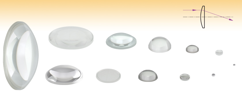
These uncoated Plano-Convex Lenses are fabricated from RoHS-compliant N-BK7 glass. N-BK7 is typically chosen whenever the additional benefits of UV fused silica (i.e., good transmission further into the UV and a lower coefficient of thermal expansion) are not necessary. They have a positive focal length and near-best-form shape for infinite and finite conjugate applications.
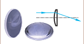
Plano-convex lenses can focus a collimated beam or collimate light from a point source. To minimize the introduction of spherical aberration, a collimated light source should be incident on the curved surface of the lens when being focused and a point light source should be incident on the planar surface when being collimated.
The focal length of each lens can be calculated using a simplified thick lens equation:
f = R /(n -1),
where n is the index of refraction and R is the radius of curvature of the lens surface. These lenses are fabricated from N-BK7, which has an Abbe Number of 64.17; this value is an indicator of the dispersion.
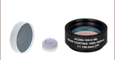
These N-BK7 Plano-Convex lenses are also available with one of five antireflection coatings (-A, -AB, -B, -C, or -D), which reduces the amount of light reflected from each surface of the lens (see Table 1.2 for links to each coating option). Since approximately 4% of the incident light is reflected at each surface of an uncoated substrate, the application of an AR coating improves transmission, which is important in low-light applications, and prevents the undesirable effects (e.g., ghost images) associated with multiple reflections. Having optics that are AR coated on both surfaces is particularly desirable for applications utilizing multiple optical elements. Please see the Graphs tab for coating information.
Thorlabs offers fixed lens mounts that can be used for mounting the lenses sold here. For mounting high-curvature lenses in select sizes, extra-thick retaining rings with SM05 (0.535"-40), SM1 (1.035"-40), or SM2 (2.035"-40) threading are available that provide extra clearance for spanner wrenches (see the Lens Mounting Guide tab for more information).
N-BK7 lens kits are also available. Please click here for information.
| Table 1.2 N-BK7 Plano-Convex Lens Selection Guide | |
|---|---|
| Unmounted Lenses | Mounted Lenses |
| Uncoated | Uncoated |
| -A Coating (350 - 700 nm) | -A Coating (350 - 700 nm) |
| -AB Coating (400 - 1100 nm) | -AB Coating (400 - 1100 nm) |
| -B Coating (650 - 1050 nm) | -B Coating (650 - 1050 nm) |
| -C Coating (1050 - 1700 nm) | -C Coating (1050 - 1700 nm) |
| -D Coating (1650 - 3000 nm) | - |
Custom Coatings are also available. Please contact Tech Sales for a quote.

| Quick Links to Other Spherical Singlets | ||||||
|---|---|---|---|---|---|---|
| Plano-Convex | Bi-Convex | Best Form | Plano-Concave | Bi-Concave | Positive Meniscus | Negative Meniscus |
Figure 2.1 shows the transmission curve for N-BK7, a RoHS-compliant form of BK7. Total Transmission is shown for a 10 mm thick, uncoated sample and includes surface reflections. Each of these unmounted N-BK7 plano-convex lenses can be ordered uncoated or with one of the following broadband AR coatings: 350 - 700 nm (designated with -A), 400 - 1100 nm (-AB), 650 - 1050 nm (-B), 1050 - 1700 nm (-C), or 1.65 - 3.0 µm (-D).
These high-performance multilayer AR coatings have an average reflectance of less than 0.5% (per surface) across the specified wavelength ranges (except for the -AB and -D coatings, which provide <1.0% average reflectance) and provide good performance for angles of incidence (AOI) between 0° and 30° (0.5 NA). The plot shown in Figure 2.2 indicates the performance of the standard coatings in this family as a function of wavelength. Broadband coatings have a typical absorption of 0.25%, which is not shown in the reflectance plots.
Click to Enlarge
Click Here for Raw Data
Figure 2.1 Above is the transmission curve for N-BK7, a RoHS-compliant
form of BK7. Total Transmission is shown for a 10 mm thick, uncoated sample
and includes surface reflections.
Figure 2.2 Thorlabs' Standard Broadband AR Coatings (8° AOI)
 Click to Enlarge
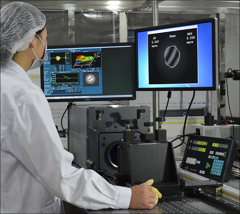
Figure 3.1 A Thorlabs technician measuring the irregularity of one of our singlets using a Zygo
Introduction
Thorlabs has a series of quality control procedures in order to ensure our singlets meet our standards and specifications. This starts with in-process inspections of the lens’ imaging capabilities and ends with a final inspection of surface quality and dimensions. Specifications for particular products can be found in their linked documentation by clicking the ![]() symbol. This tab will take you through the general process used to check for quality.
symbol. This tab will take you through the general process used to check for quality.
Singlet Quality Practices
In-process inspection begins once the singlet has been shaped to specifications. Focal length, surface irregularity, and surface power are checked, following sampling plan Level VI given in MIL-PRF-13830B (see below). These three specifications are imperative for proper imaging. Surface irregularity of parts is kept to below either a quarter wavelength or a half wavelength at 633 nm, depending on the material of the singlet. Table 3.3 is a graph of over 200 batches of singlets with irregularity data of both their front and back sides.
At this point, some uncoated singlets will proceed to final inspection, while others will receive an antireflective (AR) coating. The application of optical coatings has its own in-process inspections. To ensure the AR coating is applied properly, we verify both reflectance and transmission performance by scanning witness pieces using spectrophotometry; the material of these 2 mm thick witness samples matches the other parts in the run. For reflectance verification, we use at least one witness sample for each coating run. Transmitting optics receive two AR coatings, one on each surface, so for the verification of transmission, we use one witness sample that is also coated on both of its sides. Large runs use multiple witness samples to ensure the uniformity across the deposition chamber. By testing coating performance during every run, variance over time is kept low. To see how coatings vary, see Table 3.2.
Final inspection of both uncoated and AR-coated singlets includes a batch check of diameter and thickness and a 100% visual check to ensure that the surface quality, chamfer, and clear aperture meet our published specifications. While surface quality is cosmetic to a degree, scratches, digs, and other inclusions in the surface of a part can increase the chances of damage to the singlet when used with high-power sources. These inspections are done in a clean, dark room under lighting that meets the requirements of MIL-PRF-13830B. Inspection under a single light source in a dark room allows for inconsistencies in the glass to be located without being obscured by glare or reflections.
MIL-PRF-13830B: Performance Specifications for Optical Components
MIL-PRF-13830B is a document created by the U.S. Army Armament Research, Development and Engineering Center's Defense Quality and Standardization Office for the specifications covering how finished optical components should be manufactured, assembled, and inspected. While primarily for use in letting the military dictate how products they use can be incorporated into their equipment, these standards have been adopted by many optics manufacturers. To download a copy of the full document,
| Table 3.2 Coating Variance | Table 3.3 Singlet Irregularity |
||||
| -A Coating 350 nm to 700 nm |
-B Coating 650 nm to 1050 nm |
-C Coating 1050 nm to 1700 nm |
|||
| Transmission |  Click to Enlarge |
 Click to Enlarge |
 Click to Enlarge |
 Click to Enlarge |
|
| Reflectance |  Click to Enlarge |
 Click to Enlarge |
 Click to Enlarge |
||
Click here for raw data.
Figure 4.1 In the thick lens equation, use the index of refraction for N-BK7 at the wavelength of interest to approximate the wavelength-dependent focal length of any of the plano-convex lenses.
The focal length of a thick spherical lens can be calculated using the thick lens Equation 1. In this expression, nl is the index of refraction of the lens, R1 and R2 are the radii of curvature for surfaces 1 and 2, respectively, and d is the center thickness of the lens.

When using the thick lens equation to calculate the focal length of a plano-convex lens, R1=∞ and R2=-R. Note that the minus sign in front of R is due to the sign convention used when deriving the thick lens equations and values of R are reported in the Specs tab as well as on the mechanical drawing for each lens. Therefore, via substitution, the thick lens equation becomes Equation 2
The focal length of the lens calculated using the simplified thick lens equation directly above is the distance between the second (back) principle plane (H") and the position at which a collimated beam incident on the curved surface of the plano-convex is focused. The principle plane positions of a thick lens can be calculated with Equations 3 and 4:
 and
and 
However, as with the thick lens equation, H' simplifies to zero and H" simplifies to Equation 5
when used to calculate the principal plane locations of plano-convex lenses. fb is the back focal length of the lens, which is often referred to as the working distance of the lens.
| Recommended Mounting Options for Thorlabs Lenses | ||
|---|---|---|
| Item # | Mounts for Ø2 mm to Ø10 mm Optics | |
| Imperial | Metric | |
| (Various) | Fixed Lens Mounts and Mini-Series Fixed Lens Mounts for Small Optics, Ø5 mm to Ø10 mm | |
| (Various) | Small Optic Adapters for Use with Standard Fixed Lens Mounts, Ø2 mm to Ø10 mm | |
| Item # | Mounts for Ø1/2" (Ø12.7 mm) Optics | |
| Imperial | Metric | |
| LMR05 | LMR05/M | Fixed Lens Mount for Ø1/2" Optics |
| MLH05 | MLH05/M | Mini-Series Fixed Lens Mount for Ø1/2" Optics |
| LM05XY | LM05XY/M | Translating Lens Mount for Ø1/2" Optics |
| SCP05 | 16 mm Cage System, XY Translation Mount for Ø1/2" Optics | |
| (Various) | Ø1/2" Lens Tubes, Optional SM05RRC Retaining Ring for High-Curvature Lenses (See Below) |
|
| Item # | Mounts for Ø1" (Ø25.4 mm) Optics | |
| Imperial | Metric | |
| LMR1 | LMR1/M | Fixed Lens Mount for Ø1" Optics |
| LM1XY | LM1XY/M | Translating Lens Mount for Ø1" Optics |
| ST1XY-S | ST1XY-S/M | Translating Lens Mount with Micrometer Drives (Other Drives Available) |
| CXY1A | 30 mm Cage System, XY Translation Mount for Ø1" Optics | |
| (Various) | Ø1" Lens Tubes, Optional SM1RRC Retaining Ring for High-Curvature Lenses (See Below) |
|
| Item # | Mount for Ø1.5" Optics | |
| Imperial | Metric | |
| LMR1.5 | LMR1.5/M | Fixed Lens Mount for Ø1.5" Optics |
| (Various) | Ø1.5" Lens Tubes, Optional SM1.5RR Retaining Ring for Ø1.5" Lens Tubes and Mounts |
|
| Item # | Mounts for Ø2" (Ø50.8 mm) Optics | |
| Imperial | Metric | |
| LMR2 | LMR2/M | Fixed Lens Mount for Ø2" Optics |
| LM2XY | LM2XY/M | Translating Lens Mount for Ø2" Optics |
| CXY2 | 60 mm Cage System, XY Translation Mount for Ø2" Optics |
|
| (Various) | Ø2" Lens Tubes, Optional SM2RRC Retaining Ring for High-Curvature Lenses (See Below) |
|
| Item # | Adjustable Optic Mounts | |
| Imperial | Metric | |
| LH1 | LH1/M | Adjustable Mount for Ø0.28" (Ø7.1 mm) to Ø1.80" (Ø45.7 mm) Optics |
| LH2 | LH2/M | Adjustable Mount for Ø0.77" (Ø19.6 mm) to Ø2.28" (Ø57.9 mm) Optics |
| VG100 | VG100/M | Adjustable Clamp for Ø0.5" (Ø13 mm) to Ø3.5" (Ø89 mm) Optics |
| SCL03 | SCL03/M | Self-Centering Mount for Ø0.15" (Ø3.8 mm) to Ø1.77" (Ø45.0 mm) Optics |
| SCL04 | SCL04/M | Self-Centering Mount for Ø0.15" (Ø3.8 mm) to Ø3.00" (Ø76.2 mm) Optics |
| LH160CA | LH160CA/M | Adjustable Mount for 60 mm Cage Systems, Ø0.50" (Ø13 mm) to Ø2.00" (Ø50.8 mm) Optics |
| SCL60CA | SCL60CA/M | Self-Centering Mount for 60 mm Cage Systems, Ø0.15" (Ø3.8 mm) to Ø1.77" (Ø45.0 mm) Optics |
Mounting High-Curvature Optics
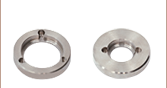
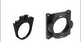
Thorlabs' retaining rings are used to secure unmounted optics within lens tubes or optic mounts. These rings are secured in position using a compatible spanner wrench. For flat or low-curvature optics, standard retaining rings manufactured from anodized aluminum are available from Ø5 mm to Ø4". For high-curvature optics, extra-thick retaining rings are available in Ø1/2", Ø1", and Ø2" sizes.
Extra-thick retaining rings offer several features that aid in mounting high-curvature optics such as aspheric lenses, short-focal-length plano-convex lenses, and condenser lenses. As shown in the animation to the right, the guide flange of the spanner wrench will collide with the surface of high-curvature lenses when using a standard retaining ring, potentially scratching the optic. This contact also creates a gap between the spanner wrench and retaining ring, preventing the ring from tightening correctly. Extra-thick retaining rings provide the necessary clearance for the spanner wrench to secure the lens without coming into contact with the optic surface.
| Posted Comments: | |
Pattabhi Dyta
(posted 2024-08-06 22:39:39.883) Hi,
What would be the acceptance angle (in degrees) and image circle formed (mm) for the lenses - LA1026 and LA1036 cdolbashian
(posted 2024-08-14 10:59:30.0) Thank you for reaching out to us with this inquiry. This depends highly on your application and experimental geometry. Is this an imaging application or simply a laser-focusing application. I have contacted you directly to discuss the various application-specific considerations which would contribute to accurately answering these questions. Liu Shaokun
(posted 2024-01-22 21:42:50.067) We have purchased a batch of plano-convex lenses made of N-BK7 glass, and we are uncertain about their power handling capabilities. Our laser has a power of 105W, operates continuously with a Gaussian beam profile and a waist radius of 5mm. Could you please confirm if these lenses can be safely used with our laser system? jpolaris
(posted 2024-01-25 06:22:38.0) Thank you for contacting Thorlabs. We have not measured the continuous wave laser induced damage threshold for the bulk NBK-7 substrate that these lenses are made from. Luckily, there is a lot of information about this from other researchers and manufacturers. LIDT is wavelength dependent, but it will be on the order of 100's of kW/(cm^2) for uncoated NBK-7, whereas your power density is around 1 kW/(cm^2) for a Gaussian profile. Just be sure your lenses are very clean. If any dust is present, it will burn. Kimi Huang
(posted 2023-07-06 11:36:05.007) what is the surface roughness of the lens? cdolbashian
(posted 2023-07-13 01:51:51.0) Thank you for contacting Thorlabs! We do not have surface roughness. We do however spec an irregularity tolerance of λ/4. Heesoo Uhm
(posted 2019-10-07 14:39:26.21) Dear Thorlab,
I am Heesoo Uhm, a postdoc in Prof. Achillefs Kapanidis lab in Oxford University.
I want to request quotations for custom focal length lens.
Based on LA1207(12.7mm diameter, 100mm focal length), what I want for focal lengths are 80 mm, 90 mm and 110 mm.
Please let me know how to get these custom lens for different focal lengths.
Thank you.
Best regards,
Heesoo Uhm. DJayasuriya
(posted 2019-11-06 03:13:57.0) Thank you for contacting Thorlabs, it looks like our techsupport team has contacted you regarding this request. For future custom requests please contact techsupport@thorlabs.com or use click the "Request Quote" button above our feedback section. user
(posted 2017-03-15 16:29:36.98) Would be great if all lenses/optics came with a sheet of several stick on labels with the product number, and relevant specs, like focal length, coating etc.
Usually the first thing I (and many other people) do when taking an optic out of the box is to mount it and then make a label for it. tfrisch
(posted 2017-03-23 10:17:29.0) Hello, thank you for contacting Thorlabs. I have posted this idea in our internal engineering forum. I agree that this could be useful. wilsen4verminator
(posted 2015-06-28 12:55:09.56) hi, i would like to know which lens has the dioptre value of 0.0- 1.0, and are this lens suitable for underwater use such as underwater welding ,thank you besembeson
(posted 2015-07-22 07:09:18.0) Response from Bweh at Thorlabs USA: You can calculate the lens power (in diopter) by taking the inverse of the focal length (1/f). Note that the focal length values we specify are in air, which will be different when the lens is used under water. mchen
(posted 2014-03-11 15:20:15.06) Can you provide BK7 lenses with D coating? Thanks, Mike besembeson
(posted 2014-03-13 01:18:06.0) Response from Bweh E at Thorlabs: Thanks for contacting Thorlabs. We can certainly provide N-BK7 lenses (N-BK7 is the RoHS compliant BK7)with the D-coating (R<1%, 1.8-2.4um). Note however that the transmission of N-BK7 substrate starts to decrease beyond 2µm (see "graph" tab at the following link: http://www.thorlabs.com/newgrouppage9.cfm?objectgroup_id=112) so even with the D-AR coating expect your transmission not to be uniform across 1.8-2.4 microns. I will send you separate email to follow up on the specific lenses you would like coated if this decrease in transmission is not a concern to you. Alternative materials to consider will be CaF2 (http://www.thorlabs.com/newgrouppage9.cfm?objectgroup_id=5669) and MgF2 (http://www.thorlabs.com/newgrouppage9.cfm?objectgroup_id=901) lenses, which we also provide. tor
(posted 2010-11-23 15:29:25.0) Response from Tor at Thorlabs to johnybaptista: Thank you for your interest in our lenses. I will contact you directly for more information so I can help you identify the most suitable lens for your application. johnybaptista
(posted 2010-11-23 10:22:56.0) Hello!
I´m constructing one laser distance measurement(rangefinder)and i I need help to know the better lense.
Thank you jens
(posted 2010-02-05 14:33:12.0) A reply from Jens at Thorlabs: the focal lenght for LA1986-C at 1070nm is
BFL = 124.9mm
EFL = 127.0mm jens
(posted 2010-02-05 12:22:44.0) A reply from Jens at Thorlabs: thanks for the notification. The link has been fixed. we are currently calculating the f/fb data at 1070nm and I will send it over to you in a little bit. gspaldin
(posted 2010-02-05 11:36:21.0) At:
http://www.thorlabs.com/NewGroupPage9.cfm?ObjectGroup_ID=112
The Tutorial tab graph claims you download data by clicking on it, but that is a BAD LINK. -What are the focal lengths (f and fb) at 1070nm for LA1986-C? Laurie
(posted 2008-10-13 14:54:29.0) Response from Laurie at Thorlabs to krishe80: Thank you for your feedback. The surface flatness is ~lambda/2 on the spherical side and ~lambda/4 on the flat side. The scratch-dig for the plano-convex lenses is 40/20. We will correct the inconsistency in our catalog. If you have further questions, please let us know. krishe80
(posted 2008-10-12 12:27:14.0) what is the surface accuracy on these lenses? Also in catalog scratch dig is 60-40 on website it says 40-20 which one is right? chris.koresko
(posted 2008-02-25 13:46:17.0) It would be nice if I could download a Zemax lens catalog (its not built into my copy of Zemax). technicalmarketing
(posted 2007-08-24 12:28:00.0) The lenses are now in order of increasing focal length within each lens diameter class and this page should be easier to find via the search engine. As always, we appreciate the presentation feedback and would like to thank you for the time you spent to make our website better. acable
(posted 2007-08-23 19:30:58.0) The lenses are sorted by Dia and then by Item# which makes it really hard to sort through the list, please sort by Dia and then by focal length then by coating. acable
(posted 2007-07-27 15:39:28.0) I had to work at finding the link for this page. Searched on Plano Convex Lens, then Plano Convex, then 3rd try of Plano-Convex finally got me a link. |
| Item #a | Diameter (mm) |
Focal Length (mm) |
Diopterb | Radius of Curvature (mm) |
Center Thickness (mm) |
Edge Thickness (mm) |
Back Focal Length (mm) |
Reference Drawing |
|---|---|---|---|---|---|---|---|---|
| LA1024 | 2.0 | 4.0 | +250.0 | 2.1 | 1.0 | 0.7 | 3.34 |  |
| LA1026 | 2.0 | 6.0 | +166.7 | 3.1 | 1.0 | 0.8 | 5.34 |
| Item #a | Diameter (mm) |
Focal Length (mm) |
Diopterb | Radius of Curvature (mm) |
Center Thickness (mm) |
Edge Thickness (mm) |
Back Focal Length (mm) |
Reference Drawing |
|---|---|---|---|---|---|---|---|---|
| LA1036 | 3.0 | 6.0 | +166.7 | 3.1 | 1.5 | 1.0 | 5.01 | |
| LA1039 | 3.0 | 9.0 | +111.1 | 4.7 | 1.5 | 1.2 | 8.01 |
| Item #a | Diameter (mm) |
Focal Length (mm) |
Diopterb | Radius of Curvature (mm) |
Center Thickness (mm) |
Edge Thickness (mm) |
Back Focal Length (mm) |
Reference Drawing |
|---|---|---|---|---|---|---|---|---|
| LA1116 | 6.0 | 10.0 | +100.0 | 5.2 | 2.5 | 1.5 | 8.3 | |
| LA1470 | 6.0 | 12.0 | +83.3 | 6.2 | 2.3 | 1.5 | 10.5 | |
| LA1222 | 6.0 | 14.9 | +66.7 | 7.7 | 2.1 | 1.5 | 13.6 | |
| LA1700 | 6.0 | 29.9 | +33.3 | 15.5 | 1.8 | 1.5 | 28.7 |
| Item #a | Diameter (mm) |
Focal Length (mm) |
Diopterb | Radius of Curvature (mm) |
Center Thickness (mm) |
Edge Thickness (mm) |
Back Focal Length (mm) |
Reference Drawing |
|---|---|---|---|---|---|---|---|---|
| LA1576 | 9.0 | 12.0 | +83.3 | 6.2 | 3.4 | 1.5 | 9.7 | |
| LA1472 | 9.0 | 19.9 | +50.0 | 10.3 | 2.5 | 1.5 | 18.3 |
| Item #a | Diameter | Focal Length (mm) |
Diopterb | Radius of Curvature (mm) |
Center Thickness (mm) |
Edge Thickness (mm) |
Back Focal Length (mm) |
Reference Drawing |
|---|---|---|---|---|---|---|---|---|
| LA1540 | 1/2" | 14.9 | +66.7 | 7.7 | 5.1 | 1.8 | 11.6 | |
| LA1074 | 1/2" | 19.9 | +50.0 | 10.3 | 4.0 | 1.8 | 17.3 | |
| LA1560 | 1/2" | 24.9 | +40.0 | 12.9 | 3.5 | 1.8 | 22.6 | |
| LA1289 | 1/2" | 29.9 | +33.3 | 15.5 | 3.2 | 1.8 | 27.8 | |
| LA1304 | 1/2" | 39.9 | +25.0 | 20.6 | 2.8 | 1.8 | 38.0 | |
| LA1213 | 1/2" | 49.8 | +20.0 | 25.8 | 2.6 | 1.8 | 48.1 | |
| LA1207 | 1/2" | 99.7 | +10.0 | 51.5 | 2.2 | 1.8 | 98.2 |
| Item #a | Diameter (mm) |
Focal Length (mm) |
Diopterb | Radius of Curvature (mm) |
Center Thickness (mm) |
Edge Thickness (mm) |
Back Focal Length (mm) |
Reference Drawing |
|---|---|---|---|---|---|---|---|---|
| LA1859 | 18.0 | 19.9 | +50.0 | 10.3 | 7.1 | 1.8 | 15.3 | |
| LA1270 | 18.0 | 24.9 | +40.0 | 12.9 | 5.5 | 1.8 | 21.3 | |
| LA1085 | 18.0 | 29.9 | +33.3 | 15.5 | 4.7 | 1.8 | 26.8 | |
| LA1119 | 18.0 | 49.8 | +20.0 | 25.8 | 3.4 | 1.8 | 47.6 |
| Item #a | Diameter (mm) |
Focal Length (mm) |
Diopterb | Radius of Curvature (mm) |
Center Thickness (mm) |
Edge Thickness (mm) |
Back Focal Length (mm) |
Reference Drawing |
|---|---|---|---|---|---|---|---|---|
| LA1252 | 25.0 | 25.4 | +39.4 | 13.1 | 11.7 | 2.5 | 17.7 | |
| LA1255 | 25.0 | 50.1 | +20.0 | 25.8 | 5.3 | 2.07 | 46.6 | |
| LA1257 | 25.0 | 74.9 | +13.3 | 38.6 | 4.10 | 2.02 | 72.2 | |
| LA1251 | 25.0 | 100.0 | +10.0 | 51.5 | 3.60 | 2.06 | 97.6 | |
| LA1253 | 25.0 | 200.0 | +5.0 | 103.0 | 2.80 | 2.04 | 198.1 |
| Item #a | Diameter | Focal Length (mm) |
Diopterb | Radius of Curvature (mm) |
Center Thickness (mm) |
Edge Thickness (mm) |
Back Focal Length (mm) |
Reference Drawing |
|---|---|---|---|---|---|---|---|---|
| LA1951 | 1" | 25.3 | +39.4 | 13.1 | 11.7 | 1.8 | 17.6 | |
| LA1805 | 1" | 29.9 | +33.3 | 15.5 | 8.6 | 2.0 | 24.2 | |
| LA1027 | 1" | 34.9 | +28.6 | 18.0 | 7.2 | 2.0 | 30.1 | |
| LA1422 | 1" | 39.9 | +25.0 | 20.6 | 6.4 | 2.0 | 35.7 | |
| LA1131 | 1" | 49.8 | +20.0 | 25.8 | 5.3 | 2.0 | 46.3 | |
| LA1134 | 1" | 59.8 | +16.7 | 30.9 | 4.7 | 2.0 | 56.7 | |
| LA1608 | 1" | 74.8 | +13.3 | 38.6 | 4.1 | 2.0 | 72.0 | |
| LA1509 | 1" | 99.7 | +10.0 | 51.5 | 3.6 | 2.0 | 97.3 | |
| LA1986 | 1" | 124.6 | +8.0 | 64.4 | 3.3 | 2.0 | 122.4 | |
| LA1433 | 1" | 149.5 | +6.7 | 77.3 | 3.1 | 2.0 | 147.5 | |
| LA1229 | 1" | 174.4 | +5.7 | 90.1 | 2.9 | 2.0 | 172.5 | |
| LA1708 | 1" | 199.3 | +5.0 | 103.0 | 2.8 | 2.0 | 197.5 | |
| LA1461 | 1" | 249.2 | +4.0 | 128.8 | 2.6 | 2.0 | 247.4 | |
| LA1484 | 1" | 299.0 | +3.3 | 154.5 | 2.5 | 2.0 | 297.3 | |
| LA1172 | 1" | 398.7 | +2.5 | 206.0 | 2.4 | 2.0 | 397.1 | |
| LA1908 | 1" | 498.3 | +2.0 | 257.5 | 2.3 | 2.0 | 496.8 | |
| LA1978 | 1" | 747.5 | +1.3 | 386.3 | 2.2 | 2.0 | 746.1 | |
| LA1464 | 1" | 996.7 | +1.0 | 515.1 | 2.2 | 2.0 | 995.3 | |
| LA1254c | 1" | 1500.0 | +0.7 | 775.2 | 2.1 | 2.0 | 1498.6 | |
| LA1258c | 1" | 2000.0 | +0.5 | 1033.6 | 2.1 | 2.0 | 1998.6 | |
| LA1259c | 1" | 2500.0 | +0.4 | 1292.0 | 2.1 | 2.0 | 2498.6 |
| Item #a | Diameter (mm) |
Focal Length (mm) |
Diopterb | Radius of Curvature (mm) |
Center Thickness (mm) |
Edge Thickness (mm) |
Back Focal Length (mm) |
Reference Drawing |
|---|---|---|---|---|---|---|---|---|
| LA1274 | 30.0 | 39.9 | +25.0 | 20.6 | 9.0 | 2.5 | 34.0 | |
| LA1102 | 30.0 | 49.8 | +20.0 | 25.8 | 7.3 | 2.5 | 45.0 | |
| LA1765 | 30.0 | 74.8 | +13.3 | 38.6 | 5.5 | 2.5 | 71.1 | |
| LA1031 | 30.0 | 99.7 | +10.0 | 51.5 | 4.7 | 2.5 | 96.5 | |
| LA1907 | 30.0 | 149.5 | +6.7 | 77.3 | 3.1 | 1.6 | 147.5 | |
| LA1541 | 30.0 | 199.3 | +5.0 | 103.0 | 2.8 | 1.7 | 197.5 | |
| LA1832 | 30.0 | 249.2 | +4.0 | 128.8 | 2.6 | 1.7 | 247.4 | |
| LA1419 | 30.0 | 299.0 | +3.3 | 154.5 | 2.5 | 1.8 | 297.3 | |
| LA1237 | 30.0 | 498.3 | +2.0 | 257.5 | 2.3 | 1.8 | 496.8 |
| Item #a | Diameter | Focal Length (mm) |
Diopterb | Radius of Curvature (mm) |
Center Thickness (mm) |
Edge Thickness (mm) |
Back Focal Length (mm) |
Reference Drawing |
|---|---|---|---|---|---|---|---|---|
| LA1385 | 1.5" | 50.0 | +20.0 | 25.8 | 10.9 | 2.5 | 42.8 | |
| LA1386 | 1.5" | 75.0 | +13.3 | 38.8 | 7.5 | 2.5 | 70.1 | |
| LA1387 | 1.5" | 100.0 | +10.0 | 51.7 | 6.1 | 2.5 | 96.0 | |
| LA1388 | 1.5" | 150.0 | +6.7 | 77.5 | 4.9 | 2.5 | 146.8 | |
| LA1389 | 1.5" | 200.0 | +5.0 | 103.4 | 4.3 | 2.5 | 197.2 |
| Item #a | Diameter | Focal Length (mm) |
Diopterb | Radius of Curvature (mm) |
Center Thickness (mm) |
Edge Thickness (mm) |
Back Focal Length (mm) |
Reference Drawing |
|---|---|---|---|---|---|---|---|---|
| LA1401 | 2" | 59.8 | +16.7 | 30.9 | 16.3 | 3.0 | 49.1 | |
| LA1145 | 2" | 74.8 | +13.3 | 38.6 | 12.5 | 3.0 | 66.5 | |
| LA1050 | 2" | 99.7 | +10.0 | 51.5 | 9.7 | 3.0 | 93.3 | |
| LA1384 | 2" | 124.6 | +8.0 | 64.4 | 8.2 | 3.0 | 119.2 | |
| LA1417 | 2" | 149.5 | +6.7 | 77.3 | 7.3 | 3.0 | 144.7 | |
| LA1399 | 2" | 174.4 | +5.7 | 90.1 | 6.7 | 3.0 | 170.0 | |
| LA1979 | 2" | 199.3 | +5.0 | 103.0 | 6.2 | 3.0 | 195.3 | |
| LA1301 | 2" | 249.2 | +4.0 | 128.8 | 5.5 | 3.0 | 245.5 | |
| LA1256 | 2" | 299.0 | +3.3 | 154.5 | 5.1 | 3.0 | 295.6 | |
| LA1725 | 2" | 398.7 | +2.5 | 206.0 | 4.6 | 3.0 | 395.7 | |
| LA1380 | 2" | 498.3 | +2.0 | 257.5 | 4.3 | 3.0 | 495.5 | |
| LA1727 | 2" | 747.5 | +1.3 | 386.3 | 3.8 | 3.0 | 745.0 | |
| LA1779 | 2" | 996.7 | +1.0 | 515.1 | 3.6 | 3.0 | 994.3 |
| Item #a | Diameter (mm) |
Focal Length (mm) |
Diopterb | Radius of Curvature (mm) |
Center Thickness (mm) |
Edge Thickness (mm) |
Back Focal Length (mm) |
Reference Drawing |
|---|---|---|---|---|---|---|---|---|
| LA1740 | 75.0 | 84.7 | +11.7 | 43.8 | 24.2 | 3.0 | 68.8 | |
| LA1238 | 75.0 | 99.7 | +10.0 | 51.5 | 19.2 | 3.0 | 87.0 | |
| LA1002 | 75.0 | 149.5 | +6.7 | 77.3 | 12.7 | 3.0 | 141.1 | |
| LA1353 | 75.0 | 199.3 | +5.0 | 103.0 | 10.1 | 3.0 | 192.7 |