 Products Home
6-Axis NanoMax™ NanoPositioning Flexure Stages
- Six Independent Degrees of Freedom: X, Y, Z, Pitch, Yaw, and Roll
- Modular High-Resolution Drive Options
- Open- and Closed-Loop Piezo Versions
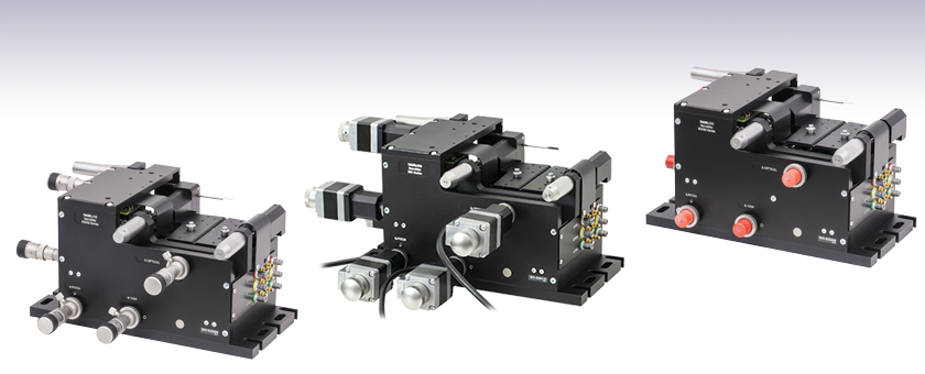
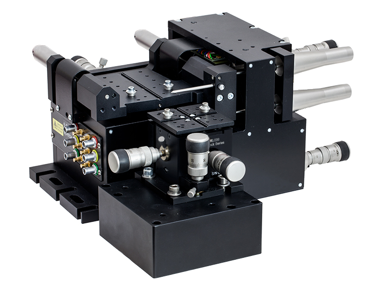
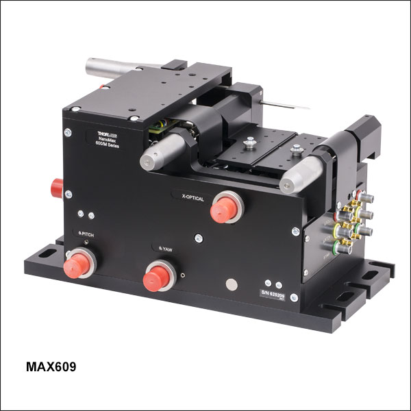
MAX609
No Actuators,
User Configurable
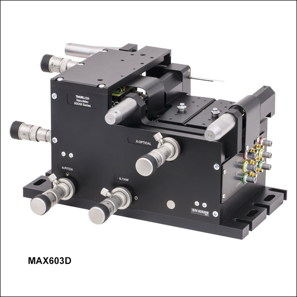
MAX603D
Differential Micrometers
US Patent 6,467,762
MAX683
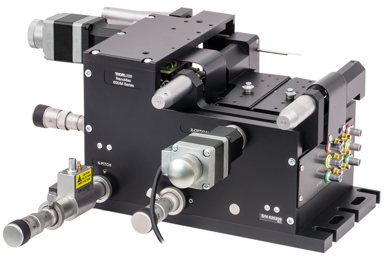
Stepper Motors


Please Wait
Click to Enlarge
Figure 1.1 In the Above Application, a 3-Axis NanoMax Flexure Stage is Aligned in Front of a 6-Axis Stage at the Proper 112.5 mm Deck Height Using an AMA554
Height Adapter
| Table 1.2 Common Specificationsa | ||
|---|---|---|
| Travel | X, Y, Z | 4 mm (0.16") |
| θx, θy, θz | 6° (105 mrad) | |
| Travel Mechanism | Parallel Flexure | |
| Deck Height (Nominal) | 112.5 mm (4.43") | |
| Optical Axis Height (Nominal) | 125 mm (4.92") | |
| Load Capacity (Max) | 1 kg (2.2 lbs) | |
| Max Arcuate Displacement | 80 µm | |
| RMS Repeatability | 30 nm over 30 μm 0.1% Over Full Travel Range |
|
| Thermal Stability | 1 µm/°C | |
| Stiffness | X, Z | 1 N/µm |
| Y | 0.5 N/µm | |
| Top Plate Mounting Holes |
Imperial Plate |
|
| Metric Plate |
||
Features
- 4 mm (0.16") of X, Y, and Z Travel
- 6° (105 mrad) of θx, θy, θz (Roll, Pitch, and Yaw) Travel
- Common Pivot Point for All Rotational Degrees-of-Freedom Simplifies Alignment and Reduces Cross Talk
- Parallel Flexure Design Ensures Smooth Continuous Motion and Long-Term Stability
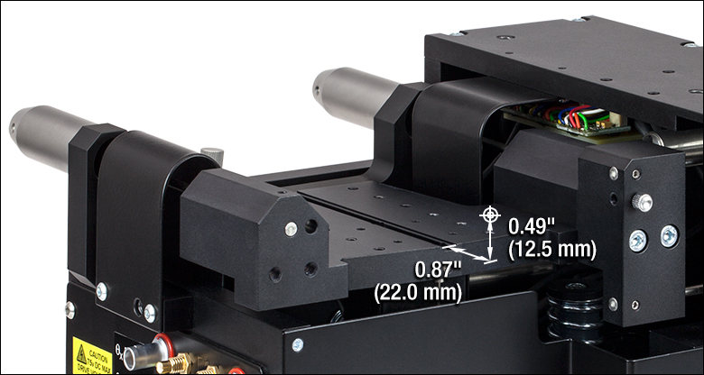
- Grooved Top Plate Ensures Alignment of Multi-Axis Stage Accessories
- Piezo Options Provide up to 1 nm Resolution
- High Stiffness Flexure Design:
- X and Z: 1 N/µm
- Y: 0.5 N/µm
- High Resonant Frequency: >130 Hz (±10%)
- Monolithic, Single Moving Platform Design
- All Adjusters Coupled to the Base to Minimize Crosstalk
- Modular Design for Interchanging Actuators
- Low Maintenance Mechanism for Low Total Cost of Ownership
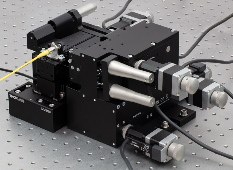
Thorlabs' 6-axis NanoMax™ Nanopositioning Flexure Stages are ideal for use in fiber launch systems or applications that require sub-micron resolution. Each unit provides 4 mm (0.16") of X, Y, and Z travel and 6° (105 mrad) of θx, θy, and θz travel with a maximum load capacity of 1 kg (2.2 lbs). Versions are available with or without preconfigured piezo actuators and differential or stepper motor actuators. The nominal deck height of the stage is 112.5 mm (4.43"), which matches that of our 112.5 mm tall 5-axis stage kits. Adapter plates are available for increasing the 62.5 mm deck height of our 3-axis and 4-axis flexure stages to 112.5 mm, enabling compatibility with our 6-axis stages. Our MVSN1(/M) motorized vertical stage can be used with our 6-axis stages through the use of an MVSNB(/M) height spacer (see Figure 1.5).
The parallel flexure design ensures precise, smooth, continuous motions with negligible friction. For complex, multi-axis positioning, parallel flexure stages that incorporate three or more degrees of freedom into a single compact unit provide significantly improved performance over serialized stacks of translation stages. See the Design Features tab for more information.
A powerful tool for nanopositioning, our 6-axis NanoMax stages offer two innovative features: a common point of rotation and a patented design that allows all actuators to be coupled directly to the base to minimize any unwanted motion in the system.
Click to Enlarge
Figure 1.3 The tip of a removable stainless steel probe marks the stage's common pivot point for all rotational axes.

Click to Enlarge
Figure 1.4 In this Fiber Coupling Application, a Laser Diode is Mounted in Front of a 6-Axis Stage Using an AMA029D Extension Platform
Common Point of Rotation
Each 6-Axis NanoMax stage has a stainless steel probe in front of the moving platform, as shown in Figure 1.3, indicating the common pivot point for all rotational axes. Having a common pivot point for all rotational axes reduces alignment time of a system by eliminating need for compensating lateral movement when adjusting θx, θy, and θz. If the moving platform is translated from its position, the pivot point also moves relative to the base, retaining its position relative to the moving platform. The nominal position of this point is in the mechanical drawing, which can be found by clicking on the blue info icon (![]() ) in Table 1.2. See the Design Features Tab for more information.
) in Table 1.2. See the Design Features Tab for more information.
Precision Drives
Stages that are pre-configured with differential micrometer actuators or stepper motor actuators are offered below for out-of-the-box operation. The modular design of our 6-axis NanoMax stages allows the drives to be removed and replaced at any time. For compatible drive options, please see the Drives tab. The drives are coupled directly to the base to minimize any unwanted motion in the system. This feature is ideal for any application requiring sub-micron resolution. For nanopositioning applications, we have versions with internal piezoelectric actuators.
Piezo Options
The option for open- or closed-loop piezos allows these stages to achieve nanometer resolution. The piezoelectric actuators are built into the stage, have 30 µm of travel, and can be controlled using many of our open- or closed-loop piezo controllers (see the Specs tab for all compatible controllers). When these stages are coupled with a NanoTrak controller (e.g. K-Cubes, benchtop, or rack system module), the system becomes a powerful auto-alignment solution that maintains optical throughput and eliminates coupling efficiency loss due to thermal drift or other external forces. These piezo stages include six PAA100 Drive Cables and, in the case of closed-loop systems, six PAA622 Feedback Converter Cables.
 Click to Enlarge
Figure 1.5 The MVSN1 Motorized Vertical Stage Used with a MAX681 6-Axis Stage
Stages with open-loop piezo actuators do not have a strain gauge displacement sensor and are ideal for applications requiring positioning resolution down to 20 nm. Versions with closed-loop piezo actuators have internal strain gauge displacement sensors that provide a feedback voltage signal that is linearly proportional to the displacement of the piezoelectric element. This feedback signal increases the resolution to 5 nm and can be used to compensate for the hysteresis, creep, and thermal drift that is inherent in all piezoelectric elements, making these stages an excellent choice for applications requiring nanometer resolution.
Please note that the piezo mechanism uses contact with the micrometer drives in order to move the top platform. If for any reason the stage is operated with the micrometer drives removed, blanking plugs must be fitted before the piezo actuators can function. To order blanking plugs, please contact Tech Support.
Easy Alignment of Accessories
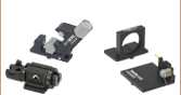
A wide range of accessories, shown in Table 1.6, is available to mount items such as microscope objectives, collimation packages, wave guides, fiber, and much more. These accessories can be easily aligned on the top platform of the 6-axis stage using a central keyway. This keyway in the top platform allows for rapid system reconfiguration while maintaining accessory alignment throughout the experiment.
| Table 1.6 Multi-Axis Stage Accessories | |||||||||||
|---|---|---|---|---|---|---|---|---|---|---|---|
 |
 |
 |
 |
 |
 |
 |
 |
 |
 |
 |
 |
| Fiber Mounts |
Fiber Rotators |
Waveguide Mounts |
Diode Mounts |
Fixed Mounts |
Kinematic Mounts |
Top Platesa |
Extension Platforms |
Fiber Chucks |
Slide Holdersa |
Kinematic Platforms |
Adapter Plates |
Stage Specifications
| Item # | MAX601D(/M) | MAX602D(/M) | MAX603D(/M) | MAX681(/M) | MAX682(/M) | MAX683(/M) | MAX607(/M)a | MAX608(/M)a | MAX609(/M)a | |
|---|---|---|---|---|---|---|---|---|---|---|
| Included Drives | DRV3 Differential Micrometer Drives | DRV208 Stepper Motor Actuatorsb | N/A | |||||||
| Travel | X, Y, Z | 4 mmc | ||||||||
| θx, θy, θz | 6° (105 mrad) | |||||||||
| Deck Height (Nominal) | 112.5 mm (4.43") | |||||||||
| Optical Axis Height (Nominal) | 125 mm (4.92") | |||||||||
| Load Capacity (Max) | 1 kg (2.2 lbs) | |||||||||
| Arcuate Displacement (Max) |
80 µm | |||||||||
| Thermal Stability | 1 µm/°C | |||||||||
| RMS Repeatability | 30 nm over 30 µm 0.1% Over full travel range |
|||||||||
| Stiffness | X-Axis Z-Axis |
1 N/µm | ||||||||
| Y-Axis | 0.5 N/µm | |||||||||
| Moving Top Plate Dimensions |
Imperial | |||||||||
| Metric | ||||||||||
| Item # | MAX601D(/M) | MAX602D(/M) | MAX603D(/M) | MAX681(/M) | MAX682(/M) | MAX683(/M) | MAX607(/M)a | MAX608(/M)a | MAX609(/M)a | |
| Theoretical Resolution with External Drives | ||||||||||
| X, Y | 1.5 µm | 1.8 nmd | N/A | |||||||
| Z | 1.0 µm | 1.2 nmd | ||||||||
| θx, θy, θz | 17 µrad | 0.021 µradd | ||||||||
| Item # | MAX601D(/M) | MAX602D(/M) | MAX603D(/M) | MAX681(/M) | MAX682(/M) | MAX683(/M) | MAX607(/M)a | MAX608(/M)a | MAX609(/M)a | |
| Internal Piezo Specifications | ||||||||||
| Control | N/A | Open Loop | Closed Loop | N/A | Open Loop | Closed Loop | N/A | Open Loop | Closed Loop | |
| Drive Voltage Range | 0 - 75 V | 0 - 75 V | 0 - 75 V | |||||||
| Travel | X, Y, Z | 30 µm | 30 µm | 30 µm | ||||||
| θx, θy, θz | 1.8 arcmin (0.52 mrad) |
1.8 arcmin (0.52 mrad) |
1.8 arcmin (0.52 mrad) |
|||||||
| Capacitance (Total)e | X, Y | 3.6 µF | 3.6 µF | 3.6 µF | ||||||
| Z, θx, θy, θz | 5.4 µF | 5.4 µF | 5.4 µF | |||||||
| Theoretical Resolutionf | X, Y, Z | 1.0 nm | 1.0 nm | 1.0 nm | ||||||
| θx, θy, θz | 0.018 µrad | 0.018 µrad | 0.018 µrad | |||||||
| Included Piezo Cables | Six PAA100 | Six PAA100 Six PAA622 |
Six PAA100 | Six PAA100 Six PAA622 |
Six PAA100 | Six PAA100 Six PAA622 |
||||
| Compatible Piezo Controllers | BPC303 MDT693B MPZ601 KPC101 KNA-VIS KNA-IR MNA601/IR BNT001/IR |
BPC303 MPZ601 KPC101 KNA-VIS KNA-IR MNA601/IR BNT001/IR |
BPC303 MDT693B MPZ601 KPC101 KNA-VIS KNA-IR MNA601/IR BNT001/IR |
BPC303 MPZ601 KPC101 KNA-VIS KNA-IR MNA601/IR BNT001/IR |
BPC303 MDT693B MPZ601 KPC101 KNA-VIS KNA-IR MNA601/IR BNT001/IR |
BPC303 MPZ601 KPC101 KNA-VIS KNA-IR MNA601/IR BNT001/IR |
||||
Differential Micrometer Specifications
| Item # | DRV3 |
|---|---|
| Travel Range | 8 mm (0.31") Coarse, 300 µm Fine |
| Resolution | 5.0 µm Coarse, 0.5 µm Fine |
| Coarse Adjustment |
500 µm/rev |
| Fine Adjustment |
50 µm/rev |
Stepper Motor Specifications
| Item # | DRV208 |
|---|---|
| Travel | 8 mm (0.3") |
| Unidirectional Repeatability | 3.6 µm |
| Bidirectional Repeatability | 5.0 µm |
| Absolute Accuracy | 17.1 µm |
| Maximum Force | 180 N |
| Maximum Velocity | 5 mm/s |
| Maximum Acceleration | 5 mm/s2 |
| Full Step Angle | 1.8° |
| Feedback | None |
| Limit Switches | Hall Effect |
| Lead Screw Pitch | 0.5 mm |
| Homing Repeatability | 13.5 µm |
| Motor Type | 2-Phase Stepper |
| Microsteps per Revolution of Leadscrew |
409 600 |
| Recommended Controllers | BSC203 MST602 |
Resonant Frequencies
| Resonant Frequency for Given Loads | ||
|---|---|---|
| Axis | Mass | Resonant Frequency |
| X | 25 g | 135 Hz |
| 55 g | 132 Hz | |
| 110 g | 128 Hz | |
| Y | 25 g | 122 Hz |
| 55 g | 119 Hz | |
| 110 g | 114 Hz | |
| Z | 25 g | 118 Hz |
| 55 g | 114 Hz | |
| 110 g | 110 Hz | |
Click to Enlarge
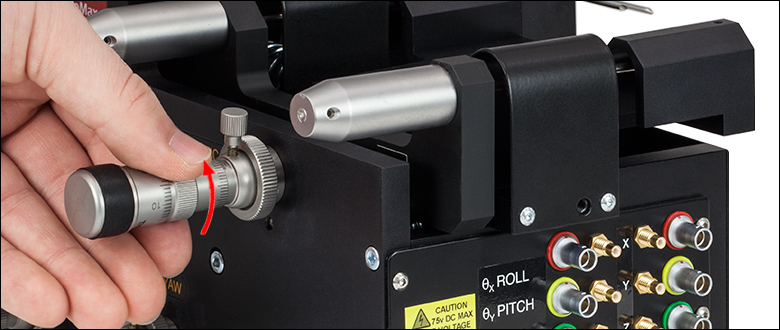
Step 2: Unscrew the knurled Knob and Remove the Actuator
Click to Enlarge
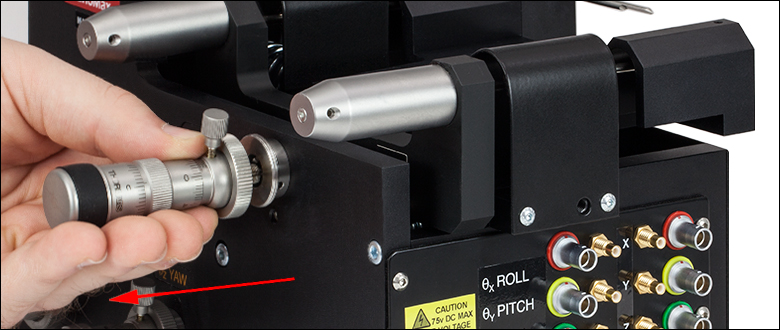
Step 1: Rotate the actuator counterclockwise to disengage the actuator from the platform.
Modular Drive Options
All 6-Axis NanoMax systems have a modular design that allows the drives to be removed and replaced at any time. This allows for mix-and-match customization of actuators depending on the amount of automation or resolution needed on each axis.
Replacing a drive is simple and can be done in three steps. First, retract the leadscrew of the actuator until it is no longer engaging the moving body of the stage. Then unscrew the knurled knob attaching the existing drive to the stage. Finally, attach the new drive to the stage using the same knurled knob.
The drives compatible with our 6-axis NanoMax stages are summarized below. While some drives have longer travel ranges, in all cases the NanoMax 6-axis stages have a travel range of 4 mm in X, Y, and Z and 6° of roll, pitch, and yaw. For more detailed information on each drive, please see the full presentation for our Stepper Motor Drive, Differential Micrometers and Thumbscrew Drives, or In-line Piezo Actuators.
| Item # | DRV004 | DRV3 | DRV208 | DRV120 |
| Click Image to Enlarge |
 |
 |
 |
 |
| Actuator Type | Thumbscrew | Differential Micrometera | Stepper Motorb | Piezoelectric with Feedback |
| Travel Range | 8 mm (0.31")c | Coarse: 8 mm (0.31")c Fine: 300 µm |
8 mm (0.31")c | 20 µm |
| Adjustment | 500 µm/revolution | Coarse: 500 µm/revolution Fine: 50 µm/revolution |
- | |
| Resolution | 1.0 µm | Coarse: 5.0 µm Fine: 0.5 µm |
200 steps/rev of Leadscrew | 5 nmd |
| Compatible Controllers | - | Benchtop: BSC200 Series Rack Module: MST602 |
Benchtop: BPC300 Series Rack Mount: MPZ601 K-Cubes: KNA-VIS, KNA-IR, or KPC101 |
|
Displacement Sensor
7-Pin LEMO Male
MAX603D(/M), MAX683(/M), MAX609(L)(/M)
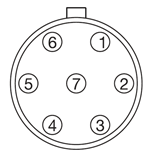
| Pin | Designation |
|---|---|
| 1 | +15 V |
| 2 | Oscillator + |
| 3 | 0 V |
| 4 | Signal Out - |
| 5 | Signal Out + |
| 6 | -15 V |
| 7 | Travel |
Piezo Drive Input
SMC Male
MAX602D(/M), MAX603D(/M),
MAX682(/M), MAX683(/M),
MAX608(L)(/M), MAX609(L)(/M)

Nominal Maximum Input Voltage: 75 V
Absolute Maximum Input Voltage: 100 V
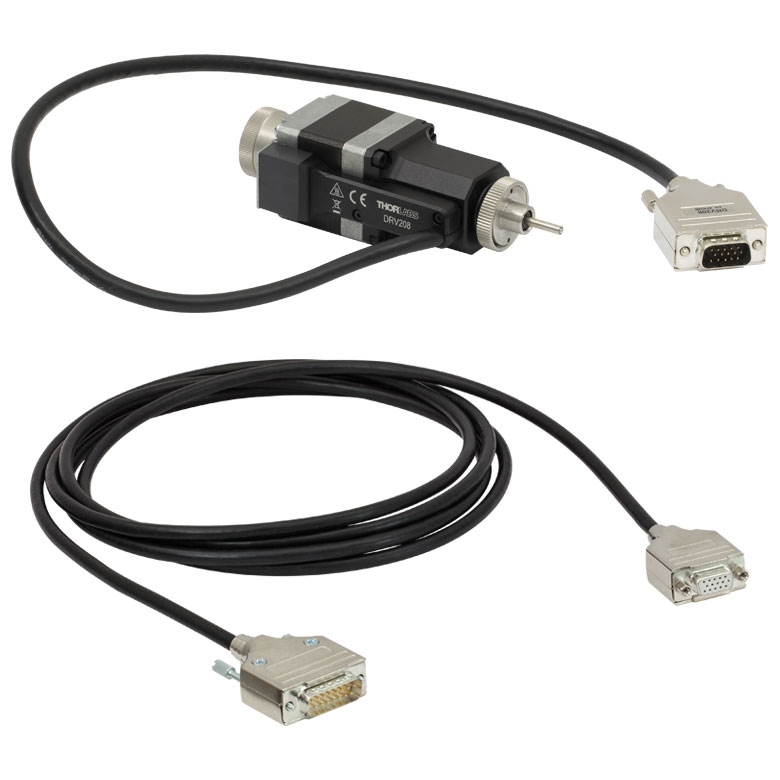
DRV208 Stepper Motor Connector Pins
D-Type Male
MAX681(/M), MAX682(/M), MAX683(/M)
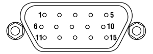
| Pin | Description | Pin | Description |
|---|---|---|---|
| 1 | Limit Switch 0 V | 9 | For Future Use |
| 2 | Limit Switch 0 V | 10 | +5 V |
| 3 | CW Limit Switch | 11 | - |
| 4 | Motor Phase B -ve | 12 | - |
| 5 | Motor Phase B +ve | 13 | +5 V |
| 6 | Motor Phase A -ve | 14 | - |
| 7 | Motor Phase A +ve | 15 | Ground |
| 8 | - | - | - |
6-Axis NanoMax Design Features
Patented Parallel Flexure Design

Click to Enlarge
Figure 5.1 Simplified Parallel Flexure Schematic
Parallel Flexure Platforms
For complex, multi-axis positioning, parallel flexure platforms (see Figure 5.1) that incorporate three or more degrees of freedom into a single compact unit provide significantly improved performance over serialized stacks of translation stages. Thorlabs’ patented parallel flexure technology lies at the heart of the NanoMax™ family of nanopositioning platforms. The starting point for the conceptual design is the observation that the motion of a rigid body has six unique degrees of freedom. Each actuator should subtract one degree of freedom from the body, so that the body is fully constrained with six actuators.
The parallel flexure design of the moving platform provides an unmatched combination of high stability and resolution in a six-axis nanopositioner. The mechanical stiffness is an order of magnitude higher than traditional serial flexure designs. In addition to those already mentioned, there are several other intrinsic advantages of the parallel flexure design: a much lower working height compared to stacked axis stages, additional resistance to external forces, and significant improvements to damping capabilities. Also, since there are fewer moving parts, there is a reduction in the inertia of the moving platform. This leads to excellent dynamic performance, making this product ideal for fast automated alignments.
This design also solves the problem of error buildup commonly seen in stacked (serial) designs as discussed below.
It is important to note that parallel flexures, like serial flexures, exhibit crosstalk or arcuate motion. As a stage is moved to either side of its central position, transverse arcuate displacements of approximately 20 μm per millimeter of travel occur. If several axes are moved at once, the combined effect can be greater; however, unlike the random positioning errors found in traditional stages, this crosstalk is highly predictable and hence can be corrected via small adjustments. Although these arcuate displacements are sometimes a concern, they rarely hinder the alignment of fibers or other optical components since optical beams rarely propagate collinearly with the axes of any stage to better than the scale of the arcuate motion. Furthermore, when using a NanoTrak™ Auto-Alignment Controller, these effects are automatically compensated for by the controller itself. However, if arcuate motion is a limiting parameter of a particular alignment or positioning application, its effects can also be compensated for with software.
Click to Enlarge
Figure 5.2 Simplified Stacked (Serial) Flexure Schematic
Traditional, Stacked (Serial) Multi-Axis Platforms
Multi-axis systems are traditionally built by stacking together a series of single axis mechanisms, as shown in Figure 5.2. As the number of axes increases, the design grows in complexity and becomes cumbersome. In addition, stacking drives reduces stiffness and can introduce a host of positioning errors.
All traditional designs of multi-axis stages (e.g., roller bearings, ball bearings, or flexures) suffer from the buildup of errors as stages are stacked. For a simple stacking of two stages, two main errors must be considered: cosine and Abbe. The cosine error arises when the axes of two stages are not aligned orthogonally to each other. The Abbe error arises from the finite height of the upper stage. Any angular roll, pitch, or yaw errors in the lower stage will be amplified by the overall height of the stacked system. The situation is particularly pronounced for a six-axis stage, where the mechanism providing the sixth degree of freedom is stacked atop five other stages. All of the errors in the preceding stages combine to make the overall volumetric accuracy of the complete stack far worse than the errors associated with any individual stage.
A parallel platform design solves the problem of error buildup. The design intent was to conceive the flexure as a rigid rod that has a flexible coupling at each end, leading to exactly two rotational degrees of freedom. This rod structure constrains the motion of the top plate by connecting it to the base. Six such rods provide the six independent constraints needed to restrain the stage, neither over- nor under-constraining it.
To actuate movement in the top plate, the ends of the flexure rods not attached to the top plate are connected to linear actuators. Linear translation occurs by moving the appropriate pairs of flexure rods in the same direction, whereas rotation occurs by moving the appropriate pairs of rods in opposite directions.
Reduced Part Count, Low Maintenance, and Long Lifetime
To transmit motion accurately, it has been shown that it is preferable to have as few moving parts acting in series as possible. At each interface between parts, microscopic imperfections can exist which will create friction between the parts. Such friction tends to be unpredictable and uncontrollable, making it the most undesirable element of any high-performance design. Parallel flexure platforms have very few moving parts and can transmit motion very precisely. Tests performed over 30 μm in 1 μm steps have yielded a root-mean-square bidirectional repeatability of 30 nm, or 0.1% of full range for the 6-axis NanoMax stages. These results are made possible by the inherently superior performance of the parallel flexure mechanism that eliminates static and kinematic friction within the platform.
During operation, 6-axis NanoMax platforms do not suffer appreciably from wear and tear due to the minimal number of moving parts. Since there are no bearings in the moving parts, there is no degradation of positioning performance with time. This also reduces the maintenance costs since the only parts that may require servicing are the drive actuators. Moreover, setups do not need to be completely disturbed for stage maintenance. Drives can be very easily and quickly swapped, minimizing system down time and inconvenience. However, when the actuator is removed the platform will move from its position.
Common Pivot Point for All Rotation Axes
Click to Enlarge
Figure 5.3 The tip of a removable stainless steel probe marks the stage's common pivot point for all rotational axes. Click here to see the mechanical drawing indicating the common pivot point.
Click for Details
Figure 5.4 The stainless steel probe can be removed at any time by loosening the knurled knob on the front of the stage
A unique mechanical feature of the 6-Axis NanoMax stages is the addition of a single common pivot point, shown in Figure 5.3, for all three of the rotation axes (θx, θy, θz) to simplify any alignment challenge. In practical terms, this means that the need to compensate lateral movement is nearly eliminated when making rotational adjustments to any axis. For complex alignments of planar optical devices this can vastly reduce the time required for optimizing a system.
Usually a fiber holder is attached so that the tip of the fiber is held at the common rotation point with all of the attached adjusters at the middle of their translation range. For instructions on positioning the top plate please see page 13 of the manual. If the moving platform is translated from its midpoint, the pivot point also moves relative to the base, retaining its position relative to the moving platform. Once the mounted accessories are aligned on the platform, the stainless steel probe can be removed by loosening the knob on the front of the unit, as shown in Figure 5.4.
Fixed, Modular, High-Resolution Actuators
Click to Enlarge
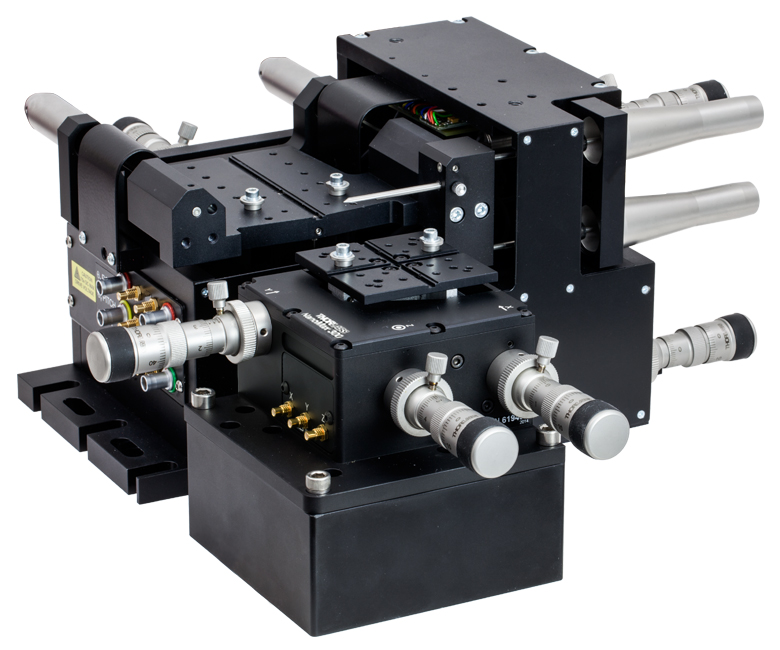
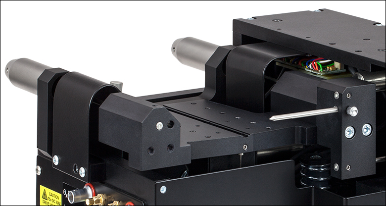
Figure 5.5 6-axis stage configured with various actuators. Please see the Drives tab for all options.
All actuators are connected directly to the base of the system rather than the moving top plate, thus minimizing unwanted motion within the system. Consequently, during manual operation, this allows operators to achieve a higher resolution with less skill. In motorized and automated applications, actuator vibration and shocks have little effect on the moving top plate.
The modular design of our 6-axis NanoMax stages allows the drives to be removed and replaced at any time. This allows for mix-and-match customization of actuators depending on the amount of automation or resolution needed on each axis.
Thorlabs offers a number of drive options including fine-thread thumbscrews, differential micrometers, motorized actuators, and piezo extenders. Figure 5.5 shows various drive options attached to different axes. This modularity allows the stage to be highly versatile for all applications. Versions are also available that have internal piezoelectric actuators giving 30 μm of travel with resolutions down to 1.0 nm, either open-loop or with strain gauge position feedback (closed loop). For increased performance and stability, the drive voltages are also controlled by built-in circuitry to compensate for thermal variations.
For all of our compatible drive options, please see the Drives tab. Pre-configured stages are also offered that have differential micrometers or stepper motor actuators for out-of-the-box manual or motorized operation, respectively.
Low Platform Height and Keyway Accessory Alignment
Click to Enlarge
Figure 5.7 In the Above Application, a 3-Axis MicroBlock Compact Flexure Stage is Aligned in Front of a 6-Axis Stage at the Proper 112.5 mm Deck Height Using an AMA554 Height Adapter
Click to Enlarge
Figure 5.6 In the Above Application, a 3-Axis NanoMax Flexure Stage is Aligned in Front of a 6-Axis Stage at the Proper 112.5 mm Deck Height Using an AMA554 Height Adapter
Thorlabs' 6-axis stages have a low platform height of 112.5 mm (4.43") for increased stability. This height also makes the 6-axis stage compatible with our 112.5 mm tall 5-axis stage kits. As shown in Figures 5.6 and 5.7, adapter plates are available for increasing the 62.5 mm deck height of our 3-axis and 4-axis flexure stages to 112.5 mm, enabling compatibility with our 6-axis stages.
A central keyway in the top platform allow for rapid system reconfiguration while maintaining accessory alignment. A wide range of accessories is available to mount items such as microscope objectives, collimation packages, wave guides, fiber, and much more.
| Posted Comments: | |
user
(posted 2025-03-26 06:20:33.843) Could I recommend putting together a photonic chip test station with varying levels of automation. Thorlabs sells nearly all the components so a list of what to get or a packaged system would be great! cstroud
(posted 2025-03-26 10:18:14.0) Thanks for reaching out and providing feedback. I will pass your comments onto our engineering team. Zhu Shuyu
(posted 2024-11-15 02:36:48.613) 尊敬的工程师:
您好!
上次您的答复对我来说很有帮助。
关于MAX603D我还有一些问题想咨询:
1.压电元件是不是就串联在DRV3千分尺的末端呢,sw三维图中好像没有体现出压电元件的位置
2.X, Oz,Ox, Y轴在千分尺的后面有Extension Tube, 但Z和Oy轴后面没有,请问这是为何,以及Extension Tube的作用是什么。
3.在使用过程中,手拧DRV3千分尺的调节如何跟压电元件逆压电效应产生的位移相配合呢,我是否需要一边调节DRV3千分尺,一边调节压电元件的电压,还是说,压电元件根据DRV3千分尺的位置自动调节?
祝您工作顺利! dnewnham
(posted 2024-11-25 07:35:18.0) Thank you for your feedback we will reach out to you directly to discuss it further. Zhu Shuyu
(posted 2024-11-13 15:12:03.723) 能否反馈一下MAX603D“获专利的平行挠性设计”的专利号,我希望能通过专利详细了解下。 tschofield
(posted 2024-11-13 10:28:23.0) Thank you for your inquiry. The patent number for this technology is US Patent 6,467,762. A member of our team will reach out to you directly. Kok Sing Lim
(posted 2023-01-16 13:45:30.273) Hi
I'm interested in your product MAX682/M.
There are 6 axes but the recommended controller BPC303 has three channels. Do I need two controllers to control the nanostages?
Would it be possible to have motorised X, Y and Z axes while there other three axes θx, θy, θz controlled using DRV3 Differential Micrometers ?
Appreciate your advice and recommendation JReeder
(posted 2023-01-17 04:39:16.0) Thank you for your enquiry and interest in our products. The BPC303 is our three Channel piezo controller, in order to use all 6 piezos in our 6 axis NanoMax stages simultaneously you will need to purchase two BPC303's. The NanoMax stages are fully modular with regards to the longer travel drives. If you wish to have X, Y and Z axis motorised using the DRV208 stepper motors and the θx, θy and θz controlled using DRV3 Differential Micrometers you can purchase one of the MAX60X stages without any pre-installed actuators and then purchase the actuators separately. This will then allow you to customise the combination of actuators that you use with this stage. Please note that for the DRV208 stepper motor actuators you will need one of our stepper motor controllers - as you are using the benchtop piezo controller, we would recommend that you use the benchtop stepper motor controller (BSC203). I have reached out to you to discuss your application further. Eden London
(posted 2022-04-27 15:18:26.843) Hello,
I'd like to know regarding control of the MAX683/M with Python when connected to the MST602 (which is in turn inserted into one of the 12 controller racks).
Is such a control scheme possible? we'd like to use this stage for automatic nm scale optical alignment.
Thanks. DJayasuriya
(posted 2022-05-04 03:29:06.0) Thank you for your inquiry. Yes this would be possible, we have got in touch with you directly to help with your request. Ryan Smith
(posted 2021-05-25 11:41:47.637) Hello,
Do you have information on how load capacity of this mount varies with placement of the load? I'm thinking of something similar to the graphs of load capacity hexapods are often specified with cwright
(posted 2021-05-26 06:30:21.0) Response from Charles at Thorlabs: Hello and thank you for your query. Unfortunately this is not data we can currently supply. I will reach out to you to discuss your intended application. Xu Lin
(posted 2020-11-11 10:11:56.24) Dear sir: I have some question for the Stepper Motor Controllers Type: BSC 201 with Motor Type : DRV 208 and Stage Type : MAX 681. The specification sheet shows that the theoretical resolution can reach 1.8 nm in x-axis. What does the theoretical mean? Does it mean it's just ideal? Our group want to realize Nano-positioning application. so is it okay for us to use the type above? or it's better to use the internal piezos? cwright
(posted 2020-11-12 08:08:46.0) Response from Charles at Thorlabs: Hello and thank you for your query. The theoretical resolution will be calculated using the pitch of the actuators lead screw, the rotation of the lead screw for a single microstep of the motor and the ratio between the movement of the actuator and movement of the flexure, for the axis in question, near to the centre of travel where the motion of a flexure is most linear. This is an ideal situation and assumes perfect motion of the lead screw. I will reach out to you to discuss your application and what would be most suitable. alfred
(posted 2016-09-12 11:08:21.167) Dear Sir:
I come from Chroma ATE Inc.
I have some question for this apt™ Stepper Motor Controllers Type:BSC203
with Motor Type :DRV001(see on the motor's connecter) and Stage Type :MAX604 - 6-Axis NanoMax Stage, Stepper Motors, No Piezos, Right-Handed(see on the stage's box)
1.I'd like to know device unit about the motor: (nm/Pulse?)
According to ThorLab official specification value:
a.Minimum Incremental Movement:60nm/pulse.Does device unit?
b.Lead Screw Pitch:0.5mm.Does express motor rotation one circle forward 0.5mm?
c.Microsteps per Revolution of Leadscrew:Does express motor rotation one circle need 409600pulse?
So (Lead Screw Pitch/Microsteps per Revolution of Leadscrew)=Minimum Incremental Movement,but 1.2nm is not equal 60nm ,why?
2.Kinesis software(Actuator set APT600L X Axis)
a.Step Size=0.5mm: motor rotation one circle forward 0.5mm? but autaul half circle I see.
b.Travel:8mm ,but I could move 12 mm (show on the current device postion).
Does I configuration error?
3.We use MAX604/M stage,I'd like to know (Roll,Pitch,Yaw) device unit.
I have seen MAX604/M Manual, but I'm not sure.
page:21
path:https://www.thorlabs.com/drawings/11c303460db0cce4-17B504EE-5056-010E-86CD5C9A5BF9295C/MAX604_M-Manual.pdf
Thank you. bwood
(posted 2016-09-12 11:49:35.0) Response from Ben at Thorlabs: Thank you for your feedback. I believe this relates to the conversion between microsteps to real world units. For the DRV001 connected to the BSC203, 1mm equates to 819200µs. I will be in direct contact with you so I can gather more details on your system, and troubleshoot you Kinesis issue in more detail. ngaber
(posted 2015-06-02 17:00:21.813) Dear Sir,
Don'y you provide a Left-Handed version from this stage:
6-Axis NanoMax Stage, Differential Drives, Closed-Loop Piezos, Right-Handed, Metric? cevered
(posted 2015-06-03 07:34:38.0) Response from Chris at Thorlabs: Yes, we can provide a left handed version of MAX603D/M at the same price. We will contact you directly via email with a quote. a.andreski
(posted 2015-02-04 02:18:52.783) Are the definitions of the rotational angles such that every successive rotation happens about the rotated coordinate system (intrinsic rotation) or the original one (extrinsic rotation)? Thanks! msoulby
(posted 2015-02-05 08:05:21.0) Response from Mike at Thorlabs: A unique mechanical feature of the NanoMax 600 Series is that there is a single common pivot point for all three of the rotation axes. In practical terms this means that the need for compensating lateral movement is nearly eliminated when making rotational alignment movements. The common pivot point is marked by a pin and can be viewed in the drawing link below http://www.thorlabs.de/thorcat/22800/MAX601D_M-AutoCADPDF.pdf a.andreski
(posted 2013-10-21 15:26:49.763) Is de RMS repeatability given in closed loop mode? msoulby
(posted 2013-10-23 09:02:00.0) Response from Mike at Thorlabs: Yes the RMS repeatability was measured in closed loop mode. jlow
(posted 2012-08-09 10:21:00.0) Response from Jeremy at Thorlabs: I will get in contact with you directly to look at your VI and resolve this issue. fontainenh
(posted 2012-08-08 15:06:44.0) I have a Nanomax 6-axis stage with DRV001 steppers. I need to have the z-axis translation very short beyond home position of 0.000 mm because my inverted microscope objective has a 0.35 mm working distance and it will strike the bottom of my window if it goes higher than that. The problem is that when I home my motors (using Labview 2011 ActiveX), the motor positions the platform about 2 mm above the location where the DRV001 first re-engages the stage when it homes and then the position gets initialized at that position to be 0.0000. I cannot translate to negative values, 0.000 is the minimum. This leaves my objective too far under the window (by about 1.65 mm). If I adjust the height of the objective upward to best focus, then do a subsequent home command, it lowers the platform (and window) and it crashes into my objective. I noticed the pitch on the z-axis loads as 0.5 mm, but if I change manually to 0.75 mm in APT User, then the z-axis home positioning seems to work correctly. But I have to do that manually. How can I change the settings so that the correct parameters load when launching my labview VI. apalmentieri
(posted 2010-01-11 11:48:12.0) A response from Adam at Thorlabs: Yes, the Max600 series can provide tip and tilt adjustments to help limit the defocusing of the substrate. However, the defocusing element also depends on the substrate being used and the sample size that you are imaging. Also, there may be a better stage system that we can provide which may be more compatible with your microscope. One system that you may want to consider is a MAX300 series stage with a APY002. I will email you directly to get more information about your setup. kim.feijen
(posted 2010-01-11 05:20:04.0) I would like to use the stage to adjust a substrate parallel to an objective of a microscope (remove tilt) and then translating it X and Y without defocussing the substrate. Is this possible? Laurie
(posted 2008-11-20 16:40:34.0) Response from Laurie at Thorlabs to amirhossein: Thank you for your interest in our 6-axis stages. Someone from our technical support staff will contact you and work with your directly to determine the best stage for your application. amirhossein.tehranchi
(posted 2008-11-14 14:52:23.0) Dear Sir/Madam,
I need a package for fiber to waveguide alignment including 2 six-axis stages without motors but including the piezos on x, y and z of them and necessary apparatus and controllers.
Meanwhile, how much does the cost differ with motors?
I need to have the possibility and the quotes with discount, ASAP as we are going to buy soon lots of equipments from THORLABS for our lab.
Regrads
Amirhossein Tehranchi
EED, L-6813 Lassonde Bldg.
Ecole Polytechnique
University of Montreal
Montreal H3T 1J4
Canada
514 340 4711 lsandstrom
(posted 2008-10-23 07:07:05.0) What is the tolerance on each axis with respect to the common pivor point? |
Multi-Axis Stage Selection Guide
Click to Enlarge
Figure 83A In the above application, a 3-Axis NanoMax flexure stage is aligned in front of a 6-axis stage at the proper 112.5 mm deck height using an AMA554 Height Adapter.
3-Axis Stages
Thorlabs offers three different 3-Axis Stage variations: NanoMax flexure stages, MicroBlock compact flexure stages, and RollerBlock long-travel stages. Each stage features a 62.5 mm nominal deck height. Our NanoMax line of 3-axis stages offers built-in closed- and open-loop piezos as well as modular drive options that include stepper motors, differential drives, or additional piezos. The MicroBlock stages are available with differential micrometer drives or fine thread thumbscrews; these drives are not removable. Finally, our RollerBlock stage drivers can be switched out for any actuator that has a Ø3/8" (9.5 mm) mounting barrel.
4- and 5-Axis Stages
Our 4- and 5-axis stages are ideal for the static positioning of waveguides or complex optical elements with respect to our 3-axis or 6-axis high-performance alignment stages. Thorlabs' 5-axis stages have nominal heights of 62.5 mm or 112.5 mm. The AMA554 Height Adapter can be used to raise the deck height of the 3-axis or 4-axis stages to 112.5 mm for compatibility with our 5-axis MicroBlock or 6-Axis NanoMax Stages.
6-Axis Stages
Thorlabs' 6-Axis NanoMax Nanopositioners are ideal for complex, multi-axis positioning and have a nominal deck height of 112.5 mm. These stages offer a common point of rotation and a patented parallel flexure design that allows all actuators to be coupled directly to the base to minimize any unwanted motion in the system. Built-in closed- and open-loop piezo options are available. A selection of modular drive options allows any axis to be manual or motorized with the option for external piezos. Our units without included actuators are also available in right- or left-handed configurations. To increase the stage height of the 3-axis stages to 112.5 mm, we recommend our AMA554 Height Adapter, shown in Figure 83A.
A complete selection and comparison of our multi-axis stages is available below.
3-Axis Stages
| Item # | MAX313D | MAX312D | MAX311D | MAX383 | MAX381 | MAX303 | MAX302 | MAX301 | MBT602 | MBT616D | RB13M | RBL13D | ||||||||
|---|---|---|---|---|---|---|---|---|---|---|---|---|---|---|---|---|---|---|---|---|
| Stage Type | NanoMax Flexure Stages | MicroBlock Compact Flexure Stages |
RollerBlock Long Travel Stages | |||||||||||||||||
| Included Drives | DRV3 Differential Micrometers | DRV208 Stepper Motor Actuators | N/A | Fine Thread Thumbscrews | Differential Micrometers | 148-801ST Micrometer Drives |
DRV304 Differential Micrometers |
|||||||||||||
| Built-in Piezos | N/A | Open Loop |
Closed Loop | N/A | Closed Loop | N/A | Open Loop | Closed Loop | N/A | N/A | ||||||||||
| Travel (X, Y, Z) | 4 mm (0.16") | 13 mm (0.51") | ||||||||||||||||||
| Deck Height (Nominal) | 62.5 mm (2.46") | |||||||||||||||||||
| Optical Axis Height (Nominal) | 75 mm (2.95") | |||||||||||||||||||
| Load Capacity (Max) | 1 kg (2.2 lbs) | 4.4 kg (9.7 lbs) | ||||||||||||||||||
| Thermal Stability | 1 µm/°C | - | ||||||||||||||||||
| Weight | 1.00 kg (2.20 lbs) | 0.64 kg (1.40 lbs) | 0.59 kg (1.30 lbs) | |||||||||||||||||
4-Axis Stages
| Item # | MBT401D MBT401D/M |
MBT402D MBT402D/M |
|
|---|---|---|---|
| Stage Type | 4-Axis Thin-Profile MicroBlock Device Stage | 4-Axis Low-Profile MicroBlock Device Stage | |
| Included Drives | Differential Micrometers | ||
| Built-in Piezos | N/A | ||
| Travel | Horizontal Axis (Y)a | 13 mm (0.51") | |
| Vertical Axis (Z) | 6 mm (0.24") | ||
| Pitch (θy) | ±5° | ||
| Yaw (θz) | ±5° | ||
| Deck Height (Nominal) | 62.5 mm (2.46") | ||
| Optical Axis Height (Nominal) | 75 mm (2.95") | ||
| Load Capacity (Max) | 0.5 kg (1.1 lbs) | ||
5-Axis Stages
| Item # | MBT401D (MBT401D/M) or MBT402D (MBT402D/M) with MBT501 |
PY005 | |
|---|---|---|---|
| Stage Type | 5-Axis MicroBlock Stage System | Compact 5-Axis Stage | |
| Included Drives | Differential Micrometers | 100 TPI Actuators | |
| Built-in Piezos | N/A | ||
| Travel | Optical Axis (X) | 13 mm (0.51") | 3 mm (0.12") |
| Horizontal Axis (Y) | 13 mm (0.51") | 3 mm (0.12") | |
| Vertical Axis (Z) | 6 mm (0.24") | 3 mm (0.12") | |
| Pitch (θy) | ±5° | ±3.5° | |
| Yaw (θz) | ±5° | ±5° | |
| Deck Height (Nominal) | 112.5 mm (4.43") | 62.5 mm (2.46")a | |
| Optical Axis Height (Nominal) | 125 mm (4.92") | 75 mm (2.95")a | |
| Load Capacity (Max) | 0.5 kg (1.1 lbs) | 0.23 kg (0.5 lbs) | |
6-Axis Stages
| Item # | MAX601D MAX601D/M |
MAX602D MAX602D/M |
MAX603D MAX603D/M |
MAX681 MAX681/M |
MAX682 MAX682/M |
MAX683 MAX683/M |
MAX607 MAX607/M MAX607La MAX607L/Ma |
MAX608 MAX608/M MAX608La MAX608L/Ma |
MAX609 MAX609/M MAX609La MAX609L/Ma |
|
|---|---|---|---|---|---|---|---|---|---|---|
| Stage Type | 6-Axis NanoMax Flexure Stage | |||||||||
| Included Drives | DRV3 Differential Micrometers | DRV208 Stepper Motor Actuators | N/A | |||||||
| Built-in Piezos | N/A | Open Loop | Closed Loop | N/A | Open Loop | Closed Loop | N/A | Open Loop | Closed Loop | |
| Travel | X, Y, Z | 4 mm (0.16") | ||||||||
| θx, θy, θz | 6° | |||||||||
| Deck Height (Nominal) | 112.5 mm (4.43") | |||||||||
| Optical Axis Height (Nominal) | 125 mm (4.92") | |||||||||
| Load Capacity (Max) | 1.0 kg (2.2 lbs) | |||||||||

 Zoom
Zoom| Item #a | MAX601D(/M) | MAX602D(/M) | MAX603D(/M) | |
|---|---|---|---|---|
| Manual Drive Specifications | ||||
| Included Drives | DRV3 Differential Micrometer Drives | |||
| Travel | X, Y, Z | Coarseb: 4 mm (0.16") Fine: 300 µm |
||
| θx, θy, θz | Coarse: 6° (105 mrad) Fine: 18 arcmin (5.2 mrad) |
|||
| Coarse Adjustmentc |
500 µm/rev | |||
| Fine Adjustmentc |
50 µm/rev | |||
| Piezo Specifications | ||||
| Control | N/A | Open Loop | Closed Loop | |
| Drive Voltage Range | 0 - 75 V | |||
| Travel Range | X, Y, Z | 30 µm | ||
| θx, θy, θz | 1.8 arcmin (0.52 mrad) | |||
| Theoretical Resolutiond |
X, Y, Z | 1.0 nm | ||
| θx, θy, θz | 0.018 µrad | |||
| Included Piezo Cables | Six PAA100 | Six PAA100 Six PAA622 |
||
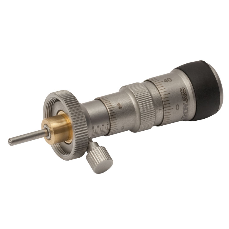
- Preconfigured with DRV3 Differential Micrometers for Manual Adjustments
- Available With or Without Internal Closed- or Open-Loop Piezos
- Optional Piezo Actuators Offer 30 µm of Travel
- Modular Design Allows Drives to be Removed and Replaced
- All Adjusters Coupled to the Base to Minimize Crosstalk
Thorlabs' 6-Axis NanoMax stages with Differential Adjusters provide 4 mm (0.16") of coarse X, Y, and Z travel with 300 µm of fine travel. They also provide 6° (105 mrad) of θx, θy, and θz (Roll, Pitch, and Yaw) Travel with
18 arcmin (5.2 mrad) of fine travel. The coarse adjuster has a scale with
10 µm graduations for a resolution of 5 µm. The fine adjuster has a scale with 1 µm graduations allowing for a resolution of 0.5 µm. This resolution and travel range make these stages ideal for optimizing the coupling efficiency in a fiber alignment or waveguide positioning system. The graduations also allow for a clear reference point for absolute positioning within a system. Please note that for the X- and Y-axis 1 mm of micrometer travel will translate to 1.5 mm of stage travel. Please see the manual for more information. The modular design of the included drives allows them to be replaced at any time; please see the Drives tab for more details and our full selection of compatible actuators.
In addition to the features above, the MAX602D(/M) and MAX603D(/M) NanoMax Stages incorporate open- and closed-loop piezoelectric actuators, respectively, with 30 µm of travel. The open-loop design does not contain an internal strain gauge sensor. The theoretical resolution of the piezo actuators is 1.0 nm for the X-, Y-, and Z-axis and 0.018 µrad for the θx, θy, and θz rotational axes. This feedback loop created when using our closed loop system is ideal for compensating for the hysteresis, creep, and thermal drift that is inherent to all piezoelectric elements. These piezo stages include six PAA100 Drive Cables and, in the case of closed-loop systems, six PAA622 Feedback Converter Cables.

 Zoom
Zoom| Item #a | MAX681(/M) | MAX682(/M) | MAX683(/M) | |
|---|---|---|---|---|
| Stepper Motor Drive Specifications | ||||
| Included Drives | DRV208 Stepper Motor Actuators | |||
| Travelb | X, Y, Z | 4 mm (0.16")c | ||
| θx, θy, θz | 6° (105 mrad) | |||
| Max Velocity | 5 mm/s | |||
| Max Acceleration | 5 mm/s2 | |||
| Included Motor Extension Cables |
Six PAA613 | |||
| Recommended Drivers | BSC203 and MST602 | |||
| Piezo Specifications | ||||
| Control | N/A | Open Loop | Closed Loop | |
| Drive Voltage Range | 0 - 75 V | |||
| Travel |
X, Y, Z | 30 µm | ||
| θx, θy, θz | 1.8 arcmin (0.52 mrad) | |||
| Theoretical Resolutiond |
X, Y |
1.0 nm | ||
| Z | 1.0 nm | |||
| θx, θy, θz | 0.018 µrad | |||
| Included Piezo Cables | Six PAA100 | Six PAA100 Six PAA622 |
||
- Preconfigured with DRV208 Stepper Motor Actuators for Automated Alignments
- Available With or Without Internal Closed- or Open-Loop Piezos
- Optional Piezo Actuators Offer 30 µm of Travel
- Modular Design Allows Drives to be Removed and Replaced
- All Adjusters Coupled to the Base to Minimize Crosstalk
Thorlabs' 6-Axis NanoMax Stages with stepper motor actuators provide 4 mm (0.16") of X, Y, and Z travel and 6° (105 mrad) of θx, θy, θz (Roll, Pitch, and Yaw) travel. The actuators can achieve a bidirectional repeatability of 5.0 µm. Hall effect limit switches provide a high repeatability ideal for homing the motors. This is critical for auto alignment applications that rely on a highly repeatable zero point. The high repeatability and small step size make these stages ideal for any high-precision automated fiber launch system or general application. The modular design of the included drives allows them to be replaced at any time; please see the Drives tab for more details and our full selection of compatible actuators. Each stage also includes six PAA613 3 m extension cables for the stepper motor actuators.
In addition to the features above, the MAX682(/M) and MAX683(/M) NanoMax Stages incorporate open- and closed-loop piezoelectric actuators, respectively, with 30 µm of travel. The open-loop design does not contain an internal strain gauge sensor. The theoretical resolution of the piezo actuators is 1.0 nm for the X-, Y-, and Z-axis and 0.018 µrad for the θx, θy, and θz rotational axes. This feedback loop created when using our closed loop system is ideal for compensating for the hysteresis, creep, and thermal drift that is inherent to all piezoelectric elements. These piezo stages also include six PAA100 Drive Cables and, in the case of closed-loop systems, six PAA622 Feedback Converter Cables.

 Zoom
Zoom
| Item #a | MAX607(/M) MAX607L(/M) |
MAX608(/M) MAX608L(/M) |
MAX609(/M) MAX609L(/M) |
|
|---|---|---|---|---|
| Piezo Specifications | ||||
| Control | N/A | Open Loop | Closed Loop | |
| Drive Voltage Range | 0 - 75 V | |||
| Travel |
X, Y, Z | 30 µm | ||
| θx, θy, θz | 1.8 arcmin (0.52 mrad) | |||
| Theoretical Resolutiond |
X, Y, Z | 1.0 nm | ||
| θx, θy, θz | 0.018 µrad | |||
| Included Piezo Cables | Six PAA100 | Six PAA100 Six PAA622 |
||
- No Preinstalled Actuators
- Available With or Without Internal Closed- or Open-Loop Piezos
- Optional Piezo Actuators Offer 30 µm of Travel
- Modular Design Allows Drives to be Removed and Replaced
(See Drives Tab for Details) - All Adjusters Coupled to the Base to Minimize Crosstalk
Click to Enlarge
Figure G3.1 6-Axis Stage configured with various actuators. Please see the Drives tab for all options.
Thorlabs' 6-axis NanoMax stages, which are designed for those who wish to customize the installed actuators, are able to provide 4 mm (0.16") of X, Y, and Z travel and 6° (105 mrad) of θx, θy, θz (Roll, Pitch, and Yaw) travel when drives are installed. This allows each axis to be configured depending on the precision or automation needed. Whether the application is a multimode fiber launch system using thumbscrews or an automated alignment setup using stepper motor actuators, each axis can be configured to meet the demand. For a list of all compatible actuators, please see the Drives tab.
In addition to the features above, item numbers starting with MAX608 or MAX609 incorporate open- and closed-loop piezoelectric actuators, respectively, with 30 µm of travel. The open-loop design does not contain an internal strain gauge sensor. The theoretical resolution of the piezo actuators is 1.0 nm for the X-, Y-, and Z-axis and 0.018 µrad for the θx, θy, and θz rotational axes. This feedback loop created when using our closed loop system is ideal for compensating for the hysteresis, creep, and thermal drift that is inherent to all piezoelectric elements. These piezo stages include six PAA100 Drive Cables and, in the case of closed-loop systems, six PAA622 Feedback Converter Cables.