 Products Home
Implant Guides for Stereotaxic Probes
- Improves Adhesion and Stability of Stereotaxically Implanted Devices
- Versions Compatible with Ø1.0 mm GRIN Lenses, Ø1.25 mm Cannulae, or Ø2.5 mm Cannulae
- Lightweight Surgical Titanium Construction
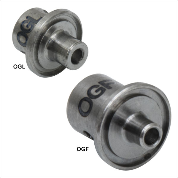
OGF
Ø2.5 mm Cannula Implant Guide
OGL
Ø1.25 mm Cannula Implant Guide
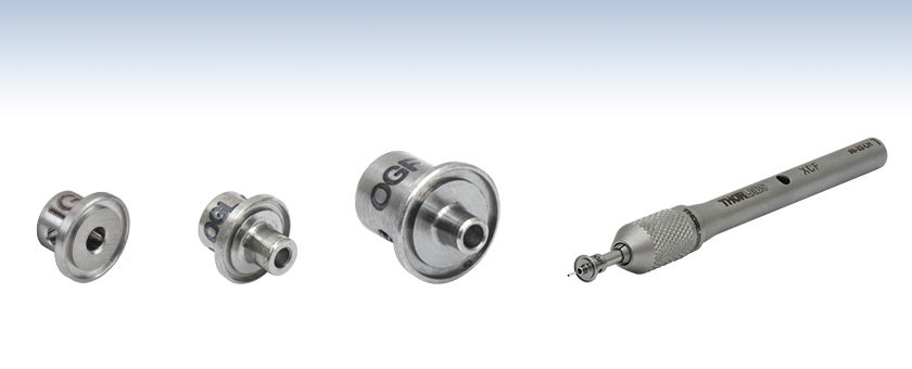
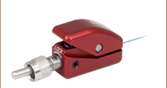
Application Idea
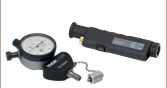
An OGF implant guide is used with an XCF cannula holder to hold a CFM22L05 cannula ferrule.
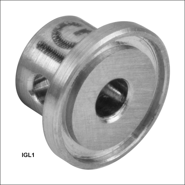
IGL1
Ø1.0 mm GRIN Lens Implant Guide


Please Wait
Click to Enlarge
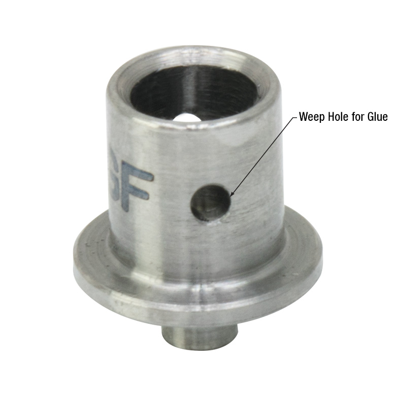
Figure 1.2 All implant guides feature at least one weep hole. The two weep holes of the OGF guide are shown here.
Click for Details
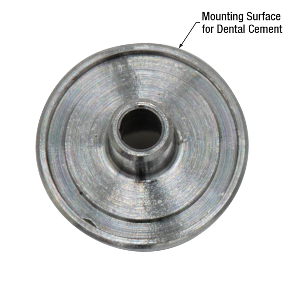
Figure 1.1 All implant guides feature a roughened, circular groove as shown with the OGF guide here.
| Selection Guide |
|---|
| GRIN Lenses |
| Fiber Optic Cannulae |
| Implant Guides for Stereotaxic Probes |
| Cannula Holders and Adapters |
Features
- Improves Adhesion and Stability During Implantation
- Lightweight Surgical Titanium Construction (≤0.11 g)
- Weep Holes for Glue and Epoxy to Secure Implanted Device
- Compatible with Stereotaxic Cannula Holders
Thorlabs offers implant guides designed to provide guidance and stability during an implant procedure to either our Ø1.0 mm GRIN lenses or our variety of fiber optic cannulae. The bottom surface of each implant guide features a roughened surface and circular groove that increases the surface area available for dental cement and improves adhesion to the specimen as shown in Figure 1.1. Each implant guide is constructed using lightweight surgical titanium (≤0.11 g) that can be sterilized prior to use. For convenience, the implant guides are offered below in packs of one or five.
For best results when implanting a GRIN lens or fiber optic cannula, the implant guide should be used with a cannula holder and stereotaxic guidance equipment. To affix the lens or cannula within the implant guide, first insert it into the through hole of the implant guide and position axially depending on its length and the type of application. Either one (Item # IGL1) or two (Item #’s OGL and OGF) Ø0.8 mm weep holes are featured in each implant guide to secure the lens or cannula with a small amount of cement or epoxy. Finally, secure the guide to an appropriate cannula holder.
| Posted Comments: | |
Fabio Mammano
(posted 2024-03-01 17:00:34.893) Can you please provide clear instruction on how OGL should be attached to a mouse skull using dental cement? Images of the preparation would be helpful. cdolbashian
(posted 2024-03-15 01:57:22.0) Thank you for reaching out to us with this inquiry Fabio. We unfortunately do not have an guide for this type of application. I have contacted you directly to inquire on further details, and perhaps find an alternate resource for you. dlindenbach
(posted 2017-02-27 14:08:22.35) The OGL and OGF cannula implant guides could be quite useful for me but they are fairly prohibitively expensive. I make my own fiber optic cannula using thorlabs materials because I can make a good cannula for 5 dollars instead of buying one for 60+ dollars. I need a good means of securing ceramic ferrules to the head, but I really can't be spending 15 dollars per ferrule on the implant. If you had a more affordable option, I would be all over it. Or if you have suggestions for making my own that would be very useful. For example, with metal guides, I can soulder a bit of thin wire to the cannula to make it "grip" the dental cement better. Thanks! tfrisch
(posted 2017-03-29 04:37:26.0) Hello, thank you for your interest in Thorlabs' products. I will reach out to you directly to discuss your application. |
| Quick Links | |||
|---|---|---|---|
| Single-Site Stimulation | |||
| One Light Source to One Cannula Implant | |||
| Multilateral Stimulation | |||
| One Light Source to Two Cannula Implants Using Rotary Joint Splitter | |||
| One or Two Light Sources to Two Cannula Implants | |||
| One Light Source to Seven Cannula Implants | |||
| Two Light Sources into One Dual-Core Cannula Implant | |||
| Illumination | |||
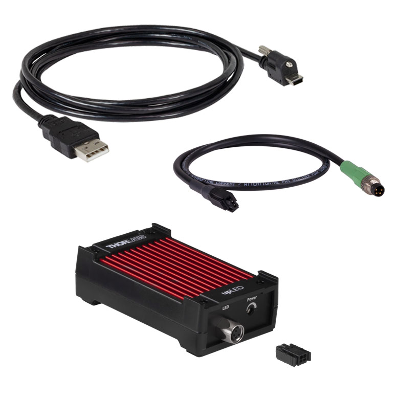
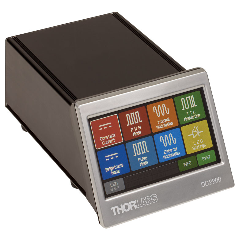
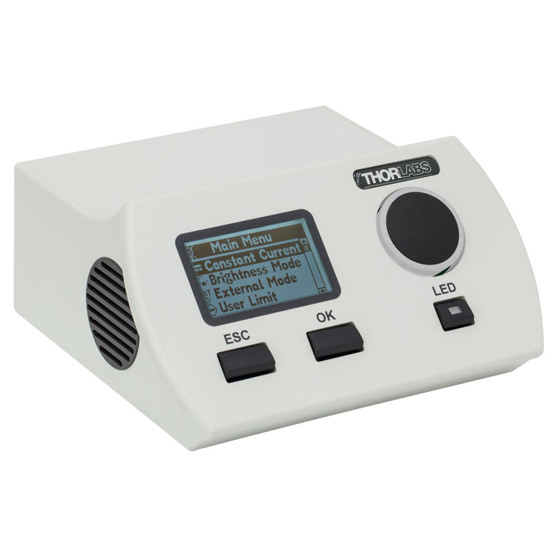
| Fiber-Coupled LEDs and Drivers | |||
Optogenetics Selection Guide
Thorlabs offers a wide range of optogenetics components; the compatibility of these products in select standard configurations is discussed in detail here. Please contact Technical Support for assistance with items outside the scope of this guide, including custom fiber components for optogenetics.
Single-Site Stimulation
One Light Source to One Cannula Implant
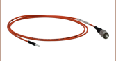
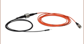
The most straightforward method for in vivo light stimulation of a specimen is to use a single fiber optic with a single LED light source. The single wavelength LED is powered by an LED driver, and then the illumination output is fiber-coupled into a patch cable, which connects to the implanted cannula. See the graphics and expandable compatibility tables below for the necessary patch cables and cannulae to create this setup. To choose the appropriate LED and driver, see below or the full web presentation.
Click on Each Component for More Information
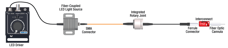

Click to See Ø1.25 mm (LC) Ferrule Compatible Patch Cables, Cannulae, and Interconnects
Click to See Ø2.5 mm (FC) Ferrule Compatible Patch Cables, Cannulae, and Interconnects
Multilateral Stimulation
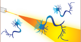
The ability to accurately and simultaneously direct light to multiple locations within a specimen is desired for many types of optogenetics experiments. For example, bilateral stimulation techniques typically target neurons in two spatially separated regions in order to induce a desired behavior. In more complex experiments involving the simultaneous inhibition and stimulation of neurons, delivering light of two different monochromatic wavelengths within close proximity enables the user to perform these experiments without implanting multiple cannulae, which can increase stress on the specimen.
Multilateral stimulation can be achieved with several different configurations depending on the application requirements. The sections below illustrate examples of different configurations using Thorlabs' optogenetics products.
Option 1: One Light Source to Two Cannula Implants Using Rotary Joint Splitter
Thorlabs' RJ2 1x2 Rotary Joint Splitter is designed for optogenetics applications and is used to split light from a single input evenly between two outputs. The rotary joint interface allows connected patch cables to freely rotate, reducing the risk of fiber damage caused by a moving specimen. See the graphic and compatibility table below for the necessary cables and cannulae to create this setup. For LEDs and drivers, see below or the full web presentation.
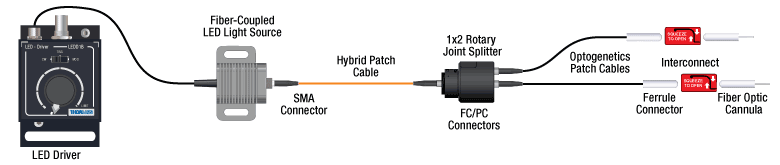
Click to See Ø1.25 mm (LC) Ferrule Components Recommended for Use with RJ2 Rotary Joint Splitter
Click to See Ø2.5 mm (FC) Ferrule Components Recommended for Use with RJ2 Rotary Joint Splitter
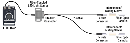
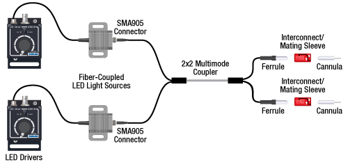
Option 2: One or Two Light Sources to Two Cannula Implants
If the intent is for one LED source to connect to two cannulae for simultaneous light modulation, then a bifurcated fiber bundle can be used to split the light from the LED into each respective cannula. For dual wavelength stimulation (mixing two wavelengths in a single cannula) or a more controlled split ratio between cannula, one can use a multimode coupler to connect one or two LEDs to the cannulae. If one cable end is left unused, the spare coupler cable end may be terminated by a light trap. See the graphic and compatibility table below for the necessary cables and cannulae to create this setup. For LEDs and drivers, see below or the full web presentation.
Click on Each Component Below for More Information
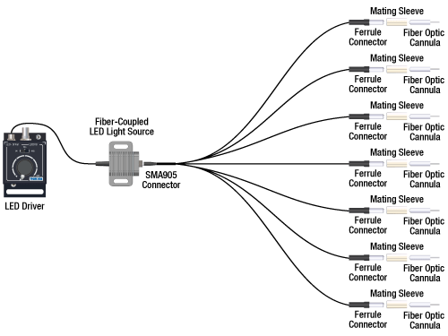
Option 3: One Light Sources to Seven Cannula Implants
If the intent is for one LED source to connect to seven cannulae for simultaneous light modulation, then a 1-to-7 fiber bundle can be used to split the light from the LED into each respective cannula. See the graphic and compatibility table below for the necessary cables and cannulae to create this setup. For LEDs and drivers, see below or the full web presentation.
Click on Each Component Below for More Information
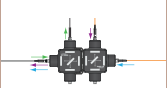
Two Light Sources into One Dual-Core Cannula Implant
For bilateral stimulation applications where the two cannulas need to be placed in close proximity (within ~1 mm), Thorlabs offers dual-core patch cables and cannulae that are designed for this specific application. Each core is driven by a separate light source, enabling users to stimulate and/or supress nerve cells in the same region of the specimen. See the graphic and compatibility table below for the necessary cables and cannulae to create this setup. For LEDs and drivers, see below or the full web presentation.
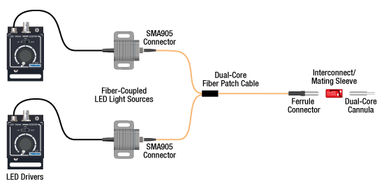
Click on Each Component for More Information
| Part Selection Table (Click Links for Item Description Popup) | |||||||||
|---|---|---|---|---|---|---|---|---|---|
| Common Fiber Properties | |||||||||
| Core Diameter | 200 µm | ||||||||
| Wavelength Range | 400 - 2200 nm | ||||||||
| NA | 0.39 | ||||||||
| Fiber Type | FT200EMT | ||||||||
| Ferrule Stylea | FC (Ø2.5 mm) | ||||||||
| Dual-Core Patch Cable | FC/PC Input | BFY32FL1 | |||||||
| SMA905 Input | BFY32SL1 | ||||||||
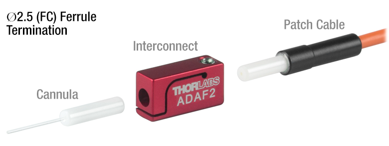
| Compatible Mating Sleeve/Interconnect | ADAF1 ADAF2 ADAF4-5 |
||||||||
| Dual-Core Fiber Optic Cannulaec | Stainless Steel | CFM32L10 CFM32L20 |
|||||||
| LED Item # | Wavelengtha | Typical Opsin | Output Powerb | Color |
|---|---|---|---|---|
| M405F3c | 405 nm | mmilCFP, hcriGFP | 3.7 mW | UV |
| M430F1 | 430 nm | ChR2 | 7.5 mW | Violet |
| M455F3 | 455 nm | ChIEF, bPAC | 24.5 mW | Royal Blue |
| M470F4 | 470 nm | ChR2, ChR2-SFO | 20 mW | Blue |
| M490F4 | 490 nm | Rh-CT, ChR2 (E123A) | 2.8 mW | Blue |
| M505F3 | 505 nm | ChRGR, Opto-α1AR, Opto-β2AR | 11.7 mW | Cyan |
| M530F3 | 530 nm | C1V1, VChR1 | 9.6 mW | Green |
| M565F3 | 565 nm | Arch, VChR1-SFO | 13.5 mW | Lime |
| M595F2 | 595 nm | ChR2-SFO, eNpHR3.0 | 11.5 mW | Amber |
| M625F2 | 625 nm | ReChR | 17.5 mW | Red |
Illumination
Click to Enlarge
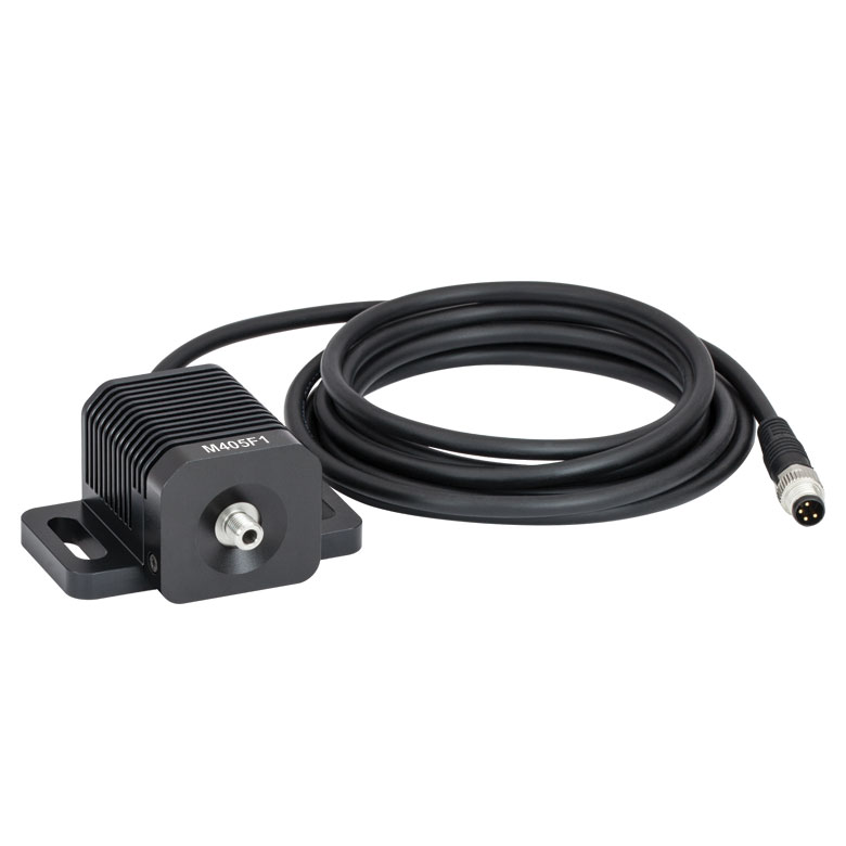
M405F1
Fiber-Coupled LEDs and Drivers
Our fiber-coupled LEDs are ideal light sources for optogenetics applications. They feature a variety of wavelength choices and a convenient interconnection to optogenetics patch cables. Thorlabs offers fiber-coupled LEDs with nominal wavelengths ranging from 280 nm to 1050 nm. See the table to the right for the LEDs with the most popular wavelengths for optogenetics. A table of compatible LED drivers can be viewed by clicking below.


 Zoom
Zoom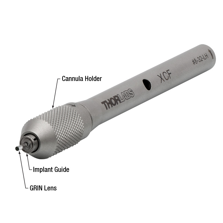
Click to Enlarge
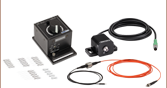
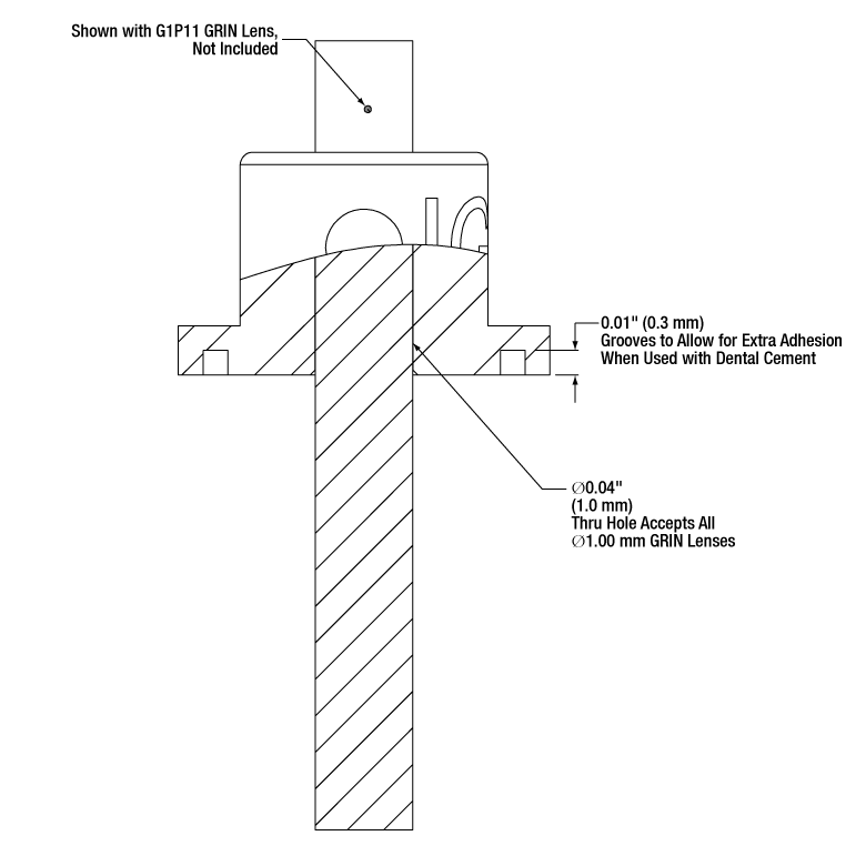
Figure G1.2 IGL1 Implant Guide with G1P11 GRIN Lens and XCF Cannula Holder (Not Included)
Click for Details
Figure G1.1 Cross Section Drawing of IGL1 Implant Guide with G1P11 GRIN Lens (Not Included)
- Compatible with Ø1 mm GRIN Lenses
- Ø3.8 mm Mounting Surface with Grooved Ring for Dental Cement
- Single Weep Hole for Glue or Epoxy to Secure a GRIN Lens
This Implant Guide is designed to provide guidance and stability for a Ø1 mm GRIN lens during an implantation procedure. The bottom surface of each implant guide features a circular groove that increases the surface area available for dental cement and improves adhesion to the specimen. Each implant guide is constructed using lightweight surgical titanium (0.06 g) that can be sterilized prior to use. For convenience, the implant guide is offered below in packs of one or five.
For best results when implanting a GRIN lens, the IGL1 implant guide should be used with a cannula holder and stereotaxic guidance equipment. To affix the GRIN lens within the implant guide, first insert the lens into the through hole of the implant guide and position axially depending on its length and the type of application (see Figure G1.1). Then, inject a small amount of cement or epoxy to the lens via the Ø0.8 mm weep hole. Finally, secure the guide to an XCF (Ø2.5 mm ferrule) cannula holder.

 Zoom
Zoom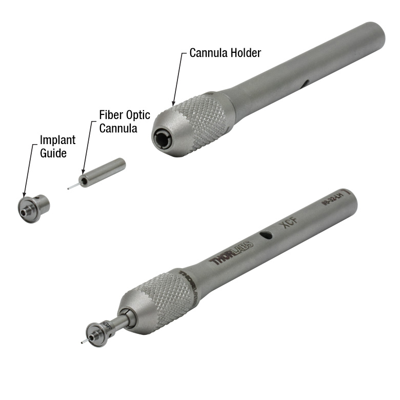
Click for Details
Figure G2.2 OGF Implant Guide with CFM22L05 Fiber Optic Cannula and XCF Cannula Holder (Not Included)
Click for Details
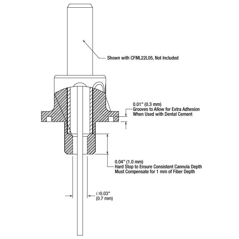
Figure G2.1 Cross Section Drawing of OGL with CFML22L05 Cannula (Not Included)
- Compatible with Ø1.25 mm or Ø2.5 mm Fiber Optic Cannulae with ≥5 mm Length
- Mounting Surface with Grooved Ring for Dental Cement
- Ø3.8 mm (Item # OGL)
- Ø5.1 mm (Item # OGF)
- Weep Holes for Glue and Epoxy to Secure a Cannula
These Cannula Implant Guides are designed to provide guidance and stability for a fiber optic cannula during an implantation procedure. The bottom surface of each implant guide features a roughened surface and circular groove that increases the surface area available for dental cement and improves adhesion to the specimen. A 1.6 mm long protrusion on the implant guide helps stabilize the guide when implanted. Each implant guide is constructed using lightweight surgical titanium (≤0.11 g) that can be sterilized prior to use. For convenience, the cannula guides are offered below in packs of one or five.
For best results when implanting a cannula, these implant guides should be used with a cannula holder and stereotaxic guidance equipment. To affix the cannula within the implant guide, first insert the cannula into the receptacle of the implant guide (see Figure G2.1). Then, add a small amount of cement or epoxy to the cannula via the two Ø0.8 mm weep holes. Finally, attach the implant guide with mounted ferrule to the appropriately sized cannula holder. The OGL implant guide is compatible with an XCL (Ø1.25 mm ferrule) and the OGF implant guide is compatible with and XCF (Ø2.5 mm ferrule) cannula holder.
The OGL implant guide is compatible with our standard Ø1.25 mm cannulae (ceramic and stainless steel) and the OGF implant guide is compatible with our standard Ø2.5 mm cannulae (ceramic and stainless steel). When assembled, the effective length of the protruding fiber is reduced by 1 mm (Item # OGL) or 2 mm (Item # OGF); therefore, these implant guides cannot be used with our 2 mm long cannulae. Additionally, due to the fiber separation distance, the implant guides cannot be used with our dual-core cannulae.