Birefringence Imaging System

- Measurements of Retardance and Azimuth (Fast Axis Orientation) in Flat Samples
- Stress- and Strain-Induced Birefringence Imaging
- Measure Ø20 mm Field of View in <20 s
- Additional Sample Mounting Accessories Available
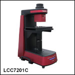
LCC7201C
Birefringence Imaging System
(Laptop Not Included)
Sample Measurement Results Using the
Birefringence Imaging System

Please Wait
Features
- Built-In 633 nm LED Light Source
- Measures Sample Retardance up to a Half-Wave (316 nm) and Azimuths up to ±90°
- Ø20 mm Field of View
- Included with the LCC7201C Birefringence Imaging System
- MLS203P2 Sample Holder
- Sample Holder Adapters for Ø1/2", Ø1", and 2" x 2" Optics
- Software (See Software Tab for Details)
- Optional Sample Mounting Accessories Offered Below
- MSB2328(/M) Breadboard
- MPSHA1 Slide Holder Insert or Recording Chamber Adapter
- MPSH2 and MPSH2SS Slide Holder Inserts
- MLS203-1 Fast XY Scanning Stage
- LPXY1 Low-Profile XY Scanning Stage
- Custom Operating Wavelengths by Contacting Tech Support
The LCC7201C Birefringence Imaging System measures stress- and strain-induced birefringence in flat samples for a variety of applications ranging from materials and biological research to product assurance (see the Applications tab for examples). This system is designed for use in academic research, medical diagnostics, industrial manufacturing, and product quality assurance. Since it is based on a liquid crystal device, there is no internal mechanical movement, leading to very stable, vibration-free operation.
The illumination wavelength of the standard imaging system is 633 nm. This wavelength can be customized from 488 nm to 780 nm by contacting Tech Support. The system provides a Ø20 mm field of view and measures retardance up to a half-wave (316 nm) and azimuths up to ±90°. The specifications of the LCC7201C system are outlined in the Specs tab.
A Windows®-based software package is included with the LCC7201C system that contains every feature needed for system control and data acquisition. To view additional information about this system's software features and sample measurement results, please refer to the Software tab.
For applications requiring imaging with higher spatial resolution, our CM50x Cerna® Birefringence Imaging Microscopes offer the same retardance and azimuth range and accuracy, with a 1.055 μm spatial resolution using the included 10X objective.
Sample Mounting Options
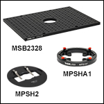
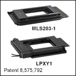
For sample viewing, the LCC7201C system includes Thorlabs' MLS203P2 Sample Holder. It also includes three sample holder adapters that are sized to hold Ø1/2”, Ø1”, and 2” x 2” optics. The MLS203P2 sample holder provides manual adjustment in the X direction, which is useful for samples larger than the Ø20 mm field of view. For sample rotation, the standard sample stage can be replaced with the MSB2328(/M) breadboard and MPSHA1 adapter. Additionally, larger samples can be scanned by upgrading the system with Thorlabs' MLS203-1 Fast XY Scanning Stage or LPXY1 Low-Profile XY Scanning Stage, which provide manual and motorized adjustment in both the X and Y directions. Examples of sample mounting options are shown in Figures 1.1, 1.2, and 1.3.

Click to Enlarge
Figure 1.3 LCC7201C Birefringence Imaging System with MLS203-1 Motorized Scanning Stage (not included) and included MLS203P2 Sample Holder.

Click to Enlarge
Figure 1.2 LCC7201C Birefringence Imaging System with MSB2328/M Aluminum Breadboard, MPSHA1 Slide Holder Insert Adapter, and MPSH2 Slide Holder Insert. Breadboard, adapter, and insert are not included with the imaging system.

Click to Enlarge
Figure 1.1 LCC7201C Birefringence Imaging System with Rigid Sample Stage and MLS203P2 Sample Holder. The stage and sample holder are included with the imaging system.
| LCC7201C Specifications | ||
|---|---|---|
| Light Source Wavelengtha | 633 nm | |
| Measurement Range | Retardance | Standard Retardance Range: 0 nm to 316 nm Low Retardance Range: 0 nm to 100 nm |
| Azimuth | ±90° | |
| Measurement Accuracy | Retardance | Standard Retardance Range: ±10 nm Low Retardance Range: ±1 nm |
| Azimuth | Standard Retardance Range: ±3° Low Retardance Range: ±1° |
|
| Measurement Rate | <20 s (Based on Default Camera Settings) | |
| Field of View | Ø20 mm | |
| Spatial Resolution | 9.77 μm | |
| Interfaces | USB 2.0 and USB 3.0 | |
| Imager Resolution | 2448 x 2048 Pixels | |
| Dimensions (D x W x H) | 500.0 mm x 360.0 mm x 672.0 mm | |
| Weight | 24.5 kg (54.0 lbs) | |
| Operating Temperature | 0 °C to 40 °C | |
| Storage Temperature | -15 °C to 65 °C | |
| Included Accessories | Sample Holder Adapters, Birefringent Resolution Target (Item # R3L1S1B) |
|
Software
Version 3.2.0
Click this button to visit the LCC7201x Birefringence Imaging System software page.
The LCC7201C system includes a Windows®-based software package that contains every feature needed for system control and data acquisition. Please click the Software button to download the latest software for this system.
Features
- Standard and Low Noise Modes for Retardance Measurements
- Selectable Rectangular or Circular Region of Interest (ROI)
- Adjustable Dynamic Camera Settings (Gain, Exposure Time, Black Levels)
- Overexposure Detection
- Auto Adjustment of Light Source Level
- 1D, 2D, and 3D Measurement Result Displays
- Data Output in Binary, CSV, and Image (PNG and TIFF) Formats
The LCC7201C software includes two modes, Standard Mode and Low-Noise Mode, to measure a sample's retardance. Standard Mode provides a higher measurement rate with a lower signal-to-noise ratio, while Low Noise Mode provides a lower measurement rate with a higher signal-to-noise ratio. An exposure time of 10 ms is set as the default, which allows a measurement to be finished within 20 seconds in Standard Mode and 4 minutes in Low Noise Mode.
These two modes provide two ranges of measurement accuracy: Standard Retardance Range and Low Retardance Range. Standard Retardance provides a measurement accuracy of ±10 nm for retardances in the 0 nm to 316 nm range and ±3° for azimuths over the entire measurement range. Low Retardance Range will improve the measurement accuracy to ±1 nm for retardances in the 0 nm to 100 nm range and ±1° for azimuths over the entire measurement range. The minimum exposure time is 0.021 ms, and the maximum exposure time is 7330 ms.
Figures 3.1 through 3.4 are screenshots from the included user interface, showing the different measurement display modes available. The Preview, 1D, 2D, and 3D views are all of a plastic ruler (stress-induced birefringence).

Click to Enlarge
Figure 3.2 1D View

Click to Enlarge
Figure 3.1 Camera Preview Showing Edge of Plastic Ruler

Click to Enlarge
Figure 3.4 Azimuth 3D View

Click to Enlarge
Figure 3.3 Retardance with Azimuth Vector 2D View
Application Image Gallery
Thorlabs’ LCC7201C Birefringence Imaging System is a powerful tool to understand the birefringent properties of many materials. It provides quick and easy birefringence measurements, which can be applied to research in fields such as industrial manufacturing, biology, and medicine. Click on the tabs to see some applications of this birefringence imaging system.
Verification of Laser-Induced Birefringence Change in a Polymer Wave Plate
Azimuth and Retardance Change of a Polymer Wave Plate with Different Laser Fluences
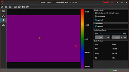
When a quartz or liquid crystal polymer wave plate is integrated into a system for a given application, the laser induced birefringence change, i.e., retardance and fast axis orientation (azimuth), can be critical. Since even a very slight change can create problems in practical applications, the verification of such changes is essential. Typically, these changes are not easily measured by a polarizing microscope, but our LCC7201C Birefringence Imaging System is sensitive to retardance and azimuth changes as small as ±1 nm and ±1° (Low Retardance Range). The example measurement results shown in Figures 4.1 through 4.4 for a Thorlabs' Liquid Crystal Polymer Zero-Order Half-Wave Plate (Item # WPH10E-830) indicate retardance and azimuth changes in two regions due to laser-induced damage threshold (LIDT) testing. The central spot experienced the larger laser fluence and shows a larger area of retardance and azimuth changes, while the smaller spot on the right edge was exposed to a smaller laser fluence.

Click to Enlarge
Figure 4.2 Azimuth 2D View

Click to Enlarge
Figure 4.1 Preview View

Click to Enlarge
Figure 4.4 Retardance 3D View

Click to Enlarge
Figure 4.3 Retardance 2D View
Analysis of Stress- and Strain-Induced Birefringence for Materials Research: Plastic Ruler
Azimuth and Retardance Distribution of a Plastic Ruler
Transparent isotropic materials, e.g., fused silica, float and fusion glass, and many plastics, have uniform refractive index in all directions and do not exhibit birefringence. However, mechanical stress can cause birefringence in these materials. The stress can be temporarily caused by external forces or be a permanent change after manufacturing processes. Some examples are plastic that was manufactured using injection molding, laser crystals produced by poor opto-mechanical mounting and packaging techniques, glass to metal bonding using ultrashort laser pulse welding, and hydroxide catalysis bonding. Also, optically transparent materials can undergo strain at the molecular level due to various environmental conditions, such as external pressures, vibration, or temperature change.
The stress- and strain-induced birefringence in transparent optical materials alters the polarization state (for both linear and elliptical polarization) and affects the wavefront of a transmitted optical beam. An easy way to analyze this birefringence would be to place the sample between two crossed polarizers. In addition, a polarizing microscope or a polarization camera could be used as an alternative method. However, the crossed polarizers and polarization camera verify the stress- and strain-induced birefringence that affects linear polarization only, and the polarization microscope requires manual fine phase compensation for the detection of elliptical polarization, which can be time-consuming. The LCC7201C Birefringence Imaging System provides a faster and more complete analysis, including the effect on elliptical polarization.
Figures 4.5 through 4.10 shows the measurement results of the stress distribution of an injection molded plastic ruler.

Click to Enlarge
Figure 4.6 1D View

Click to Enlarge
Figure 4.5 Preview View

Click to Enlarge
Figure 4.8 Azimuth 2D View

Click to Enlarge
Figure 4.7 Retardance with Azimuth Vector 2D View

Click to Enlarge
Figure 4.10 Retardance 3D View

Click to Enlarge
Figure 4.9 Retardance 2D View
Analysis of Fiber Birefringence: Bent Optical Fiber
Azimuth and Retardance Distribution of a Bent Optical Fiber
Single mode fibers support two modes simultaneously, which are orthogonally polarized. In an ideal circular-core fiber, made from homogenous isotropic materials, these two modes will propagate with the same phase velocity and will exhibit the same refractive index. However, in practice, most single mode fibers are not perfectly circularly symmetric (noncircular core), and the two modes propagate with different phase and group velocities. Also, the fiber exhibits anisotropy due to bending, twisting, or other mechanical stresses that are accidentally introduced in the manufacturing process. So the fiber will behave as a birefringent medium with different refractive indices and phase velocities. As a consequence, the fiber birefringence changes the output SOP (State of Polarization), which in turn creates problems in many practical applications, such as fiber optic interferometer sensors, coupling between optical fibers and integrated optic devices, and coherent communication systems. The LCC7201C Birefringence Imaging System can be used as a powerful tool not only for the determination of birefringence in optical fiber but also for the verification of a fiber birefringence suppression method. As an example, a single mode fiber (Corning® SMF-28e+®*) was bent with different bending radii and imaged with an LCC7201C system; the results are shown in Figures 4.11 through 4.14. The upper optical fiber (upper black line in Figure 4.11) has a smaller bending radius than the lower optical fiber, and the retardance difference between the different bending radii is confirmed in Figures 4.11 through 4.14.
*SMF-28e+® is a registered trademark of Corning.

Click to Enlarge
Figure 4.12 1D View

Click to Enlarge
Figure 4.11 Preview View

Click to Enlarge
Figure 4.14 Azimuth 2D View

Click to Enlarge
Figure 4.13 Retardance 2D View
Visualize Cell Birefringence for Cell Behavior Analysis or Cell Screening: Natural Plant Fiber
Azimuth and Retardance Distribution of a Natural Plant Fiber Whole Mount (w.m.) (Complete Organism)
Natural plant fiber structures, e.g., cotton fiber, show large retardance due to high levels of cellulosic material in the fiber’s secondary cell wall, which is directionally aligned with the fibers. The LCC7201C system allows for the visualization of birefringence in natural plant fibers.

Click to Enlarge
Figure 4.16 Azimuth 2D View

Click to Enlarge
Figure 4.15 Preview View

Click to Enlarge
Figure 4.18 Retardance 3D View

Click to Enlarge
Figure 4.17 Retardance 2D View
Visualize Cell Birefringence for Cell Behavior Analysis or Cell Screening: Human Hair Follicle Section
Azimuth and Retardance Distribution of a Human Hair Follicle Section
The human hair follicle is birefringent due to crystalline structures corresponding to dermal collagen in the dermal layer. The LCC7201C system allows the user to study molecular-structure-induced birefringence of collagen and reticulin. In contrast to a polarizing microscope, this birefringence imaging system does not require rotating the polarizer or fine changes of the waveplate for phase compensation. Some example data is shown in Figures 4.19 through 4.22.

Click to Enlarge
Figure 4.20 Azimuth 2D View

Click to Enlarge
Figure 4.19 Preview View

Click to Enlarge
Figure 4.22 Retardance 3D View

Click to Enlarge
Figure 4.21 Retardance 2D View
Fast-Axis Distribution Inspection of a Liquid Crystal Polymer Patterned Retarder: m = 4 Vortex Retarder
Azimuth and Retardance Distribution of m = 4 Zero-Order Vortex Half-Wave Plate
Thorlabs' Vortex Retarders are manufactured using photo alignment technology that can write a pattern of fast axes at any angle within a resolution of <1°. These patterned retarders are used in 3D displays, polarization imaging, and diffractive optical applications, e.g., polarization gratings, polarimetry, and beam steering. One simple method to verify or inspect the fast axis distribution of a patterned retarder is to check the intensity profile using two crossed polarizers. However, this method usually requires half-wave retardance for better contrast and cannot precisely indicate the fast axis orientation. Instead, the LCC7201C system offers a precise and quick measurement of fast axis orientation regardless of the retardance of the patterned retarder. Therefore, it is a powerful tool for both research and industrial fields. An example of a custom, m = 4, zero-order vortex half-wave plate is shown in Figures 4.23 through 4.26. More examples of these types of measurements, for a WPV10-532 m = 2 vortex retarder, are shown in the Software tab.

Click to Enlarge
Figure 4.24 Retardance with Azimuth Vector 2D View

Click to Enlarge
Figure 4.23 Preview View

Click to Enlarge
Figure 4.26 Azimuth 3D View

Click to Enlarge
Figure 4.25 Azimuth 2D View

Click to Enlarge
Figure 5.1 LCC7201C Components (Not Shown to Scale)
LCC7201C Birefringence Imaging Microscope Shipping List
Item # LCC7201C consists of:
- Main LCC7201C Body
- Birefringent 1951 USAF Test Target (Item # R3L1S1B)
- 12 VDC Power Supply (Item # DS12)
- Region-Specific Power Cord, 2 m Long
- USB 2.0 Type-A to Type-B Cable, 2 m Long
- USB 3.0 Type-A to Micro B Cable, 2 m Long
- Sample Holder Adapters for Ø1/2", Ø1", and 2" x 2" Optics
- Manual (Not Shown)
Birefringence Imaging System Publications
2022
Sergey I. Kudryashov, Pavel A. Danilov, Alexey E. Rupasov, Mikhail P. Smayev, Nikita A. Smirnov, Vladimir V. Kesaev, Andrey N. Putilin, Michael S. Kovalev, Roman A. Zakoldaev, and Sergey A. Gonchukov, "Direct laser writing regimes for bulk inscription of polarization-based spectral microfilters and fabrication of microfluidic bio/chemosensor in bulk fused silica," Laser Physics Letters 19, no. 6 (2022): 065602.
2021
Megan Lynn Morgan, Craig Brideau, Wulin Teo, Andrew Vincent Caprariello, Peter K. Stys, "Label-free assessment of myelin status using birefringence microscopy," Journal of Neuroscience Methods, Volume 360, p. 109226 (2021).
| Posted Comments: | |
Wang Lin
(posted 2024-10-17 08:39:11.23) hello!
what is [Low Retardance Range] and [Standard Retardance Range] means?
If I test a 633 HWP(Half Wave Plate),then I can get [633/2 ±10nm] or [633/2±1nm]? Which is right?
你好!
请问[Low Retardance Range]和[Standard Retardance Range]分别是什么意思?
比如说,我测量633半波片,我会得到什么结果?是633半波±10nm,还是±1nm? jdelia
(posted 2024-10-22 04:00:09.0) Thank you for contacting Thorlabs. The LCC7201B software provides two ranges of measurement accuracy: Standard Retardance Range and Low Retardance Range. Standard Retardance provides a measurement accuracy of ±10 nm for retardances in the 0 nm to 316 nm range and ±3° for azimuths over the entire measurement range. Low Retardance Range will improve the measurement accuracy to ±1 nm for retardances in the 0 nm to 100 nm range and ±1° for azimuths over the entire measurement range. While measuring the retardance of 633 nm half waveplate, the results in these two ranges shall all within 316.5nm+0/-10nm. If the sample retardance is less than 100 nm, using Low Retardance Range will typically obtain the retardance accuracy of ±1 nm.
感谢联系Thorlabs!LCC7201B软件提供了两种测量精确度范围:标准延迟范围和低延迟范围。标准延迟在0到316 nm的范围内提供±10 nm延迟测量精度,在整个测量范围内提供±3°方位角测量精度。低延迟在0到100 nm的范围内提供±1 nm延迟测量精度,在整个测量范围内提供±1°方位角测量精度。当测量633nm半波片的延迟时,这两种测量范围内的结果都在316.5nm+0/-10nm范围内。如果样品的延迟小于100 nm时,使用低延迟范围通常会获得±1 nm的延迟精度。 |


Click to Enlarge
Figure G1.1 The back panel of the LCC7201C provides USB 2.0 Type-B and USB 3.0 Micro B ports for connecting the system to a PC, a service switch, a power supply input, and a power switch.
- Built-In 633 nm LED Light Source
- Measures Sample Retardance up to a Half-Wave (316 nm) and Azimuths up to ±90°
- Ø20 mm Field of View
- Windows®-Based Software Package Included (See Software Tab for Details)
- Included Sample Holders
- MLS203P2 Sample Holder
- Sample Holder Adapters for Ø1/2", Ø1", and 2" x 2" Optics
The LCC7201C Birefringence Imaging System measures stress- and strain-induced birefringence in flat samples for a variety of applications ranging from materials and biological research to product assurance (see the Applications tab for examples).
The system includes a rigid stage and adapters to hold Ø1/2", Ø1", and 2" x 2" samples. For a wider variety of sample shapes and applications requiring motorized scanning or rotation, additional accessories are available below.
In addition to the sample holder adapters, the LCC7201C system comes with a DS12 12 VDC power supply, region-specific power cord, Manual, USB 2.0 Type-A to Type-B Cable, USB 3.0 Type-A to Micro B Cable and a R3L1S1B Birefringent 1951 USAF Test Target. A Windows®-based computer (not included) is required for operation.

- Breadboards Provide Flexible Mounting Platform
- Adapter for Holding Recording Chambers and Slide Holder Inserts
- Slide Holder Insert for Holding Microscope Slides
For samples requiring rotation or greater flexbility in mounting, the MSB2328(/M) Aluminum Breadboards, MPSHA1 Slide Holder Insert and Recording Chamber Adapter, and aluminum (Item # MPSH2) or stainless steel (Item # MPSH2SS) Slide Holder Inserts are available for use with the LCC7201C birefringence imaging system.
The MSB2328(/M) breadboards have four M5 counterbored mounting holes positioned to allow the breadboards to be mounted in the LCC7201C system. The 1.97" (50.0 mm) central aperture of the breadboards is aligned with the optical axis of the imaging system.
The MPSHA1 adapter is designed for convenient mounting of a recording chamber in the optical path of an LCC7201C system with an integrated MSB2328(/M) breadboard. The adapter can be attached to the breadboard with four 1/4"-20 (M6) screws. The top platform has a Ø110 mm opening with a 5 mm wide lip and four clamps to securely mount a recording chamber in the optical path. Alternatively, the MPSH2 and MPSH2SS slide holder inserts are available for mounting a microscope slide (up to 26.0 mm x 76.2 mm). The MPSH2 insert has a non-magnetic aluminum base plate while the MPSH2SS insert is stainless steel, which is ideal in setups where a magnetic surface is needed.
For custom plate inserts, please contact Tech Support.
| Breadboard Specifications | |||||||||
|---|---|---|---|---|---|---|---|---|---|
| Item # | Top Surface Dimensions | Breadboard Thickness | Central Aperture Diameter | Hole Threading and Spacing | Distance from Edge to First Hole | Number of Counterbored Holes | Material | Finish | Flatness |
| MSB2328 | 9.06" x 11.02" | 0.37" | 1.97" | 8-32 Taps with 1/2" Spacing and 1/4"-20 Taps with 1" Spacinga | 0.51" from the Short Edges and 0.53" from the Long Edges | Four M5b | Aluminum Plate | Matte Black Anodized | ±0.010" (0.25 mm) over Entire Surface |
| MSB2328/M | 230 mm x 280 mm |
9.5 mm | 50.0 mm | M4 Taps with 12.5 mm Spacing and M6 Taps with 25 mm Spacinga | 15 mm on All Sides | Four M5b | Aluminum Plate | Matte Black Anodized | ±0.010" (0.25 mm) over Entire Surface |

| Key Specifications | ||
|---|---|---|
| Item # | MLS203-1 | LPXY1 |
| Travel Range | 110 mm x 75 mm (4.3" x 2.95") | |
| Velocity (Max) | 250 mm/s | 25 mm/s |
| Acceleration (Max) | 2000 mm/s2 | 400 mm/s2 |
| Bidirectional Repeatability | 0.25 µm | <±2.5 µm |
| Unidirectional Repeatability | 0.25 µm | <±2.5 µm |
| Horizontal Load Capacity (Max)a | 1 kg (2.2 lb) | |
| Min Achievable Incremental Movement | 0.1 µm | |
| Home Location Accuracy | 0.25 µm | <±2.5 µm |
| On-Axis Accuracy | <3 µmc | <±5.0 µmb |
| Dimensions (Mid Travel, Excluding Guards) | 260.0 mm x 230.0 mm x 31.3 mm (10.24" x 9.06" x 1.23") |
310.1 mm x 255.6 mm x 32.3 mm (12.21" x 10.06" x 1.27") |
The MLS203-1 and LPXY1 XY scanning stages can be used as drop-in replacements for the manual stage found on the LCC7201C system and provide motorized XY positioning of microscopy samples. We also offer a range of slide holders to allow the positioning of standard microscope slides, multiwell plates, petri dishes, and mounted metallurgical specimens.
The recommended controller for the MLS203 stage is the BBD302 dual-axis Brushless DC Motor Controller. A Kinesis® GUI interface ships with each controller. The stage is also compatible with µManager, which is open-source software for controlling microscopes and peripherals, and Molecular Devices' MetaMorph, which is software that provides automated acquisition, control, and image analysis. The recommended controller for the LPXY1 scanning stage is the BSC202 Two-Channel Benchtop Stepper Motor Controller, which features Thorlabs' Kinesis control and programming interface.
For more details on the MLS203-1 or LPXY1 scanning stage and their corresponding accessories, please see the full presentation for our high-speed motorized XY scanning stages and low-profile motorized XY scanning stages, respectively.
 Products Home


 Zoom
Zoom

 Birefringence Imaging System