SM1-Compatible Manual Rotation Mounts
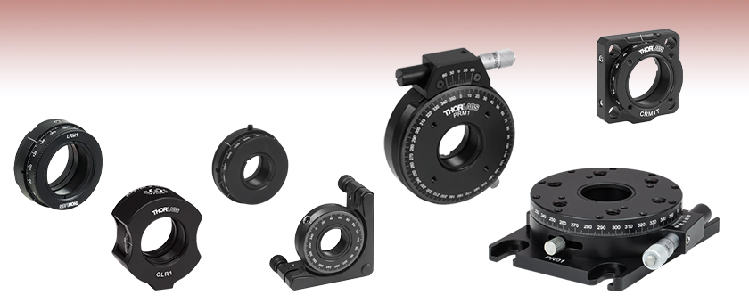
- Mount Ø1/2" (Ø12.7 mm) Optics, Ø1" (Ø25.4 mm) Optics, or SM1 (Ø1.035"-40) Lens Tubes
- 360° Continuous Rotation
CRM05
Internal SM05 Threads,
External SM1 Threads
CLR1
Rotation Mount for Ø1" Optics and Two SM1 Lens Tubes
PRM1
High-Precision Rotation Mount for Ø1" Optics
CRM1T
Cage System Rotation Mount for Ø1" Optics
PR01
High-Precision Rotation Platform
LRM1
Internal and External SM1 Threads
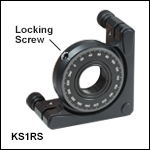
KS1RS
Ø1" Kinematic Rotation Mount

Please Wait
Features
- Rotation Mounts with Internal or External SM1 (1.035"-40) Threads
- Compatible with SM1-Threaded Components
- Engraved Scale
This page has a compilation of rotation mounts that feature internal or external SM1 (1.035"-40) threads and can mount Ø1/2" (Ø12.7 mm) optics, Ø1" (Ø25.4 mm) optics, or SM1-threaded components. Each mount allows for 360° rotation of an optic, SM1-threaded component, or platform.
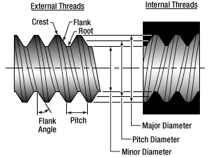
Thorlabs introduced the SM Thread Standards to ensure compatibility over a broad range of product lines. SM-threaded components offer a simple and efficient solution for building optomechanical structures. Our SM-threaded products, including lens tubes and cage system components, fixed and kinematic mounts, irises and diaphragms, provide flexibility when constructing complex optical systems. Please see the Threading Specs tab for more information on Thorlabs' SM thread standards.
Thorlabs also has similar compilations of SM-threaded rotation mounts for Ø1/2" (Ø12.7 mm) and Ø2" (Ø50.8 mm) optics. For our entire selection of rotation mounts, please see the Rotation Mounts and Stages tab.
Reading a Vernier Scale on a Linear Main Scale
Vernier scales are typically used to add precision to standard, evenly divided scales (such as the scales on Thorlabs' rotation, goniometric, or translation mounts). A vernier scale has found common use in many precision measurement instruments, the most common being calipers and micrometers. The vernier scale uses two scales side-by-side: the main scale and the vernier scale. The direct vernier scale has a slightly smaller spacing between its tick marks owing to the vernier scale having N ticks for every N - 1 ticks on the main scale. Hence, the lines on the main scale will not line up with all the lines on the vernier scale. Only one line from the vernier scale will match well with one line of the main scale, and that is the trick to reading a vernier scale.
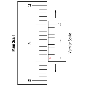
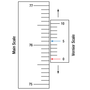
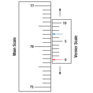
Figures 130A through 130C show a linear vernier scale system for three different situations. In each case, the scale on the left is the main scale, while the small scale on the right is the vernier scale. When reading a vernier scale, the main scale is used for the gross number, and the vernier scale gives the precision value. In this manner, a standard ruler or micrometer can become a precision instrument.
The 0 on the vernier scale is the "pointer" (marked by a red arrow in Figures 130A through 130E) and will indicate the main scale reading. In Figure 130A we see the pointer is lined up directly with the 75.6 line. Notice that the only other vernier scale tick mark that lines up well with the main scale is 10. Since the pointer lines up with the main scale’s 75.6, the reading from Figure 130A is 75.60 (in whatever units the instrument measures).
That is essentially all there is to reading a vernier scale. It's a very straightforward way of increasing the precision of a measurement instrument. To expound, let’s look at Figure 130B. Here we see that the pointer is no longer aligned with a line on the main scale, but instead it is slightly above 75.6 and below 75.7; thus, the gross measurement is 75.6. The first vernier line that coincides with a main scale line is the 5, shown with a blue arrow. The vernier scale gives the final digit of precision; since the 5 is aligned to the main scale, the precision measurement for Figure 130B is 75.65.
Since this vernier scale is 10% smaller than the main scale, moving the vernier scale by 1/10 of the main scale will align the next vernier marking. This asks the obvious question: what if the measurement is within the 1/10 precision of the vernier scale? Figure 130C shows just this. Again, the pointer line is in between 75.6 and 75.7, yielding the gross measurement of 75.6. If we look closely, we see that the vernier scale 7 (marked with a blue arrow) is very closely aligned to the main scale, giving a precision measurement of 75.67. However, the vernier scale 7 is very slightly above the main scale mark, and we can see that the vernier scale 8 (directly above 7) is slightly below its corresponding main scale mark. Hence, the scale on Figure 130C could be read as 75.673 ± 0.002. A reading error of about 0.002 would be appropriate for
this instrument.
Click to Enlarge
Figure 130A An example of how to read a vernier scale. The red arrow indicates what is known as the pointer. Since the tick mark labeled 10 on the vernier scale aligns with one of the tick marks on the main scale, this vernier scale is reading 75.60 (in whatever units the instrument measures).
Click to Enlarge
Figure 130B The red arrow indicates the pointer and the blue arrow indicates the vernier line that matches the main scale. This scale reads 75.65.
Click to Enlarge
Figure 130C The red arrow indicates the pointer, and the blue arrow indicates the vernier line that matches the main scale. This scale reads 75.67 but can be accurately read as
75.673 ± 0.002.
Reading a Vernier Scale on a Rotating Main Scale
The vernier scale may also be used on rotating scales where the main scale and vernier scale do not share units. Figures 130D and 130F show a vernier scale system for two different situations where the main scale is given in degrees and the vernier scale has ticks every 5 arcmin (60 arcmin = 1°). In each case, the scale on the top is the main scale, while the small scale on the bottom is the vernier scale.
In Figure 130D we see the pointer is lined up directly with the 341° line. Notice that the only other vernier scale tick marks that line up well with the main scale are ±60 arcmin. Since the pointer lines up with the main scale at 341°, the reading from Figure 130D is 341.00°.
There are two ways to determine the reading if the zero on the vernier scale line is between two lines of the main scale. For the first method, take the line on the left side of the pointer on the vernier scale and subtract that value (in arcmin) from the value on the main scale that is to the right on the main scale. As an example, in Figure 130E the vernier pointer is between 342° and 343°; using the left blue arrow of the vernier scale results in
As we've seen here, vernier scales add precision to a standard scale measurement. While it takes a bit of getting used to, with a little practice, reading these scales is fairly straightforward. Vernier scales, whether they are direct or retrograde*, are read in the same fashion.
*A retrograde vernier scale has a larger spacing between its tick marks with N ticks for every N + 1 ticks on the main scale.
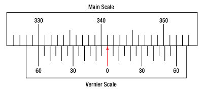
Click to Enlarge
Figure 130D An example of a vernier scale where the main scale and the vernier scale are in different units (degrees and arcmins, respectively). The red arrow indicates the pointer. This scale reads 341.00°.
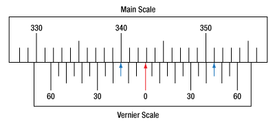
Click to Enlarge
Figure 130E The red arrow indicates the pointer and the blue arrows give the precision value from the vernier scale.
This scale reads 342.75°.
| SM05 Threading: Ø1/2" Lens Tubes, 16 mm Cage Systems | |||
|---|---|---|---|
| External Thread, 0.535"-40.0 UNS-2A | Internal Thread, 0.535"-40.0 UNS-2B | ||
| Max Major Diameter | 0.5340" | Min Major Diameter | 0.5350" |
| Min Major Diameter | 0.5289" | Min Pitch Diameter | 0.5188" |
| Max Pitch Diameter | 0.5178" | Max Pitch Diameter | 0.5230" |
| Min Pitch Diameter | 0.5146" | Min Minor Diameter (and 83.3% of Thread) | 0.508" |
| Max Minor Diameter | 0.5069" | Max Minor Diameter (and 64.9% of Thread) | 0.514" |
| RMS Threading: Objective, Scan, and Tube Lenses | |||
|---|---|---|---|
| External Thread, 0.800"-36.0 UNS-2A | Internal Thread, 0.800"-36.0 UNS-2B | ||
| Max Major Diameter | 0.7989" | Min Major Diameter | 0.8000" |
| Min Major Diameter | 0.7934" | Min Pitch Diameter | 0.7820" |
| Max Pitch Diameter | 0.7809" | Max Pitch Diameter | 0.7866" |
| Min Pitch Diameter | 0.7774" | Min Minor Diameter (and 83.3% of Thread) | 0.770" |
| Max Minor Diameter | 0.7688" | Max Minor Diameter (and 64.9% of Thread) | 0.777" |
| C-Mount Threading: Machine Vision Lenses, CCD/CMOS Cameras | |||
|---|---|---|---|
| External Thread, 1.000"-32.0 UN-2A | Internal Thread, 1.000"-32.0 UN-2B | ||
| Max Major Diameter | 0.9989" | Min Major Diameter | 1.0000" |
| Min Major Diameter | 0.9929" | Min Pitch Diameter | 0.9797" |
| Max Pitch Diameter | 0.9786" | Max Pitch Diameter | 0.9846" |
| Min Pitch Diameter | 0.9748" | Min Minor Diameter (and 83.3% of Thread) | 0.966" |
| Max Minor Diameter | 0.9651" | Max Minor Diameter (and 64.9% of Thread) | 0.974" |
| SM1 Threading: Ø1" Lens Tubes, 30 mm Cage Systems | |||
|---|---|---|---|
| External Thread, 1.035"-40.0 UNS-2A | Internal Thread, 1.035"-40.0 UNS-2B | ||
| Max Major Diameter | 1.0339" | Min Major Diameter | 1.0350" |
| Min Major Diameter | 1.0288" | Min Pitch Diameter | 1.0188" |
| Max Pitch Diameter | 1.0177" | Max Pitch Diameter | 1.0234" |
| Min Pitch Diameter | 1.0142" | Min Minor Diameter (and 83.3% of Thread) | 1.008" |
| Max Minor Diameter | 1.0068" | Max Minor Diameter (and 64.9% of Thread) | 1.014" |
| SM30 Threading: Ø30 mm Lens Tubes | |||
|---|---|---|---|
| External Thread, M30.5 x 0.5 – 6H/6g | Internal Thread, M30.5 x 0.5 – 6H/6g | ||
| Max Major Diameter | 30.480 mm | Min Major Diameter | 30.500 mm |
| Min Major Diameter | 30.371 mm | Min Pitch Diameter | 30.175 mm |
| Max Pitch Diameter | 30.155 mm | Max Pitch Diameter | 30.302 mm |
| Min Pitch Diameter | 30.059 mm | Min Minor Diameter (and 83.3% of Thread) | 29.959 mm |
| Max Minor Diameter | 29.938 mm | Max Minor Diameter (and 64.9% of Thread) | 30.094 mm |
| SM1.5 Threading: Ø1.5" Lens Tubes | |||
|---|---|---|---|
| External Thread, 1.535"-40 UNS-2A | Internal Thread, 1.535"-40 UNS-2B | ||
| Max Major Diameter | 1.5339" | Min Major Diameter | 1.535" |
| Min Major Diameter | 1.5288" | Min Pitch Diameter | 1.5188" |
| Max Pitch Diameter | 1.5177" | Max Pitch Diameter | 1.5236" |
| Min Pitch Diameter | 1.5140" | Min Minor Diameter (and 83.3% of Thread) | 1.508" |
| Max Minor Diameter | 1.5068" | Max Minor Diameter (and 64.9% of Thread) | 1.514" |
| SM2 Threading: Ø2" Lens Tubes, 60 mm Cage Systems | |||
|---|---|---|---|
| External Thread, 2.035"-40.0 UNS-2A | Internal Thread, 2.035"-40.0 UNS-2B | ||
| Max Major Diameter | 2.0338" | Min Major Diameter | 2.0350" |
| Min Major Diameter | 2.0287" | Min Pitch Diameter | 2.0188" |
| Max Pitch Diameter | 2.0176" | Max Pitch Diameter | 2.0239" |
| Min Pitch Diameter | 2.0137" | Min Minor Diameter (and 83.3% of Thread) | 2.008" |
| Max Minor Diameter | 2.0067" | Max Minor Diameter (and 64.9% of Thread) | 2.014" |
| SM3 Threading: Ø3" Lens Tubes | |||
|---|---|---|---|
| External Thread, 3.035"-40.0 UNS-2A | Internal Thread, 3.035"-40.0 UNS-2B | ||
| Max Major Diameter | 3.0337" | Min Major Diameter | 3.0350" |
| Min Major Diameter | 3.0286" | Min Pitch Diameter | 3.0188" |
| Max Pitch Diameter | 3.0175" | Max Pitch Diameter | 3.0242" |
| Min Pitch Diameter | 3.0133" | Min Minor Diameter (and 83.3% of Thread) | 3.008" |
| Max Minor Diameter | 3.0066" | Max Minor Diameter (and 64.9% of Thread) | 3.014" |
| SM4 Threading: Ø4" Lens Tubes | |||
|---|---|---|---|
| External Thread, 4.035"-40 UNS-2A | Internal Thread, 4.035"-40.0 UNS-2B | ||
| Max Major Diameter | 4.0337" | Min Major Diameter | 4.0350" |
| Min Major Diameter | 4.0286" | Min Pitch Diameter | 4.0188" |
| Max Pitch Diameter | 4.0175" | Max Pitch Diameter | 4.0245" |
| Min Pitch Diameter | 4.0131" | Min Minor Diameter (and 83.3% of Thread) | 4.008" |
| Max Minor Diameter | 4.0066" | Max Minor Diameter (and 64.9% of Thread) | 4.014" |
| Posted Comments: | |
user
(posted 2016-04-06 16:33:44.513) on the CLR1 continuous rotation mount it is really annoying that when screwing something into either side of the rotation mount, if the thread is longer than usually found on sm1 tubes (e.g. on adaptors and couplers) you can end up screwing right in to hit the rotating part of the mount, locking it in position, meaning you have to use a locking nut to limit the depth you screw into. I don't understand why the thread is all the way through to allow this to happen, I can't think of one possible scenario where this is at all useful, and it is so easy to prevent. besembeson
(posted 2016-04-06 11:09:20.0) Response from Bweh at Thorlabs USA: Thanks for pointing this out. As you correctly realized, the original design was to accommodate our standard lens tubes that have the 3mm threaded coupling segment. When using lens tubes with longer threaded segment, the retaining ring that ships with the unit prevents this during back mounting. There is not enough room to do same in the front mount. We will review the design in light of your comments and add notes to our web page. jlow
(posted 2013-01-14 12:52:00.0) Response from Jeremy at Thorlabs: The micrometer driven fine rotation range is only rated for ±7°. It could be that the maximum range for the micrometer has been reached when you try to move the mount 15° using just the micrometer.
With regard to the vernier scale, currently the small gap is necessary for the rotation (we will also look into what we could improve to make this easier to read). I have also found it a lot easier to read the vernier scale using a magnifying glass and reading the scale from the top instead of eye level. elton.soares
(posted 2013-01-10 16:29:29.77) Dear Sir/Madam,
After rotating by 15deg, using the micrometer, in 3 discrete steps, I could clear observe a discrepancy of the vernier scale reading (14deg and ~30') with the expected value of 15deg.
In addition, the high resolution of the Vernier is useless since there is a big gap between the two sets of tick marks. I would recommend that you make these overlap so that we can clearly read the Vernier. tcohen
(posted 2012-10-18 12:02:00.0) Response from Tim at Thorlabs: A #4-40 setscrew secures the micrometer. If you are inquiring about how the micrometer actuates, you can get a feel for this through a cross section of our provided solidworks drawing. The micrometer pushes against dowels with holding force from a spring. Mathias.Helsen
(posted 2012-10-17 05:15:47.6) What kind of screw is used for engagement of the micrometer in the CRM1P/M? |
Rotation Mount and Stage Selection Guide
Thorlabs offers a wide variety of manual and motorized rotation mounts and stages. Rotation mounts are designed with an inner bore to mount a Ø1/2", Ø1", or Ø2" optic, while rotation stages are designed with mounting taps to attach a variety of components or systems. Motorized options are powered by a DC Servo motor, 2 phase stepper motor, piezo inertia motor, or an Elliptec™ resonant piezo motor. Each offers 360° of continuous rotation.
Manual Rotation Mounts
| Rotation Mounts for Ø1/2" Optics | |||||||
|---|---|---|---|---|---|---|---|
| Item # | MRM05(/M) | RSP05(/M) | CRM05 | PRM05(/M)a | SRM05 | KS05RS | CT104 |
| Click Photo to Enlarge |
 |
 |
 |
 |
 |
 |
 |
| Features | Mini Series | Standard | External SM1 (1.035"-40) Threads |
Micrometer | 16 mm Cage-Compatible | ±4° Kinematic Tip/Tilt Adjustment Plus Rotation | Compatible with 30 mm Cage Translation Stages and 1/4" Translation Stagesb |
| Additional Details | |||||||
| Rotation Mounts for Ø1" Optics | ||||||||
|---|---|---|---|---|---|---|---|---|
| Item # | RSP1(/M) | LRM1 | RSP1D(/M) | DLM1(/M) | CLR1(/M) | RSP1X15(/M) | RSP1X225(/M) | PRM1(/M)a |
| Click Photo to Enlarge |
 |
 |
 |
 |
 |
 |
 |
 |
| Features | Standard | External SM1 (1.035"-40) Threads |
Adjustable Zero | Two Independently Rotating Carriages | Rotates Optic Within Fixed Lens Tube System |
Continuous 360° Rotation or 15° Increments |
Continuous 360° Rotation or 22.5° Increments |
Micrometer |
| Additional Details | ||||||||
| Rotation Mounts for Ø1" Optics | ||||||
|---|---|---|---|---|---|---|
| Item # | LM1-A & LM1-B(/M) |
CRM1T(/M) | CRM1LT(/M) | CRM1PT(/M) | KS1RS | K6XS |
| Click Photo to Enlarge |
  |
 |
 |
 |
 |
 |
| Features | Optic Carriage Rotates Within Mounting Ring | 30 mm Cage-Compatiblea | 30 mm Cage-Compatible for Thick Opticsa |
30 mm Cage-Compatible with Micrometera |
±4° Kinematic Tip/Tilt Adjustment Plus Rotation | Six-Axis Kinematic Mounta |
| Additional Details | ||||||
| Rotation Mounts for Ø2" Optics | |||||||
|---|---|---|---|---|---|---|---|
| Item # | RSP2(/M) | RSP2D(/M) | PRM2(/M) | LM2-A & LM2-B(/M) |
LCRM2A(/M) | KS2RS | K6X2 |
| Click Photo to Enlarge |  |
 |
 |
  |
 |
 |
 |
| Features | Standard | Adjustable Zero |
Micrometer | Optic Carriage Rotates Within Mounting Ring | 60 mm Cage-Compatible | ±4° Kinematic Tip/Tilt Adjustment Plus Rotation | Six-Axis Kinematic Mount |
| Additional Details | |||||||
Manual Rotation Stages
| Manual Rotation Stages | ||||||
|---|---|---|---|---|---|---|
| Item # | RP005(/M) | PR005(/M) | MSRP01(/M) | RP01(/M) | RP03(/M) | QRP02(/M) |
| Click Photo to Enlarge |
 |
 |
 |
 |
 |
 |
| Features | Standard | Two Hard Stops | ||||
| Additional Details | ||||||
| Manual Rotation Stages | ||||||
|---|---|---|---|---|---|---|
| Item # | XRNR1(/M) | XRR1(/M) | PR01(/M) | CR1(/M) | XYR1(/M) | OCT-XYR1(/M) |
| Click Photo to Enlarge |
 |
 |
 |
 |
 |
 |
| Features | Fine Rotation Adjuster and 2" Wide Dovetail Quick Connect |
Fine Rotation Adjuster and 3" Wide Dovetail Quick Connect |
Fine Rotation Adjuster and SM1-Threaded Central Aperture |
Fine Pitch Worm Gear | Rotation and 1/2" Linear XY Translation | |
| Additional Details | ||||||
Motorized Rotation Mounts and Stages
| Motorized Rotation Mounts and Stages with Central Clear Apertures | |||||
|---|---|---|---|---|---|
| Item # | DDR25(/M) | PDR1C(/M) | PDR1(/M) | PDR1V(/M) | PDXR1(/M) |
| Click Photo to Enlarge |
 |
 |
 |
 |
 |
| Features | Compatible with SM05 Lens Tubes, 16 mm Cage System, & 30 mm Cage System |
Compatible with 16 mm Cage System |
Compatible with SM05 Lens Tubes & 30 mm Cage System |
Vacuum-Compatible; Also Compatible with SM05 Lens Tubes & 30 mm Cage System |
Compatible with SM05 Lens Tubes & 30 mm Cage System |
| Additional Details | |||||
| Motorized Rotation Mounts and Stages with Central Clear Apertures | |||||
|---|---|---|---|---|---|
| Item # | K10CR1(/M) | PRM1Z8(/M)a | DDR100(/M) | ELL14 | HDR50(/M) |
| Click Photo to Enlarge |
 |
 |
 |
 |
 |
| Features | Compatible with SM1 Lens Tubes & 30 mm Cage System | Compatible with SM1 Lens Tubes, 16 mm Cage System, 30 mm Cage System |
Compatible with SM1 Lens Tubes, Open Frame Design for OEM Applications |
Compatible with SM2 Lens Tubes |
|
| Additional Details | |||||
| Motorized Rotation Mounts and Stages with Tapped Platforms | ||
|---|---|---|
| Item # | PRMTZ8(/M)a | ELL18(/M)b |
| Click Photo to Enlarge |
 |
 |
| Features | Tapped Mounting Platform for Mounting Prisms or Other Optics | Tapped Mounting Platform, Open Frame Design for OEM Applications |
| Additional Details | ||

- Accepts Ø1" (Ø25.4 mm) Optics up to 0.50" (12.7 mm) Thick
- 360° Continuous Coarse Rotation
- Direct Read 1° Graduations Engraved on Rotation Dial Face
- When Locked, Micrometer Driven ±7° of Fine Rotation
- Vernier Resolution: 5 arcmin
- Compatible with our SM1 Lens Tubes and 30 mm Cage System
- One SM1RR Retaining Ring Included
- Bottom-Located 8-32 (M4) Tapped Hole for Post Mounting
The PRM1(/M) high-precision rotation mount for Ø1" optics combines 360° of continuous manual rotation with precise, backlash-free micrometer adjustment. The SM1 (1.035"-40) threaded inner bore accepts Ø1" optics up to 0.50" (12.7 mm) thick as well as any of our SM1-threaded components. Optics are secured with one SM1RR retaining ring, which is included with each mount.
The rotation dial face features a laser-engraved scale marked at 1° increments and can be rotated manually using the knurled outer surface (see drawing to the right). The thumbscrew, located on the lower right side of the mount, locks the dial face and engages the micrometer for fine adjustment. When locked, the micrometer provides ±7° of rotation at approximately 2.4 arcmin per micrometer division.
The PRM1(/M) is ideal for mounting either our SM1PM10 or SM1PM15 Polarizing Prism Mounts, both of which feature compatible SM1 threading. It can be purchased bundled with our SM1PM10 [Item# PRM1GL10 (PRM1GL10/M)]. Together they provide 360° of high precision rotation for either our 10 mm Glan-Laser or Glan-Taylor Polarizer (sold separately).
The PRM1(/M) is also compatible with our 30 mm cage system. The cage system can be mounted to the unit using ER cage assembly rods attached to the four 4-40 tapped holes located on the rotation dial face (there are no 4-40 tapped holes on the back of the mount). When using this product the entire 30 mm cage system will be rotated, not just the optic. Pairing this with our CPU1 Rotating Cage Plate will allow for a rotating cage segment between the PRM1 and a fixed cage system.

- Mount Ø1" Optics up to 0.47" (11.9 mm) Thick
- Compatible with SM1 Lens Tubes
- One SM1RR Retaining Ring Included
- Post Mountable via an 8-32 (M4) Tapped Hole
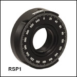
The RSP1(/M) Continuous Rotation Mount utilizes two precision bearings for smooth, backlash-free rotation. The aperture is threaded with our internal SM1 threading (1.035"-40) and accepts Ø1" optics up to 0.47" (11.9 mm) thick. Secure the optic with the included SM1RR retaining ring. The SM1 threading also provides a means to connect SM1 lens tubes and other Thorlabs components to the mount.
This mount has a knurled edge for adjusting rotation. A 360° laser-engraved scale marked at 2° increments allows for precise, repeatable positioning and fine angular adjustment. A top-located setscrew can be tightened with a 5/64" (2.0 mm) hex key or balldriver to lock the rotation of the mount.

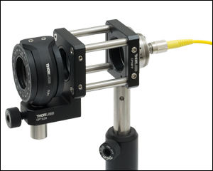
Click to Enlarge
Figure 648B Dual Rotation Mount Integrated in a 30 mm Cage System using CPTS20 Adapter
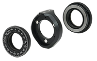
Click to Enlarge
Figure 648A The rotating optic carriages can be easily removed from the main body of the mount.
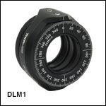
- Mount Two Ø1" Optics up to 0.25" (6.4 mm) Thick
- Each Optic Carriage Rotates Independently
- Rotating Optic Carriages are Interchangeable for Quick Swapping
- SM1-Threaded Optic Bore in Each Rotating Optic Carriage
- Two SM1RR Retaining Rings Included
- Post Mountable via 8-32 (M4) Tap
The DLM1(/M) Dual Rotation Mount includes two independently rotating carriages (item # DLM1-A) for Ø1" optics that offer 360° of continuous rotation. The optic bore of each carriage features internal SM1 (1.035"-40) threading and can hold an optic up to 0.25" (6.4 mm) thick with the included SM1RR retaining ring. The carriages magnetically attach to the main body of the mount. To remove a carriage from the mount, simply pull the carriage off the main body. Another carriage can then be snapped on in its place. Extra DLM1-A interchangeable rotating carriages are available to allow optics to be swapped out quickly and easily.
Each carriage has a knurled edge for adjusting rotation and a 360° laser-engraved scale marked at 2° increments for precise, repeatable positioning. Two top-located setscrews can be tightened with a 5/64" (2.0 mm) hex key or balldriver to lock the rotation of the optic carriages independently. When the rotation is locked, the double bore on the mount maintains a stable, three-point contact to hold the optic carriage.
The DLM1 mount is designed to put the optic axis 1.00" above the top of the post. The DLM1/M puts the optic axis 25.0 mm above the top of the post. When two optics are mounted, the separation between them is 0.30" (7.6 mm). The dual rotation mount is ideal for creating variable polarizers and attenuators by mounting linear polarizers and wave plates in close proximity without having to align the optic axes of two separate rotation mounts. We do not recommend using this mount with lens tubes, as the torque applied to the optic bore may overcome the magnetic attachment. Optics in SM1-threaded housings can be mounted to the carriage.

Video 438A This animation shows the movable scale of the Ø2" RSP2D Mount being rotated to align with the fast axis of a wave plate.
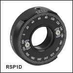
- Mount Ø1" Optics up to 0.51" (12.9 mm) Thick
- Dial Face Can Be Rotated Independently of Mounted Optics
- 5 arcmin Vernier Scale
- Compatible with SM1 Lens Tubes
- One SM1RR Retaining Ring Included
- Bottom-Located 8-32 (M4) Tapped Hole for Post Mounting
The RSP1D(/M) Ø1" Continuous Rotation Mount offers the same features as the RSP1(/M) featured above but also incorporates a rotatable dial that can be used, for example, to align a wave plate's optical axis after mounting. Like the RSP1 above, this mount utilizes two precision bearings for smooth, backlash-free rotation. The aperture is threaded with our internal SM1 threading (1.035"-40) and accepts Ø1" optics up to 0.51" (12.9 mm) thick. Secure the optic's position using the included SM1RR retaining ring. The SM1 threading also provides a means to connect SM1 lens tubes and other Thorlabs components to the mount.
This mount has a knurled edge for adjusting rotation and a 360° laser-engraved scale marked at 2° increments to allow for precise, repeatable positioning and fine angular adjustment. The front dial scale can be unlocked and rotated using a 5/64" (2.0 mm) hex key so that the scale can be aligned to the axis of an optic for calibration purposes. A top-located setscrew can be tightened with a 5/64" (2.0 mm) hex key or balldriver to lock the rotation of the mount.

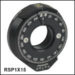
- Directly Mounts Ø1" Optics up to 0.50" (12.7 mm) Thick
- Scale can be Rotated Independently of Mounted Optic for Alignment
- Switch Between Continuous and Discrete Rotation
- RSP1X15(/M): Discrete Rotation in 15° Increments
- RSP1X225(/M): Discrete Rotation in 22.5° Increments
- 5 arcmin Vernier Scale is Ideal for Polarization Optics
- One SM1RR Retaining Ring Included
- Post Mountable via 8-32 (M4) Tap
The RSP1X15(/M) and RSP1X225(/M) rotation mounts for Ø1" optics feature both continuous 360° rotation and stepped rotation in increments of 15° for the RSP1X15(/M) or 22.5° for the RSP1X225(/M). The top of each mount has a setscrew that, when loosened with a 5/64" (2.0 mm) hex key or balldriver, allows for smooth, continuous, 360° rotation. Tightening the setscrew engages a detent mechanism that forces the mount to rotate in discrete increments. The mounted optic is retained in the central SM1-threaded (1.035"-40) bore using the included SM1RR retaining ring.
In addition, the engraved scale can be unlocked and rotated independently of the optic so that the markings can be aligned with respect to the mounted optic. For example, the zero of the engraved scale can be aligned with the fast axis of a wave plate or the polarization axis of a linear polarizer. To help with the alignment, an engraved arrow extends the zero mark all the way to the outside edge of the SM1-threaded bore used to mount the optic. Video 332A details the operation of the RSP1X15.

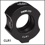
- Holds Ø1" Optics up to 0.50" (12.7 mm) Thick
- Ideal for Round Cylindrical Lenses
- Rotationally Align Optics Within a Lens Tube System
- Post Mountable via 8-32 (M4) Tapped Hole
- Features SM1 Quick Release Adapter on Back of Mount
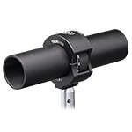
The CLR1(/M) is a rotation mount designed for use with Ø1" round cylindrical lenses and other rotationally sensitive optics within a lens tube system. As round cylindrical lenses only focus or expand light in one dimension, they are not easily aligned within a standard lens mount or lens tube. This rotation mount can be sandwiched between two lens tubes to provide rotation of the mounted optic without disturbing the attached lens tubes.
The back side of this mount utilizes an SM1 (1.035"-40) quick release adapter, which allows the mount to be quickly disconnected and reconnected to a lens tube setup. Please note that this adapter must be removed while inserting an optic in the mount, but once the optic is mounted, the adapter can be reattached. A convenient top-located setscrew can be tightened with a 0.05" (1.3 mm) hex key or balldriver to secure the rotational position of the mount.

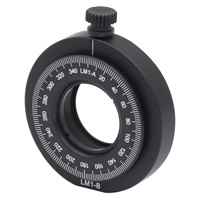
Click to Enlarge
Figure G1.1 The optic carriage is locked in place by a thumbscrew and can be easily removed from the main body of the mount.
- Mount Ø1" Optics up to 0.37" (9.4 mm) Thick
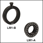
- Optic Carriage (LM1-A) and Mounting Ring (LM1-B or LM1-B/M) Sold Separately
- Rotating Optic Carriage is Interchangeable for Quick Swapping
- SM1-Threaded Optic Bore in Rotating Optic Carriage
- Post Mountable via 8-32 (M4) Tap
- Laser Engraved Graduation Marks Every 2°, Labeled Every 20°
The LM1-A optic carriage can be nested inside of the LM1-B (LM1-B/M) mounting ring and offers 360° of continuous rotation for Ø1" optics. The optic bore of the LM1-A carriage features internal SM1 (1.035"-40) threading and can hold an optic up to 0.37" (9.4 mm) thick with the included SM1RR retaining ring or an optic in an SM1-threaded housing. The carriage attaches to the main body of the mount using a thumbscrew. To remove the carriage from the mount, simply loosen the thumbscrew. Extra LM1-A interchangeable rotating carriages are available to allow optics to be swapped out quickly and easily.
Each carriage has a 360° laser-engraved scale marked at 2° increments for precise, repeatable positioning. The top-located thumbscrew can be tightened to lock the rotation of the optic carriage and, along with the double bore on the mount, maintains a stable, three-point contact to hold the optic carriage. When the

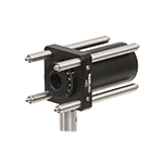
Click to Enlarge
Figure 316A CRM05 Mount in a 30 mm Cage System
- Mount Ø1/2" Optics up to 0.26" (6.5 mm) Thick
- Internal Bore is SM05 (0.535"-40) Threaded for Compatibility with SM05 Lens Tubes
- External SM1 (1.035"-40) Threads for Mounting in SM1 Lens Tubes or 30 mm Cage Cubes
- One SM05RR Retaining Ring Included
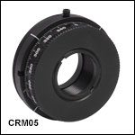
The CRM05 is a lockable, continuous-rotation mount for Ø1/2" optics. The mount features full 360° rotation of the front dial face and a setscrew for locking the rotational position into place. External SM1 threads (1.035"-40) allow the mount to be threaded directly onto any internally SM1-threaded device such as SM1 lens tubes or 30 mm cage cubes. The center aperture is SM05-threaded (0.535"-40) and accepts Ø1/2" (Ø12.7 mm) optics up to 0.26" (6.5 mm) thick. Optics are held in the mount with an included SM05RR retaining ring. Two notches along the mount's circumference accommodate the SPW801 adjustable spanner wrench to aid in securing the mount into place.
The knurled edge of the CRM05 and the 360° laser-engraved scale marked at 2° increments allow for precise, repeatable positioning and fine angular adjustment. Four equally spaced witness lines are engraved into the mount's perimeter, ensuring there is always a witness line in a convenient and easily readable position. The mount can be locked into position using the 0.035" hex setscrew on the outer edge.

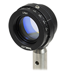
Click to Enlarge
Figure 665A A linear polarizer is mounted in the LRM1 continuous rotation mount. This rotation mount can be post mounted by attaching its external SM1 threads to the LMR1(/M) lens mount.
- Mount Ø1" Optics up to 0.34" (8.6 mm) Thick
- Internal Bore is SM1 (1.035"-40) Threaded for Compatibility with SM1 Lens Tubes
- External SM1 Threads for Mounting in SM1 Lens Tubes or 30 mm Cage Cubes
- One SM1RR Retaining Ring Included
- Not Post Mountable
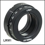
The LRM1 is a lockable, continuous-rotation mount for Ø1" optics. The mount features full 360° rotation of the front dial face and a setscrew for locking the rotational position into place. External SM1 threads (1.035"-40) allow the mount to be threaded directly onto any internally SM1-threaded device such as SM1 lens tubes or 30 mm cage cubes. Please note that the LRM1 will not fit inside our 30 mm cage systems. The center aperture is also SM1-threaded and accepts Ø1" (Ø25.4 mm) optics up to 0.34” (8.6 mm) thick. Optics are held in the mount with an included SM1RR retaining ring. We recommend using a spanner wrench for the SM1RR retaining ring to help secure the optic into place. In addition, two notches along the mount's circumference accommodate the SPW801 adjustable spanner wrench to aid in securing the mount into place.
The knurled edge of the LRM1 and the 360° laser-engraved scale marked at 2° increments allow for precise, repeatable positioning and fine angular adjustment. Four equally spaced witness lines are engraved into the mount's perimeter, ensuring there is always a witness line in a convenient and easily readable position. The mount can be locked into position using the 8-32 nylon-tipped setscrew on the outer edge. The setscrew can be adjusted using a 5/64" (2.0 mm) hex key or ball driver.

- 360° of Continuous Rotation, Lockable
- 2° Graduations on Dial, Labeled Every 20°
- 30 mm Cage System Compatible
The CRM1T(/M) is designed to mount Ø1" (Ø25.4 mm) optics up to 0.37" (9.4 mm) thick in an SM1 threaded rotation carriage. The optic is secured using the included SM1RR retaining ring (the SPW602 spanner wrench is ideal for tightening this retaining ring). For thicker optics, any of our SM1 series of lens tubes can be threaded into the carriage or the CRM1LT(/M) rotation mount, with a double bore and setscrew, can be used instead. The smooth rotation mechanism allows for precise positioning of the rotation carriage. The CRM1T(/M) is designed to be mounted in a 30 mm cage structure.

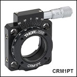
- 360° Coarse Rotation, Lockable
- 2° Graduations on Dial, Labeled Every 20°
- ±7° Precision Micrometer Adjustment
- Vernier Scale Provides 5 arcmin Resolution
- Accepts Ø1" (Ø25.4 mm) or Ø25.0 mm Optics up to 0.37" (9.4 mm) Thick
- 8-32 (M4) Tapped Mounting Hole to Mount on TR Series Posts
The CRM1PT(/M) is designed to mount Ø1" (Ø25.4 mm) optics up to 0.37" (9.4 mm) thick in an SM1 threaded rotation carriage. The optic is secured using the included SM1RR retaining ring (the SPW602 spanner wrench is ideal for tightening this retaining ring). For thicker optics, any of our SM1 series of lens tubes can be threaded into the carriage. The smooth rotation mechanism on the CRM1PT(/M) can be manually rotated to any position. When the rotation carriage is locked, the high-precision, backlash-free micrometer can then be used to fine tune the position of the rotation carriage over a range ±7°. The animation to the right illustrates how the CRM1PT(/M) is used. The Vernier scale provides a resolution of 5 arcmin between consecutive marks. As the mount is rotated across the entire Vernier scale, there is a cumulative error of up to ±12.28 arcmin. The CRM1PT(/M) is compatible with the 30 mm cage system and the 8-32 (M4) tapped mounting hole allows the rotation mount to be secured on a TR series post.
This mount is also mechanically compatible with Ø25.0 mm optics, but we only recommend this for applications in which the centration of the optics is not critical.

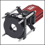
Click to Enlarge
The LCP16R1 rotation mount in a 60 mm cage system with the CS2100M-USB Quantalux® camera and the LCP4S cage plate adapter.
Click to Enlarge
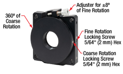
This mount offers 360° of coarse rotation via the rotation ring and ±8° of fine rotation via the threaded adjuster. The coarse and fine rotation are independent of each other and both positions can be locked using the respective 5/64" (2 mm) hex locking screws.
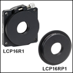
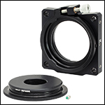
The LCP16R1 mount includes an LCP16RP1 SM1-threaded rotation ring that can be removed (left) and replaced with an LCP16RP2 SM2-threaded rotation ring (right).
- Mount Ø1" (Ø25.4 mm) Optics or SM1-Threaded Components
- Ø0.95" (Ø24.1 mm) Clear Aperture
- ±8° of Fine Rotation; 360° of Manual Coarse Rotation
- 1° Engraved Graduations, Labeled Every 2° up to ±8°
- Setscrew Locking Mechanism
- Suitable for Cantilevered Loads up to 0.5 ft-lbs (0.68 N•m) Torque
- Includes LCP16RP1 Removable Rotation Ring
- One 8-32 (M4 x 0.7) Tapped Hole for Post Mounting
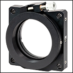
Thorlabs' LCP16R1(/M) 60 mm Cage System Rotation Mount with SM1 Threads provides ±8° of fine and 360° of coarse rotation angle adjustment for SM1-threaded components integrated with a 60 mm cage system. A nylon-tipped setscrew secures the included LCP16RP1 rotation ring; this setscrew can be loosened using a 5/64" (2 mm) hex key to allow for 360° of manual rotation (see the image to the right). Once this screw is tightened, fine rotation adjustment is achieved via a 3/16"-100 threaded adjuster. A fine adjustment scale engraved on the top of the mount has graduations every 1° with a range of ±8°.
This mount features four through holes for ER cage rods that are compatible with Thorlabs' 60 mm cage system or cameras that use this hole pattern, such as our scientific CCD cameras. The removable rotation ring on the front of the mount has 0.40" (10.1 mm) deep internal SM1 (1.035"-40) threads, allowing Ø1" (Ø25.4 mm) optics, Ø1" lens tubes, or other externally SM1-threaded components to be integrated with the rotation mount. Internally C-mount threaded components, such as Thorlabs' USB C-Mount CCD, Quantalux® sCMOS, or Kiralux™ CMOS cameras, can be attached to the rotation ring using an SM1A39 adapter; alternatively, the SM1T2 coupler can be used to connect internally SM1-threaded components, such as Zelux® CMOS cameras or a selection of our microscope port adapters. Note that the back of the SM1-threaded bore has a retaining lip, so SM1-threaded components can only be mated to the front side.
Users can switch out the included SM1-threaded LCP16RP1 rotation ring with the SM2-threaded LCP16RP2 rotation ring to integrate SM2-threaded components into the LCP16R1(/M) mount; see the image to the right. We also offer the LCP16RP1 rotation ring separately in case a replacement is needed. To switch the rotation ring in a mount, loosen the side-located setscrew using a 5/64" (2 mm) hex key and replace the rotation ring with the desired one.
We also have available an SM2-threaded 60 mm cage system rotation mount.

- Combines Kinematic Angular Adjustment with Rotation in One Mount
- Three 1/4"-80 Lockable Stainless Steel Adjusters with Removable Knobs and Brass Bushings for Smooth Adjustments
- Six #8 (M4) Counterbored Mounting Holes Allow Left-Handed or Right-Handed Orientations
- Engraved Rotation Scale with 2° Graduations Provides 360° Rotation
- SM1-Threaded (1.035"-40) Rotation Ring with Locking Screw
The KS1RS is designed to hold Ø1" (25.4 mm) optics in situations where it is necessary to control the tip/tilt position as well as the rotation of the optic. This mount is ideal for polarization optics such as linear polarizers or wave plates. In addition, our Ø1" round cylindrical lenses may also be mounted in the KS1RS when it is necessary to adjust the angle of the line produced at the focal plane. The KS1RS features an SM1-threaded bore capable of mounting Ø1" optics up to 0.47" (11.9 mm) thick using the included SM1RR retaining ring. Additionally, SM1 lens tubes may be threaded onto the mount to accommodate thicker optics.
Thorlabs' Kinematic Rotation Mounts combine the features of our Precision Kinematic Mirror Mounts and Manual Rotation Mounts, providing continuous 360° rotational adjustment and ±4° kinematic tip/tilt adjustment. These mounts are therefore ideal for holding optics with rotational
The rotation of the mount may be locked in position with a locking screw. The locking screw is activated using a 5/64" (2 mm) hex key. The kinematic adjustment is provided by three 1/4"-80 adjusters with brass bushings to provide smooth adjustment. Each adjuster may be locked with a locking screw using a 5/64" (2 mm) hex key.
Please note that while this mount is designed to hold Ø1" optics, the mount uses the same form factor as the KS2 Ø2" mirror mount in order to incorporate the rotation ring.
If higher adjustment resolution or control is desired, the 1/4"-80 adjusters used in these mounts can be switched with DAS110 or DM22 Differential Adjusters.

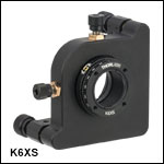
Video 280A K6XS 6-Axis Kinematic Mount Usage
- Six Adjustment Axes with Locks
- Kinematic Pitch/Yaw: ±4° at 5 mrad/rev
- X and Y Translation: ±2 mm at 254 µm/rev
- Z Translationa: ±0.13" (±3.2 mm) at 318 µm/rev
- Continuous 360° Roll Control with 1° Graduations
- Independent X, Y, and Roll Adjustment
- SM1-Threaded Bore for Ø1" (25 mm) Optics up to 0.55" (14 mm) Thick
- Six #8 (M4) Counterbores for Post Mounting
The K6XS 6-Axis Kinematic Optic Mount is designed as a general-purpose, high-precision positioner. The optic cell can be translated along 6 axes, and each axis has a locking screw for stability. The translating cell has SM1 (1.035"-40) threading for attaching Ø1" lens tubes or mounting Ø1" (25 mm) optics up to 0.55" (14 mm) thick using the included SM1RR Retaining Ring, which can be tightened using an SPW602 or SPW606 Spanner Wrench (sold separately). The rotating dial has tapped 4-40 holes for attaching the K6A1 (sold separately below).
In testing, the K6XS was shown to drift less than 15 µrad in 48 hours at typical environmental conditions, with a 2 °C temperature fluctuation. The X and Y axes cause less than ±10 µm of crosstalk when translated over their full range. If higher adjustment resolution is desired for pitch, yaw, or z-translation, the three 1/4"-80 adjusters can be replaced with DAS110 Differential Adjusters.
For more information on our 6-axis kinematic mounts, including versions for Ø1/2" and Ø2" optics, see our full web presentation.

and ±5° of fine rotation.
- 360° Coarse Rotation
- 1° Graduations on Main Dial
- Vernier Scale Provides 5 arcmin Resolution
- 2.4 arcmin per Micrometer Division
- When Locked, Micrometer-Driven ±5° of Fine Rotation
- Load Capacity for Coarse Adjustment: 25 lbs (11.25 kg)
- Load Capacity for Fine Adjustment: 3.75 lbs (1.7 kg)
- Accepts Ø1" Optics up to 0.70" Thick
The PR01(/M) Precision Rotation Platform combines easy-to-use manual rotation with high-precision, backlash-free micrometer adjustment. As shown in the animation to the right, while the platform dial is in an unlocked state, continuous smooth rotation can be measured using the 1º graduation marks. When locked via the steel thumbscrew (visible in the image to the above left), the dial is adjusted by a ±5º micrometer drive system, offering 5 arcmin resolution from the side vernier. The PR01(/M) has a load capacity of 25 pounds.
The SM1 (1.035"-40) tapped hole provides a Ø0.94" (24 mm) clear aperture at the base and 0.75" (19 mm) of usable thread. An array of 1/4"-20 (M6), #6-32 (M4), and #4-40 tapped holes offer a range of mounting options. While the 1/4"-20 (M6) tapped holes are for general purpose mounting, the #6-32 (M4) tapped holes provide compatibility with our PM1/PM2 series of clamping arms for applications including prism mounting. The #4-40 tapped holes are spaced for direct compatibility with our 30 mm Cage System rod spacing.
For optomechanical applications requiring a solid center rather than the SM1 tapped hole, the PR01A adapter plate is available.
Four 1/4" (M6) clearance slots are spaced for direct fastening to an optical table. An additional 1/4"-20 (M6) tapped hole on the edge opposite the micrometer drive allows for vertical mounting.

| Specification | Value |
|---|---|
| Linear Translation Mechanism | Bearings in V-Groove |
| Max Load | 10 lbs (4.5 kg) |
| Max Vertical Loada | 2 lbs (0.9 kg) |
| Mounting Platform Dimension | Ø4.18" (Ø106 mm) |
| Stage Height | XYR1(/M): 1.00" (25.4 mm) OCT-XYR1(/M): 1.65" (41.8 mm) |
| Stage Footprint without Actuators | 5.50" x 4.42" (139.7 mm x 112.3 mm) |
| XY Micrometers | |
| Travel | 0.025" (0.5 mm) per Revolution |
| Translation Range | 1/2" (13 mm) |
| Graduation | 0.001" (10 µm) per Division |
| Rotation | |
| Continuous Rotation Range | 360° |
| Graduation | 1° |
- 1/2" (13 mm) Linear Travel along X and Y Axes
- 360° of Continuous Rotation
- Low-Profile Stages for Imaging Applications
- Available with or without Removable Top Plate
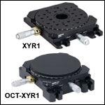
The XYR1(/M) is a low-profile XY axis translation stage with continuous rotation about the Z axis. The central SM1-threaded (1.035"-40) through hole allows the stage to be used in an imaging application that requires illumination from underneath the sample. The OCT-XYR1(/M), used with our OCT Systems, features a removable top plate that is secured through the SM1-threaded through hole. Removing the top plate provides access to the same tapped holes available with the XYR1 stage. The XYR1A Solid Sample Plate can be purchased separately to add a flat surface to an XYR1(/M) stage.
These stages contain an array of 1/4"-20 (M6) and 8-32 (M4) tapped holes for mounting samples and components. In addition, the top of the stages have eight 4-40 tapped holes around the central through hole so that it can be used with Thorlabs' 30 mm or 60 mm cage system without the use of adapters. There are also four 4-40 tapped holes on the bottom for use with 60 mm cage components.
The X and Y axis micrometers on the translation stages have a travel range of 1/2" (13 mm). An engraved angular scale along the outer edge of the stage's mounting surface allows the user to set the angular orientation of the stage, which can then be fixed using a locking setscrew. Locking the rotation axis does not prevent translation along the X and Y axes. To prevent attached components from interfering with the stage’s rotation or translation, the top surface of the rotation platform is above the frame of the XYR1(/M). The stage can also be mounted in a vertical orientation to enable XZ translation. Note that the vertical actuator should be pushing upward against gravity to support the vertical load and ensure proper translation. When mounting the stage vertically, please ensure there is a sufficient amount of clearance for the vertical actuator as well as any intended downward travel.
These stages are also compatible with Microscope Slide Spring Clips. They have 3 alignment holes for the Ø1/8" × 1/4" dowel pins (included with the SLH1). These dowel pins center the middle of a 1" × 3" microscope slide over the through hole, as well as allow the user to repeatedly and accurately position the slides on the stage. The spring clips include two 8-32 (M4) threaded shoulder screws with a 3/32" (2.5 mm) hex socket for simple attachment to the stage.
 Products Home



 Zoom
Zoom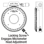 Click for Details


 SM1-Compatible Manual Rotation Mounts