 Products Home
1.6 MP CMOS Compact Scientific Cameras
- Monochrome and Color CMOS Cameras
- High Quantum Efficiency and Low <4.0 e- Read Noise
- Versions Available with External Hardware Triggers
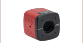
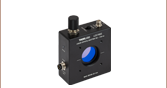
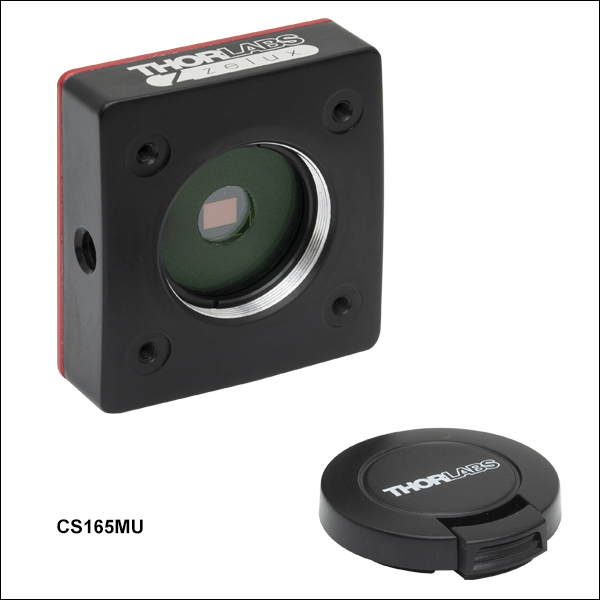
CS165MU1
Monochrome CMOS Camera with External Hardware Trigger
CS165MU
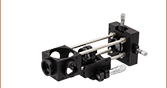
SM1A10Z
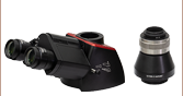
MVL4WA
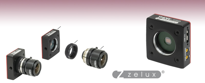
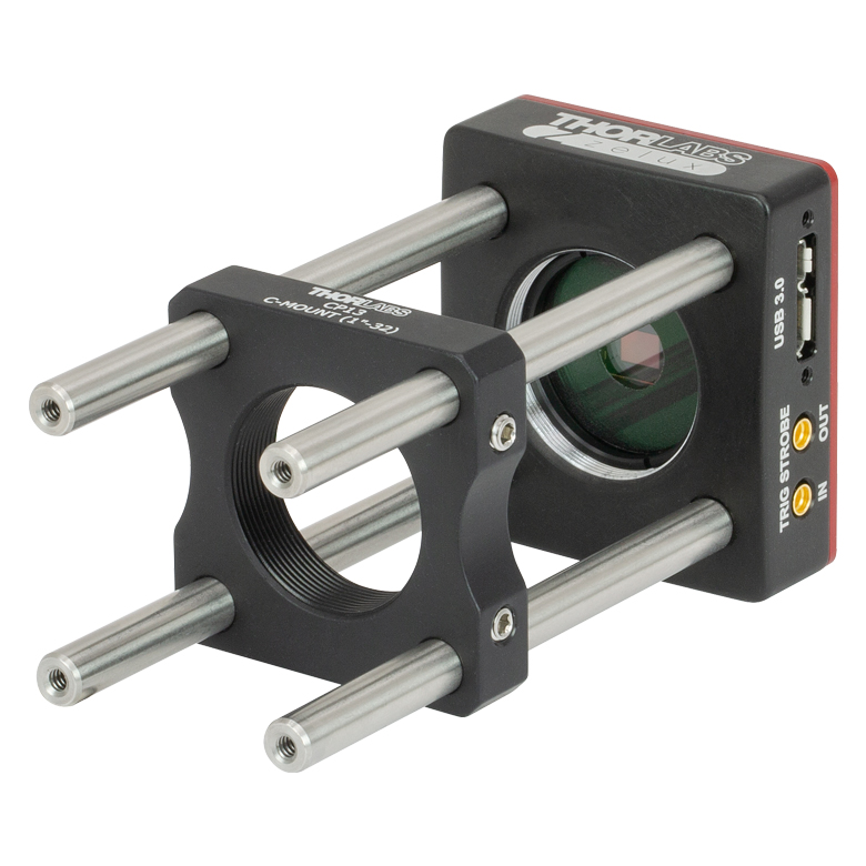
Application Idea
Use the SM1 Threads on the Camera Front with a C-Mount or CS-Mount Adapter
C-Mount and CS-Mount Adapters are Sold Below


Please Wait
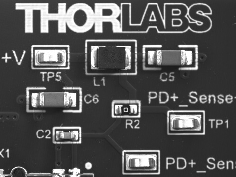
Images Taken Using Zelux® CMOS Cameras
Features
- Monochrome or Color CMOS Sensor
- 1/2.9" Format, 1440 x 1080 Pixel (1.6 MP) Sensor with 3.45 µm Square Pixels
- Global Shutter for Imaging Rapidly Changing Scenes
- USB 3.0 Interface
- Compatible with 30 mm Cage System
- Ultra-Compact Housing: 0.59" x 1.72" x 1.86"
- SM1-Threaded (1.035"-40) Aperture
- C-Mount and CS-Mount Adapters Sold Below
- Available with Either 1/4"-20 or M6 Tapped Holes for Post Mounting
Software
- ThorCam™ Software for Windows® 7, 10, and 11 Operating Systems
- SDK and Programming Interfaces Provide Support for:
- C, C++, C#, Python, and Visual Basic .NET APIs
- LabVIEW, MATLAB, and µManager Third-Party Software
Thorlabs' ultra-compact, lightweight Zelux® Cameras with CMOS Sensors are designed to provide the imaging performance of a scientific camera at the price of a typical general-purpose camera. We have available cameras with either monochrome or color CMOS sensors and offer versions with or without MMCX connectors for external triggering to synchronize image capture with other devices. These cameras have a low <4.0 e- read noise and high sensitivity while maintaining a small footprint. The global shutter captures the entire field of view simultaneously, allowing for imaging of rapidly changing scenes.
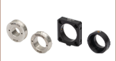
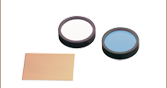
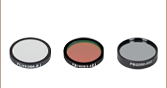
The monochrome cameras feature a clear AR-coated window, while the color cameras feature an IR blocking filter that cuts off transmission above 650 nm. The window and filter are held in place by an SM1RR Retaining Ring, which can be tightened using an SPW602 or SPW606 Spanner Wrench (sold separately); each optic can be removed and replaced with another Ø25 mm or Ø1" optic up to 1.27 mm thick. Both types of cameras feature a USB 3.0 interface and can be controlled through our ThorCam software; see the Software tab for more information. The most up-to-date firmware can be downloaded here. Every camera is shipped with an SM1EC2B snap-on lens cap to protect the sensor while cameras are not in use.
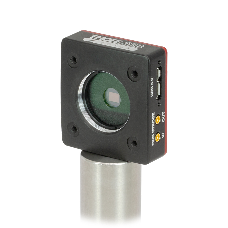
The combination of flexible mounting options and compact size makes these cameras an ideal choice for integrating into lab-built imaging systems as well as those based on commercial microscopes. Two 1/4"-20 or M6 tapped holes on adjacent sides of each Zelux camera housing provide compatibility with Ø1" pedestal or pillar posts and many standard tripod mounts. The aperture of each camera has SM1 (1.035"-40) threading for compatibility with Ø1" Lens Tubes and SM1-Threaded Adapters. CS- and C-Mount (1.000"-32) adapters are available below for compatibility with many microscopes, machine vision camera lenses, and C-mount extension tubes. See the Lens Compatibility tab for a selection of compatible machine vision camera lenses. Thorlabs also offers SM1-threaded dovetail adapters that can be used to quickly connect the camera to a 30 mm cage or SM1 lens tube system. Four 4-40 tapped holes on the front of the housing also allow the camera to be mounted directly into our 30 mm cage system.
| Scientific Camera Selection Guide |
|---|
| Zelux® CMOS (Smallest Profile) |
| Kiralux® CMOS |
| Kiralux Polarization-Sensitive CMOS |
| Quantalux® sCMOS (<1 e- Read Noise) |
 Sam Tesfai General Manager, Thorlabs Imaging Systems |
Feedback? |
| Common Specifications | |
|---|---|
| Number of Active Pixels (Horizontal x Vertical) |
1440 x 1080 |
| Imaging Area (Horizontal x Vertical) |
4.968 mm x 3.726 mm |
| Pixel Size | 3.45 µm x 3.45 µm |
| Optical Format | 1/2.9" (6.2 mm Diagonal) |
| Max Frame Rate | See Table Below |
| ADCa Resolution | 10 Bits |
| Sensor Shutter Type | Global |
| Read Noise | <4.0 e- RMS |
| Full Well Capacity | ≥11 000 e- |
| Exposure Time | 0.040 ms to 26843 ms in ~0.025 ms Increments |
| Region of Interest (ROI) | 80 x 4 Pixelsb to 1440 x 1080 Pixels, Rectangular |
| Dynamic Range | Up to 69 dB |
| Lens Mount | Internal SM1 (1.035"-40) Threading; SM1A10 CS-Mount Adapter and SM1A10Z C-Mount Adapter Sold Below |
| USB Power Consumption | 1.17 W |
| Ambient Operating Temperature | 10 °C to 40 °C (Non-Condensing) |
| Storage Temperature | 0 °C to 55 °C |
| Item # | CS165MU(/M) | CS165MU1(/M) | CS165CU(/M) | CS165CU1(/M) |
|---|---|---|---|---|
| Sensor Type | Monochrome CMOS | Color CMOS | ||
| Hardware Trigger/Strobe | No | Yesa | No | Yesa |
| Peak Quantum Efficiency | 69% at 575 nm (See Graph Below) |
65% at 535 nm (See Graph Below) |
||
| Removable Optic | AR-Coated Window, Ravg < 0.5% per Surface (400 - 700 nm) |
IR Blocking Filterb | ||
| Vertical and Horizontal Digital Binning | 1 x 1 to 16 x 16 | 1 x 1 to 16 x 16c | ||
| Mounting Features | Imperial: Two 1/4"-20 Taps for Post Mounting, 30 mm Cage Compatible Metric: Two M6 Taps for Post Mounting, 30 mm Cage Compatible Taps are on Adjacent Sides of the Housing |
|||
Click to Enlarge
Mechanical Drawing of the Zelux® Camera Housing. MMCX connectors are only included in versions with an external hardware trigger. The dimensions of metric parts are indicated in parentheses.
| Example Frame Rates at 1 ms Exposure Timea | |
|---|---|
| Region of Interest | Frame Rate |
| Full Sensor (1440 x 1080) | 34.8 fps |
| Half Sensor (720 x 540) | 67.0 fps |
| 1/10 Sensor (144 x 108) | 260.0 fps |
| Minimum ROI (80 x 4) | >800 fps |
Click to Enlarge
Click for Raw Data
This curve shows the quantum efficiency for the monochrome camera sensor.

Click to Enlarge
Click for Raw Data
These curves show the relative response for the color camera sensor's red, green, and blue pixels. This data does not take into account absorption from the installed IR blocking filter. The shaded blue region above 650 nm represents wavelengths blocked by the removable filter.
Click to Enlarge
Click for Raw Data
The curve shows the typical transmission through the IR blocking filter. The filter can be removed and replaced with another Ø25 mm or Ø1" optic up to 1.27 mm thick.
Camera Side Panel Connector Locations
Side panel of the CS165MU(/M) and CS165CU(/M) Zelux Cameras showing the
USB 3.0 connector port.
Side panel of the CS165MU1(/M) and CS165CU1(/M) Zelux Cameras showing the
USB 3.0 and two MMCX connector ports.
Click to Enlarge
C- vs. CS-Mount Flange Focal Distances
Click to Enlarge
Spacer Length
Click for Details
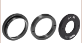
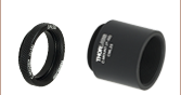
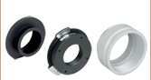
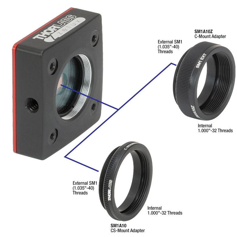
Adapters for mounting C-mount and CS-mount lens onto our Zelux cameras.
C-Mount and CS-Mount Lens Compatibility
Our Zelux® cameras are compatible with C-mount lenses via the SM1A10Z adapter, as well as with CS-mount lenses via the SM1A10 adapter. As shown in the image to the near right, these adapters can be directly connected to the SM1 (1.035"-40)-threaded aperture of a Zelux camera. Both the SM1A10Z and SM1A10 adapters are sold below.
The C- and CS-mount standards both use 1.00"-32 threads, but C-mount lenses have a flange focal distance that is 5 mm longer than CS-mount lenses, as illustrated in the diagram to the far right. Spacer length of an adapter is defined as the distance depicted by the diagram to the middle right.
Choosing a Camera Lens
Modern cameras that use CCD or CMOS sensors are specified for a camera sensor format, and similarly, lenses are designed to provide optimal imaging for a specific camera format. This format designation (e.g., 1/2", 2/3", 4/3") is a hold-over convention from when video was recorded using cathode-ray tubes and refers to the outer diameter of the video tube required for a given image size. Our Zelux cameras have a 1/2.9" (6.2 mm diagonal) optical format. In the ideal imaging system, a camera and lens would be designed for the same format, however, it is also possible to use camera/lens combinations with different formats. Doing this will have an effect, either vignetting or cropping, on the resulting image. Vignetting occurs when the lens format is smaller than the camera format, while cropping occurs when the lens format is larger than the camera format. For more details, please see our Camera Lens Tutorial.
We offer a variety of C-mount camera lenses that are compatible with the Zelux CMOS cameras via the SM1A10Z adapter. Please see the Compatible C-Mount Camera Lenses table below for specifications on a selection of our camera lenses.
| Zelux Camera Parameters | |||
|---|---|---|---|
| Number of Active Pixels (Horizontal x Vertical) |
Imaging Area (Horizontal x Vertical) |
Pixel Size | Optical Format |
| 1440 x 1080 | 4.968 mm x 3.726 mm | 3.45 µm x 3.45 µm | 1/2.9" (6.2 mm Diagonal) |
| Compatible C-Mount Camera Lensesa | |||||||||
|---|---|---|---|---|---|---|---|---|---|
| Item # | Lens Parameters | Estimated Performance at the Specified Object Working Distanceb | |||||||
| Focal Length | Angular Field of Viewc | Minimum Working Distance | Object Working Distance |
Optical Magnification |
Field of View | Smallest Resolvable Size | |||
| Diagonal | H | V | |||||||
| MVL4WA | 3.5 mm | 81.2° | 200 mm | 200 mm | 0.02 | 343 mm | 274 mm | 206 mm | 0.39 mm |
| MVL5WA | 4.5 mm | 67.4° | 200 mm | 200 mm | 0.02 | 267 mm | 213 mm | 160 mm | 0.31 mm |
| MVL6WA | 6 mm | 51.1° | 200 mm | 200 mm | 0.03 | 191 mm | 153 mm | 115 mm | 0.23 mm |
| MVL8M23 | 8 mm | 66.7° | 100 mm | 120 mm | 0.07 | 76 mm | 61 mm | 46 mm | 0.10 mm |
| MVL12WA | 12 mm | 28.1° | 300 mm | 300 mm | 0.04 | 150 mm | 120 mm | 90 mm | 0.17 mm |
| MVL12M23 | 12 mm | 26.6° | 150 mm | 150 mm | 0.08 | 71 mm | 57 mm | 43 mm | 0.09 mm |
| MVL16M23 | 16 mm | 20.4° | 200 mm | 200 mm | 0.08 | 72 mm | 58 mm | 43 mm | 0.09 mm |
| MVL25M23 | 25 mm | 13.2° | 200 mm | 200 mm | 0.13 | 46 mm | 37 mm | 28 mm | 0.06 mm |
| MVL35M23 | 35 mm | 9.8° | 200 mm | 200 mm | 0.18 | 34 mm | 27 mm | 21 mm | 0.04 mm |
| MVL50M23 | 50 mm | 12.1° | 200 mm | 200 mm | 0.25 | 23 mm | 18 mm | 14 mm | 0.03 mm |
| MVL75M23 | 75 mm | 4.6° | 1200 mm | 1200 mm | 0.06 | 96 mm | 77 mm | 58 mm | 0.11 mm |
| MVL100M23 | 100 mm | 3.4° | 2000 mm | 2000 mm | 0.05 | 119 mm | 95 mm | 71 mm | 0.14 mm |
ThorCam™
ThorCam is a powerful image acquisition software package that is designed for use with our cameras on 32- and 64-bit Windows® 7, 10, or 11 systems. This intuitive, easy-to-use graphical interface provides camera control as well as the ability to acquire and play back images. Single image capture and image sequences are supported. Please refer to the screenshots below for an overview of the software's basic functionality.
Application programming interfaces (APIs) and a software development kit (SDK) are included for the development of custom applications by OEMs and developers. The SDK provides easy integration with a wide variety of programming languages, such as C, C++, C#, Python, and Visual Basic .NET. Support for third-party software packages, such as LabVIEW and MATLAB, is available.
For customers with loan units of our Zelux® cameras, please contact imagingsales@thorlabs.com for information on software functionality and downloads.
| Recommended System Requirementsa | |
|---|---|
| Operating System | Windows® 7, 10, or 11 (64 Bit) |
| Processor (CPU)b | ≥3.0 GHz Intel Core (i5 or Higher) |
| Memory (RAM) | ≥8 GB |
| Hard Drivec | ≥500 GB (SATA) Solid State Drive (SSD) |
| Graphics Cardd | Dedicated Adapter with ≥256 MB RAM |
| Motherboard | Integrated Intel USB 3.0 Controller or One Unused PCIe x1 Slot (for Item # USB3-PCIE) |
| Connectivity | USB or Internet Connectivity for Driver Installation |
Software
Version 3.7.0
Click the button below to visit the ThorCam software page.
For the most up-to-date version of the firmware, please click here.
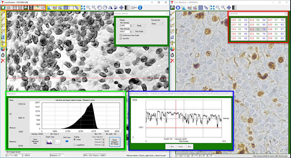
Click the Highlighted Regions to Explore ThorCam Features
Camera Control and Image Acquisition
Camera Control and Image Acquisition functions are carried out through the icons along the top of the window, highlighted in orange in the image above. Camera parameters may be set in the popup window that appears upon clicking on the Tools icon. The Snapshot button allows a single image to be acquired using the current camera settings.
The Start and Stop capture buttons begin image capture according to the camera settings, including triggered imaging.
Timed Series and Review of Image Series
The Timed Series control, shown in Figure 1, allows time-lapse images to be recorded. Simply set the total number of images and the time delay in between captures. The output will be saved in a multi-page TIFF file in order to preserve the high-precision, unaltered image data. Controls within ThorCam allow the user to play the sequence of images or step through them frame by frame.
Measurement and Annotation
As shown in the yellow highlighted regions in the image above, ThorCam has a number of built-in annotation and measurement functions to help analyze images after they have been acquired. Lines, rectangles, circles, and freehand shapes can be drawn on the image. Text can be entered to annotate marked locations. A measurement mode allows the user to determine the distance between points of interest.
The features in the red, green, and blue highlighted regions of the image above can be used to display information about both live and captured images.
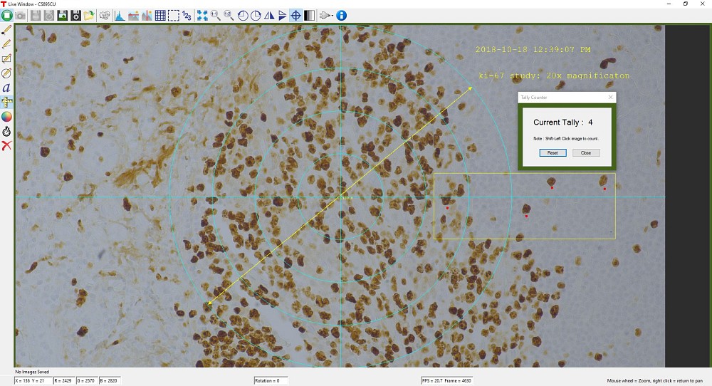
ThorCam also features a tally counter that allows the user to mark points of interest in the image and tally the number of points marked (see Figure 2). A crosshair target that is locked to the center of the image can be enabled to provide a point of reference.
Third-Party Applications and Support
ThorCam is bundled with support for third-party software packages such as LabVIEW, MATLAB, and .NET. Both 32- and 64-bit versions of LabVIEW and MATLAB are supported. A full-featured and well-documented API, included with our cameras, makes it convenient to develop fully customized applications in an efficient manner, while also providing the ability to migrate through our product line without having to rewrite an application.
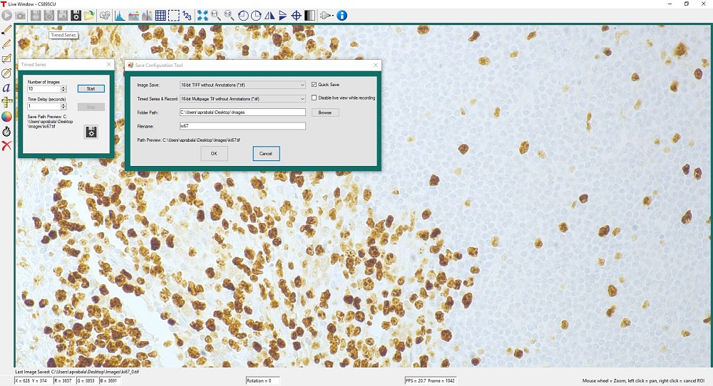
Click to Enlarge
Figure 1: A timed series of 10 images taken at 1 second intervals is saved as a multipage TIFF.
Click to Enlarge
Figure 2: A screenshot of the ThorCam software showing some of the analysis and annotation features. The Tally function was used to mark four locations in the image. A blue crosshair target is enabled and locked to the center of the image to provide a point of reference.
Performance Considerations
Please note that system performance limitations can lead to "dropped frames" when image sequences are saved to the disk. The ability of the host system to keep up with the camera's output data stream is dependent on multiple aspects of the host system. Note that the use of a USB hub may impact performance. A dedicated connection to the PC is preferred. USB 2.0 connections are not supported.
First, it is important to distinguish between the frame rate of the camera and the ability of the host computer to keep up with the task of displaying images or streaming to the disk without dropping frames. The frame rate of the camera is a function of exposure and readout (e.g. clock, ROI) parameters. Based on the acquisition parameters chosen by the user, the camera timing emulates a digital counter that will generate a certain number of frames per second. When displaying images, this data is handled by the graphics system of the computer; when saving images and movies, this data is streamed to disk. If the hard drive is not fast enough, this will result in dropped frames.
One solution to this problem is to ensure that a solid state drive (SSD) is used. This usually resolves the issue if the other specifications of the PC are sufficient. Note that the write speed of the SSD must be sufficient to handle the data throughput.
Larger format images at higher frame rates sometimes require additional speed. In these cases users can consider implementing a RAID0 configuration using multiple SSDs or setting up a RAM drive. While the latter option limits the storage space to the RAM on the PC, this is the fastest option available. ImDisk is one example of a free RAM disk software package. It is important to note that RAM drives use volatile memory. Hence it is critical to ensure that the data is moved from the RAM drive to a physical hard drive before restarting or shutting down the computer to avoid data loss.
Triggered Camera Operation
Our Zelux® scientific cameras are available with or without MMCX connectors for external triggering to synchronize image capture with other devices. For Zelux cameras with MMCX connectors, there are three externally triggered operating modes: streaming overlapped exposure, asynchronous triggered acquisition, and bulb exposure driven by an externally generated trigger pulse. The trigger modes operate independently of the readout (e.g., binning) settings as well as gain and offset. Figures 1 through 3 show the timing diagrams for these trigger modes, assuming an active low external TTL trigger.
Click to Enlarge
Figure 1: Streaming overlapped exposure mode. When the external trigger goes low, the exposure begins and continues for the software-selected exposure time, followed by the readout. This sequence then repeats at the set time interval. Subsequent external triggers are ignored until the camera operation is halted.

Click to Enlarge
Figure 2: Asynchronous triggered acquisition mode. When the external trigger signal goes low, an exposure begins for the preset time, and then the exposure is read out of the camera. During the readout time, the external trigger is ignored. Once a single readout is complete, the camera will begin the next exposure only when the external trigger signal goes low.
Click to Enlarge
Figure 3: Bulb exposure mode. The exposure begins when the external trigger signal goes low and ends when the external trigger signal goes high. Trigger signals during camera readout are ignored.
Camera Specific Timing Considerations
Due to the general operation of our Zelux CMOS cameras, as well as typical system propagation delays, the timing relationships shown above are subject to the following considerations:
- The delay from the external trigger to the start of the exposure and strobe signals is typically 12 µs to 15.5 µs for all triggered modes (standard and bulb).
- For bulb mode triggered exposures, in addition to the 12 µs to 15.5 µs delay at the start of the exposure, there is also a fixed exposure time period after the falling edge of the external trigger. This is inherent in the sensor operation.The fixed exposure time period for the CS165 models is 14.26 µs.
It is important to note that the Strobe_Out signal includes the additional fixed exposure time period and therefore is a better representation of the actual exposure time. We suggest using the Strobe_Out signal to measure exposure time and adjust the bulb mode trigger pulse accordingly
Camera Noise and Temperature
Overview
When purchasing a camera, an important consideration is whether or not the application will require a cooled sensor. Generally, most applications have high signal levels and do not require cooling. However, for certain situations, generally under low light levels where long exposures are necessary, cooling will provide a benefit. In the tutorial below, we derive the following "rule of thumb": for exposures less than 1 second, a standard camera is generally sufficient; for exposures greater than 1 second, cooling could be beneficial; for exposures greater than 5 seconds, cooling is generally recommended; and for exposures above 10 seconds, cooling is usually required. If you have questions about which domain your application will fall, you might consider estimating the signal levels and noise sources by following the steps detailed in the tutorial below, where we present sample calculations using the specifications for our 1.4 megapixel cameras. Alternatively you can contact us, and one of our scientific camera specialists will help you decide which camera is right for you.
Sources of Noise
Noise in a camera image is the aggregate spatial and temporal variation in the measured signal, assuming constant, uniform illumination. There are several components of noise:
- Dark Shot Noise (σD): Dark current is a current that flows even when no photons are incident on the camera. It is a thermal phenomenon resulting from electrons spontaneously generated within the silicon chip (valence electrons are thermally excited into the conduction band). The variation in the amount of dark electrons collected during the exposure is the dark shot noise. It is independent of the signal level but is dependent on the temperature of the sensor as shown in Table 1.
- Read Noise (σR): This is the noise generated in producing the electronic signal. This results from the sensor design but can also be impacted by the design of the camera electronics. It is independent of signal level and temperature of the sensor, and is larger for faster CCD pixel clock rates.
- Photon Shot Noise (σS): This is the statistical noise associated with the arrival of photons at the pixel. Since photon measurement obeys Poisson statistics, the photon shot noise is dependent on the signal level measured. It is independent of sensor temperature.
- Fixed Pattern Noise (σF): This is caused by spatial non-uniformities of the pixels and is independent of signal level and temperature of the sensor. Note that fixed pattern noise will be ignored in the discussion below; this is a valid assumption for the CCD cameras sold here but may need to be included for other non-scientific-grade sensors.
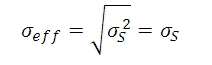
Total Effective Noise
The total effective noise per pixel is the quadrature sum of each of the noise sources listed above:
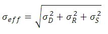
Here, σD is the dark shot noise, σR is the read noise (for sample calculations, we will use our 1.4 megapixel cameras, which use the ICX285AL sensor. Typically the read noise is less than 10 e- for scientific-grade cameras using the ICX285AL CCD; we will assume a value of 10 e- in this tutorial), and σS is the photon shot noise. If σS>>σD and σS>>σR, then σeff is approximately given by the following:
Again, fixed pattern noise is ignored, which is a good approximation for scientific-grade CCDs but may need to be considered for non-scientific-grade sensors.
| Temperature | Dark Current (ID) |
|---|---|
| -20 °C | 0.1 e-/(s•pixel) |
| 0 °C | 1 e-/(s•pixel) |
| 25 °C | 5 e-/(s•pixel) |
Click to Enlarge
Figure 1: Plot of dark shot noise and read noise as a function of exposure for three sensor temperatures for a sample camera. This plot uses logarithmic scales for both axes.The dotted vertical line at 5 s indicates the values calculated as the example in the text.
Dark Shot Noise and Sensor Temperature
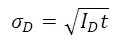
As mentioned above, the dark current is a thermal effect and can therefore be reduced by cooling the sensor. Table 1 lists typical dark current values for a sample camera with a CCD sensor. As the dark current results from spontaneously generated electrons, the dark current is measured by simply "counting" these electrons. Since counting electrons obeys Poisson statistics, the noise associated with the dark current ID is proportional to the square root of the number of dark electrons that accumulate during the exposure. For a given exposure, the dark shot noise, σD, is therefore the square root of the ID value from Table 1 (for a given sensor temperature) multiplied by the exposure time t in seconds:
Since the dark current decreases with decreasing temperature, the associated noise can be decreased by cooling the camera. For example, assuming an exposure of 5 seconds, the dark shot noise levels for the three sensor temperatures listed in the table are
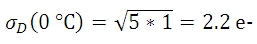
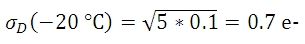
Figure 1, which is a plot of the dark shot noise as a function of exposure for the three temperatures listed in Table 1, illustrates how the dark shot noise increases with increasing exposure. Figure 1 also includes a plot of the upper limit of the read noise.
If the photon shot noise is significantly larger than the dark shot noise, then cooling provides a negligible benefit in terms of the noise, and our standard package cameras will work well.
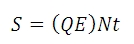
Photon Shot Noise
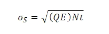
If S is the number of "signal" electrons generated when a photon flux of N photons/second is incident on each pixel of a sensor with a quantum efficiency QE and an exposure duration of t seconds, then
From S, the photon shot noise, σS, is given by:
Example Calculations (Using our 1.4 Megapixel Cameras)
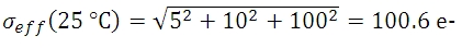
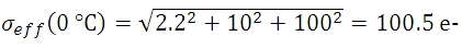
If we assume that there is a sufficiently high photon flux and quantum efficiency to allow for a signal S of 10,000 e- to accumulate in a pixel with an exposure of 5 seconds, then the estimated shot noise, σS, would be the square root of 10,000, or 100 e-. The read noise is 10 e- (independent of exposure time). For an exposure of 5 seconds and sensor temperatures of 25, 0, and -25 °C, the dark shot noise is given in equation (4). The effective noise is:

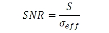
The signal-to-noise ratio (SNR) is a useful figure of merit for image quality and is estimated as:
From Equation 7, the SNR values for the three sensor temperatures are:
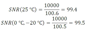
As the example shows, there is a negligible benefit to using a cooled camera compared to a non-cooled camera operating at room temperature, and the photon shot noise is the dominant noise source in this example. In this case our standard package cameras should therefore work quite well.
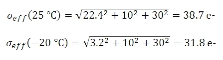
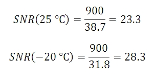
However, if the light levels were lower such that a 100 second exposure was required to achieve 900 e- per pixel, then the shot noise would be 30 e-. The estimated dark shot noise would be 22.4 e- at 25 °C, while at -20 °C the dark shot noise would be 3.2 e-. The total effective noise would be
From Equation 8, the SNR values are
| Exposure | Camera Recommendation |
|---|---|
| <1 s | Standard Non-Cooled Camera Generally Sufficient |
| 1 s to 5 s | Cooled Camera Could Be Helpful |
| 5 s to 10 s | Cooled Camera Recommended |
| >10 s | Cooled Camera Usually Required |
In this example, the dark shot noise is a more significant contributor to the total noise for the 25 °C sensor than for the -25 °C sensor. Depending on the application's noise budget, a cooled camera may be beneficial.
Figure 2 shows plots of the different noise components, including dark shot noise at three sensor temperatures, as a function of exposure time for three photon fluxes. The plots show that dark shot noise is not a significant contributor to total noise except for low signal (and consequently long exposure) situations. While the photon flux levels used for the calculations are given in the figure, it is not necessary to know the exact photon flux level for your application. Figure 2 suggests a general metric based on exposure time that can be used to determine whether a cooled camera is required if the exposure time can be estimated, and these results are summarized in Table 2. If you find that your dominant source of noise is due to the read noise, then we recommend running the camera at a lower CCD pixel clock rate of 20 MHz, since that will offer a lower read noise.

Figure 2: Noise from all sources as a function of exposure for three different photon fluxes: (a) low, (b) medium, and (c) high. In (c) the signal and photon shot noise saturate above approximately 20 seconds because the pixel becomes saturated at the corresponding incident photon levels. A quantum efficiency of 60% was used for the calculations. Note that these plots use logarithmic scales for both axes.
Other Considerations
Thermoelectric cooling should also be considered for long exposures even where the dark shot noise is not a significant contributor to total noise because cooling also helps to reduce the effects of hot pixels. Hot pixels cause a "star field" pattern that appears under long exposures. Figure 3 shows an example of this star field pattern for images taken using cameras with and without TEC cooling with an exposure of 10 seconds.
(a)

(b)
Figure 3: Images of the "star field" pattern that results from hot pixels using our (a) standard non-cooled camera and (b) our camera cooled to -20 °C. Both images were taken with an exposure of 10 seconds and with a gain of 32 dB (to make the hot pixels more visible). Please note that in order to show the pattern the images displayed here were cropped from the full-resolution 16 bit images. The full size 16 bit images may be downloaded here and viewed with software such as ImageJ, which is a free download.

Insights into Mounting Lenses to Thorlabs' Scientific Cameras
Scroll down to read about compatibility between lenses and cameras of different mount types, with a focus on Thorlabs' scientific cameras.
- Can C-mount and CS-mount cameras and lenses be used with each other?
- Do Thorlabs' scientific cameras need an adapter?
- Why can the FFD be smaller than the distance separating the camera's flange and sensor?
Click here for more insights into lab practices and equipment.
Can C-mount and CS-mount cameras and lenses be used with each other?
Click to Enlarge
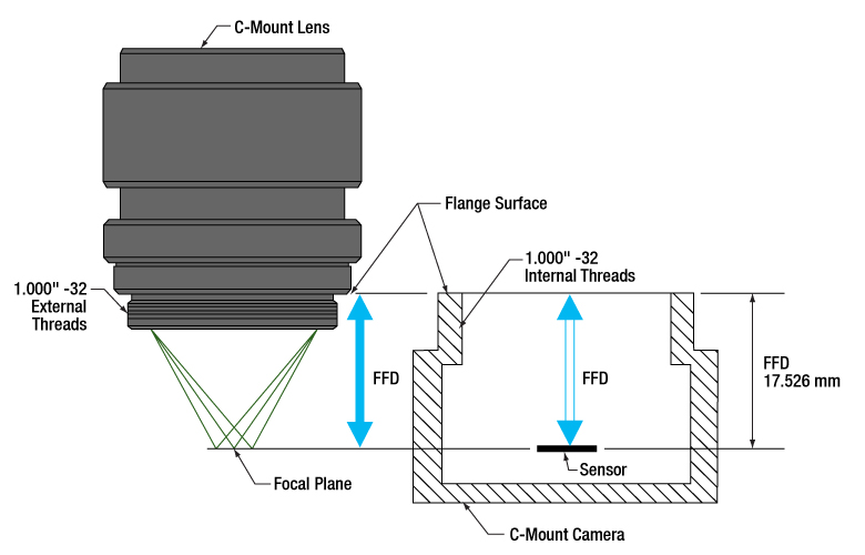
Figure 1: C-mount lenses and cameras have the same flange focal distance (FFD), 17.526 mm. This ensures light through the lens focuses on the camera's sensor. Both components have 1.000"-32 threads, sometimes referred to as "C-mount threads".
Click to Enlarge
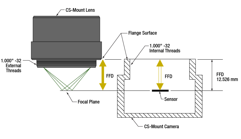
Figure 2: CS-mount lenses and cameras have the same flange focal distance (FFD), 12.526 mm. This ensures light through the lens focuses on the camera's sensor. Their 1.000"-32 threads are identical to threads on C-mount components, sometimes referred to as "C-mount threads."
The C-mount and CS-mount camera system standards both include 1.000"-32 threads, but the two mount types have different flange focal distances (FFD, also known as flange focal depth, flange focal length, register, flange back distance, and flange-to-film distance). The FFD is 17.526 mm for the C-mount and 12.526 mm for the CS-mount (Figures 1 and 2, respectively).
Since their flange focal distances are different, the C-mount and CS-mount components are not directly interchangeable. However, with an adapter, it is possible to use a C-mount lens with a CS-mount camera.
Mixing and Matching
C-mount and CS-mount components have identical threads, but lenses and cameras of different mount types should not be directly attached to one another. If this is done, the lens' focal plane will not coincide with the camera's sensor plane due to the difference in FFD, and the image will be blurry.
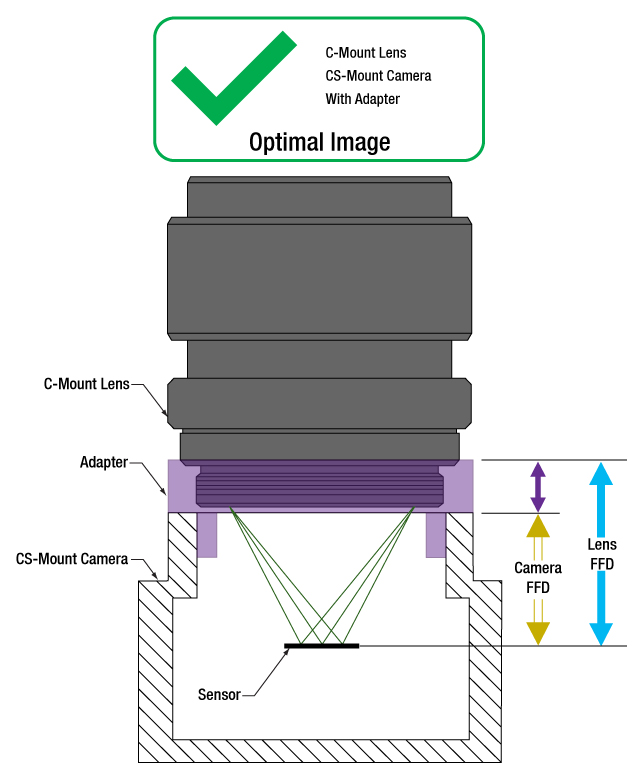
With an adapter, a C-mount lens can be used with a CS-mount camera (Figures 3 and 4). The adapter increases the separation between the lens and the camera's sensor by 5.0 mm, to ensure the lens' focal plane aligns with the camera's sensor plane.
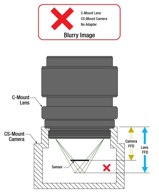
In contrast, the shorter FFD of CS-mount lenses makes them incompatible for use with C-mount cameras (Figure 5). The lens and camera housings prevent the lens from mounting close enough to the camera sensor to provide an in-focus image, and no adapter can bring the lens closer.
It is critical to check the lens and camera parameters to determine whether the components are compatible, an adapter is required, or the components cannot be made compatible.
1.000"-32 Threads
Imperial threads are properly described by their diameter and the number of threads per inch (TPI). In the case of both these mounts, the thread diameter is 1.000" and the TPI is 32. Due to the prevalence of C-mount devices, the 1.000"-32 thread is sometimes referred to as a "C-mount thread." Using this term can cause confusion, since CS-mount devices have the same threads.
Measuring Flange Focal Distance
Measurements of flange focal distance are given for both lenses and cameras. In the case of lenses, the FFD is measured from the lens' flange surface (Figures 1 and 2) to its focal plane. The flange surface follows the lens' planar back face and intersects the base of the external 1.000"-32 threads. In cameras, the FFD is measured from the camera's front face to the sensor plane. When the lens is mounted on the camera without an adapter, the flange surfaces on the camera front face and lens back face are brought into contact.

Click to Enlarge
Figure 5: A CS-mount lens is not directly compatible with a C-mount camera, since the light focuses before the camera's sensor. Adapters are not useful, since the solution would require shrinking the flange focal distance of the camera (blue arrow).
Click to Enlarge
Figure 4: An adapter with the proper thickness moves the C-mount lens away from the CS-mount camera's sensor by an optimal amount, which is indicated by the length of the purple arrow. This allows the lens to focus light on the camera's sensor, despite the difference in FFD.
Click to Enlarge
Figure 3: A C-mount lens and a CS-mount camera are not directly compatible, since their flange focal distances, indicated by the blue and yellow arrows, respectively, are different. This arrangement will result in blurry images, since the light will not focus on the camera's sensor.
Date of Last Edit: July 21, 2020
Do Thorlabs' scientific cameras need an adapter?
Click to Enlarge
Figure 6: An adapter can be used to optimally position a C-mount lens on a camera whose flange focal distance is less than 17.526 mm. This sketch is based on a Zelux camera and its SM1A10Z adapter.
Click to Enlarge
Figure 7: An adapter can be used to optimally position a CS-mount lens on a camera whose flange focal distance is less than 12.526 mm. This sketch is based on a Zelux camera and its SM1A10 adapter.
All Kiralux™ and Quantalux® scientific cameras are factory set to accept C-mount lenses. When the attached C-mount adapters are removed from the passively cooled cameras, the
The SM1 threads integrated into the camera housings are intended to facilitate the use of lens assemblies created from Thorlabs components. Adapters can also be used to convert from the camera's C-mount configurations. When designing an application-specific lens assembly or considering the use of an adapter not specifically designed for the camera, it is important to ensure that the flange focal distances (FFD) of the camera and lens match, as well as that the camera's sensor size accommodates the desired field of view (FOV).
Made for Each Other: Cameras and Their Adapters
Fixed adapters are available to configure the Zelux cameras to meet C-mount and CS-mount standards (Figures 6 and 7). These adapters, as well as the adjustable C-mount adapters attached to the passively cooled Kiralux and Quantalux cameras, were designed specifically for use with their respective cameras.
While any adapter converting from SM1 to
The position of the lens' focal plane is determined by a combination of the lens' FFD, which is measured in air, and any refractive elements between the lens and the camera's sensor. When light focused by the lens passes through a refractive element, instead of just travelling through air, the physical focal plane is shifted to longer distances by an amount that can be calculated. The adapter must add enough separation to compensate for both the camera's FFD, when it is too short, and the focal shift caused by any windows or filters inserted between the lens and sensor.
Flexiblity and Quick Fixes: Adjustable C-Mount Adapter
Passively cooled Kiralux and Quantalux cameras consist of a camera with SM1 internal threads, a window or filter covering the sensor and secured by a retaining ring, and an adjustable C-mount adapter.
A benefit of the adjustable C-mount adapter is that it can tune the spacing between the lens and camera over a 1.8 mm range, when the window / filter and retaining ring are in place. Changing the spacing can compensate for different effects that otherwise misalign the camera's sensor plane and the lens' focal plane. These effects include material expansion and contraction due to temperature changes, positioning errors from tolerance stacking, and focal shifts caused by a substitute window or filter with a different thickness or refractive index.
Adjusting the camera's adapter may be necessary to obtain sharp images of objects at infinity. When an object is at infinity, the incoming rays are parallel, and location of the focus defines the FFD of the lens. Since the actual FFDs of lenses and cameras may not match their intended FFDs, the focal plane for objects at infinity may be shifted from the sensor plane, resulting in a blurry image.
If it is impossible to get a sharp image of objects at infinity, despite tuning the lens focus, try adjusting the camera's adapter. This can compensate for shifts due to tolerance and environmental effects and bring the image into focus.
Date of Last Edit: Aug. 2, 2020
Why can the FFD be smaller than the distance separating the camera's flange and sensor?
Click to Enlarge
Figure 9: Refraction causes the ray's angle with the optical axis to be shallower in the medium than in air (θm vs. θo ), due to the differences in refractive indices (nm vs. no ). After travelling a distance d in the medium, the ray is only hm closer to the axis. Due to this, the ray intersects the axis Δf beyond the f point.;
Click to Enlarge
Figure 8: A ray travelling through air intersects the optical axis at point f. The ray is ho closer to the axis after it travels across distance d. The refractive index of the air is no .
| Example of Calculating Focal Shift | |||
|---|---|---|---|
| Known Information | |||
| C-Mount FFD | f | 17.526 mm | |
| Total Glass Thickness | d | ~1.6 mm | |
| Refractive Index of Air | no | 1 | |
| Refractive Index of Glass | nm | 1.5 | |
| Lens f-Number | f / N | f / 1.4 | |
| Parameter to Calculate |
Exact Equations | Paraxial Approximation |
|
| θo | 20° | ||
| ho | 0.57 mm | --- | |
| θm | 13° | --- | |
| hm | 0.37 mm | --- | |
| Δf | 0.57 mm | 0.53 mm | |
| f + Δf | 18.1 mm | 18.1 mm | |
| Equations for Calculating the Focal Shift (Δf ) | ||
|---|---|---|
| Angle of Ray in Air, from Lens f-Number ( f / N ) |  |
|
| Change in Distance to Axis, Travelling through Air (Figure 8) |  |
|
| Angle of Ray to Axis, in the Medium (Figure 9) |
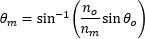 |
|
| Change in Distance to Axis, Travelling through Optic (Figure 9) |  |
|
| Focal Shift Caused by Refraction through Medium (Figure 9) | Exact Calculation |
 |
| Paraxial Approximation |
 |
|
Click to Enlarge
Figure 11: Tolerance and / or temperature effects may result in the lens and camera having different FFDs. If the FFD of the lens is shorter, images of objects at infinity will be excluded from the focal range. Since the system cannot focus on them, they will be blurry.
Click to Enlarge
Figure 10: When their flange focal distances (FFD) are the same, the camera's sensor plane and the lens' focal plane are perfectly aligned. Images of objects at infinity coincide with one limit of the system's focal range.
Flange focal distance (FFD) values for cameras and lenses assume only air fills the space between the lens and the camera's sensor plane. If windows and / or filters are inserted between the lens and camera sensor, it may be necessary to increase the distance separating the camera's flange and sensor planes to a value beyond the specified FFD. A span equal to the FFD may be too short, because refraction through windows and filters bends the light's path and shifts the focal plane farther away.
If making changes to the optics between the lens and camera sensor, the resulting focal plane shift should be calculated to determine whether the separation between lens and camera should be adjusted to maintain good alignment. Note that good alignment is necessary for, but cannot guarantee, an in-focus image, since new optics may introduce aberrations and other effects resulting in unacceptable image quality.
A Case of the Bends: Focal Shift Due to Refraction
While travelling through a solid medium, a ray's path is straight (Figure 8). Its angle
When an optic with plane-parallel sides and a higher refractive index
While travelling through the optic, the ray approaches the optical axis at a slower rate than a ray travelling the same distance in air. After exiting the optic, the ray's angle with the axis is again θo , the same as a ray that did not pass through the optic. However, the ray exits the optic farther away from the axis than if it had never passed through it. Since the ray refracted by the optic is farther away, it crosses the axis at a point shifted Δf beyond the other ray's crossing. Increasing the optic's thickness widens the separation between the two rays, which increases Δf.
To Infinity and Beyond
It is important to many applications that the camera system be capable of capturing high-quality images of objects at infinity. Rays from these objects are parallel and focused to a point closer to the lens than rays from closer objects (Figure 9). The FFDs of cameras and lenses are defined so the focal point of rays from infinitely distant objects will align with the camera's sensor plane. When a lens has an adjustable focal range, objects at infinity are in focus at one end of the range and closer objects are in focus at the other.
Different effects, including temperature changes and tolerance stacking, can result in the lens and / or camera not exactly meeting the FFD specification. When the lens' actual FFD is shorter than the camera's, the camera system can no longer obtain sharp images of objects at infinity (Figure 11). This offset can also result if an optic is removed from between the lens and camera sensor.
An approach some lenses use to compensate for this is to allow the user to vary the lens focus to points "beyond" infinity. This does not refer to a physical distance, it just allows the lens to push its focal plane farther away. Thorlabs' Kiralux™ and Quantalux® cameras include adjustable C-mount adapters to allow the spacing to be tuned as needed.
If the lens' FFD is larger than the camera's, images of objects at infinity fall within the system's focal range, but some closer objects that should be within this range will be excluded. This situation can be caused by inserting optics between the lens and camera sensor. If objects at infinity can still be imaged, this can often be acceptable.
Not Just Theory: Camera Design Example
The C-mount, hermetically sealed, and TE-cooled Quantalux camera has a fixed 18.1 mm spacing between its flange surface and sensor plane. However, the FFD (f ) for C-mount camera systems is 17.526 mm. The camera's need for greater spacing becomes apparent when the focal shift due to the window soldered into the hermetic cover and the glass covering the sensor are taken into account. The results recorded in the table beneath Figure 9 show that both exact and paraxial equations return a required total spacing of 18.1 mm.
Date of Last Edit: July 31, 2020

Thorlabs offers three families of scientific cameras: Zelux®, Kiralux®, and Quantalux®. Zelux cameras are designed for general-purpose imaging and provide high imaging performance while maintaining a small footprint. Kiralux cameras have CMOS sensors in monochrome, color, NIR-enhanced, or polarization-sensitive versions and are available in low-profile, passively cooled housings; compact, passively cooled housings; or hermetically sealed, TE-cooled housings. The polarization-sensitive Kiralux camera incorporates an integrated micropolarizer array that, when used with our ThorCam™ software package, captures images that illustrate degree of linear polarization, azimuth, and intensity at the pixel level. Our Quantalux monochrome sCMOS cameras feature high dynamic range combined with extremely low read noise for low-light applications. They are available in either a compact, passively cooled housing or a hermetically sealed, TE-cooled housing. The tables below provide a summary of our camera offerings.
| Compact Scientific Cameras | |||||||
|---|---|---|---|---|---|---|---|
| Camera Type | Zelux® CMOS | Kiralux® CMOS | Quantalux® sCMOS | ||||
| 1.6 MP | 1.3 MP | 2.3 MP | 5 MP | 8.9 MP | 12.3 MP | 2.1 MP | |
| Item # | Monochrome: CS165MUa Color: CS165CUa |
Mono.: CS135MU Color: CS135CU NIR-Enhanced Mono.: CS135MUN |
Mono.: CS235MU Color: CS235CU |
Mono., Passive Cooling: CS505MU1 CS505MU Mono., Active Cooling: CC505MU Color: CS505CU1 CS505CU Polarization: CS505MUP1 |
Mono., Passive Cooling: CS895MU Mono., Active Cooling: CC895MU Color: CS895CU |
Mono., Passive Cooling: CS126MU LP126MU(/M) Mono., Active Cooling: CC126MU Color, Passive Cooling: CS126CU LP126CU(/M) |
Monochrome, Passive Cooling: CS2100M-USB Active Cooling: CC215MU |
| Product Photos (Click to Enlarge) |
 |
 |
 |
||||
| Electronic Shutter | Global Shutter | Global Shutter | Rolling Shutterb | ||||
| Sensor Type | CMOS | CMOS | sCMOS | ||||
| Number of Pixels |
1440 x 1080 (H x V) | 1280 x 1024 (H x V) | 1920 x 1200 (H x V) | 2448 x 2048 (H x V) | 4096 x 2160 (H x V) |
4096 x 3000 (H x V) |
1920 x 1080 (H x V) |
| Pixel Size | 3.45 µm x 3.45 µm | 4.8 µm x 4.8 µm | 5.86 µm x 5.86 µm | 3.45 µm x 3.45 µm | 5.04 µm x 5.04 µm | ||
| Optical Format |
1/2.9" (6.2 mm Diag.) |
1/2" (7.76 mm Diag.) |
1/1.2" (13.4 mm Diag.) |
2/3" (11 mm Diag.) |
1" (16 mm Diag.) |
1.1" (17.5 mm Diag.) |
2/3" (11 mm Diag.) |
| Peak Quantum Efficiency (Click for Plot) |
Monochrome: 69% at 575 nm Color: Click for Plot |
Monochrome: 59% at 550 nm Color: Click for Plot NIR: 60% at 600 nm |
Monochrome: 78% at 500 nm Color: Click for Plot |
Monochrome & Polarization: 72% (525 to 580 nm) Color: Click for Plot |
Monochrome: 72% (525 to 580 nm) Color: Click for Plot |
Monochrome: 72% (525 to 580 nm) Color: Click for Plot |
Monochrome: 61% (at 600 nm) |
| Max Frame Rate (Full Sensor) |
34.8 fps | 165.5 fps | 39.7 fps | 35 fps (CS505xx1, CC505MU, CS505MUP1), 53.2 fps (CS505xx) |
20.8 fps (CC895MU), 30.15 fps (CS895xx) |
15.1 fps (CC126MU), 21.7 fps (CS126xx and LP126xx(/M)) |
50 fps |
| Read Noise | <4.0 e- RMS | <7.0 e- RMS | <7.0 e- RMS | <2.5 e- RMS | <1 e- Median RMS; <1.5 e- RMS | ||
| Digital Output |
10 Bit (Max) | 10 Bit (Max) | 12 Bit (Max) | 16 Bit (Max) | |||
| PC Interface | USB 3.0 | ||||||
| Available Fanless Cooling |
N/A | N/A | N/A | 15 °C to 20 °C Below Ambient Temperature (CCxxxMU Cameras Only) | |||
| Housing Size (Click for Details) |
0.59" x 1.72" x 1.86" (15.0 x 43.7 x 47.2 mm3) |
Passively Cooled CMOS Camera TE-Cooled CMOS Camera Passively Cooled Low-Profile CMOS Camera |
Passively Cooled sCMOS Camera TE-Cooled sCMOS Camera |
||||
| Typical Applications |
Mono. & Color: Brightfield Microscopy, General Purpose Imaging, Machine Vision, Material Sciences, Materials Inspection, Monitoring, Transmitted Light Spectroscopy, UAV, Drone, & Handheld Imaging Mono. Only: Multispectral Imaging, Semiconductor Inspection Color Only: Histopathology |
Mono., Color, & NIR: Brightfield Microscopy, Ca++ Ion Imaging, Electrophysiology/Brain Slice Imaging, Flow Cytometry, Fluorescence Microscopy, General Purpose Imaging, Immunohistochemistry (IHC), Laser Speckle Imaging, Machine Vision, Material Sciences, Materials Inspection, Vascular Imaging, Monitoring, Particle Tracking, Transmitted Light Spectroscopy, Vascular Imaging, VIS/NIR Imaging Mono. Only: Multispectral Imaging Semiconductor Inspection Color Only: Histopathology NIR Only: Ophthalmology/Retinal Imaging |
Mono. & Color: Autofluorescence, Brightfield Microscopy, Electrophysiology/Brain Slice Imaging, Fluorescence Microscopy, Immunohistochemistry (IHC), Machine Vision, Material Sciences, Materials Inspection, Monitoring, Quantitative Phase-Contrast Microscopy, Transmitted Light Microscopy Mono. Only: Multispectral Imaging Semiconductor Inspection Color Only: Histopathology |
Mono. & Color: Autofluorescence, Brightfield Microscopy, Electrophysiology/Brain Slice Imaging, Fluorescence Microscopy, Immunohistochemistry (IHC), Machine Vision, Material Sciences, Materials Inspection, Monitoring, Quantitative Phase-Contrast Microscopy, Transmitted Light Microscopy Mono. Only: Multispectral Imaging, Semiconductor Inspection Color Only: Histopathology Polarization Only: Inspection, Surface Reflection Reduction, Transparent Material Detection |
Mono. & Color: Autofluorescence, Brightfield Microscopy, Electrophysiology/Brain Slice Imaging, Fluorescence Microscopy, Immunohistochemistry (IHC), Machine Vision, Material Science, Materials Inspection, Monitoring, Quantitative Phase-Contrast Microscopy, Transmitted Light Microscopy Mono. Only: Multispectral Imaging, Ophthalmology/Retinal Imaging, Semiconductor Inspection Color Only: Histopathology LP126xx(/M), CS126xx, and CC126MU Only: Whole-Slide Microscopy |
Passive & Active Cooling: Autofluorescence, Brightfield Microscopy, Fluorescence Microscopy, Immunohistochemistry (IHC), Material Sciences, Materials Inspection, Monitoring, Quantitative Phase-Contrast Microscopy, Quantum Dots, Semiconductor Inspection, Transmitted Light Microscopy, Whole-Slide Microscopy Active Cooling Only: Electrophysiology/Brain Slice Imaging, Multispectral Imaging |
|
| Posted Comments: | |
Dan Ray
(posted 2024-09-04 15:53:37.163) Hello,
Is there a simple way to remove the protective glass window on top of the CMOS sensor?
For great coherence length it generates interferences, which are troublesome for beam imaging.
Best,
Dan cdolbashian
(posted 2024-09-17 04:05:35.0) Thank you for reaching out to us with this inquiry. The protective glass window is adhered directly to the sensor, provided to us from the chip vendor. It is quite difficult to remove, though we can still remove it ahead of time and provide it as a special. Removing that piece of glass will result in your silicon sensor being bare and unprotected. I have contacted you directly regarding the option of this special. Dovlet Seyit
(posted 2024-04-17 12:15:08.12) I just recently bought CS165MU1/M
Can this stream raw data output? I want 10 files streamed and regularly update,
Best,
Seyit. jdelia
(posted 2024-04-18 04:16:41.0) Thank you for contacting Thorlabs. I reached out to you directly to clarify your inquiry and you explained you were looking for some programming interfaces and examples for our camera software. These can be found at the ThorCam download page here: https://www.thorlabs.us/software_pages/ViewSoftwarePage.cfm?Code=ThorCam David Angeley
(posted 2024-04-16 15:20:39.023) What is the CRA (Chief Ray Angle) specification for camera CS165MU - Zelus 1.6MP monochrome? ksosnowski
(posted 2024-05-09 05:26:35.0) Hello David, thanks for reaching out to Thorlabs. Unfortunately, our sensor OEM does not specify a Chief Ray Angle for this camera. I have reached out directly to discuss your application in further detail. user
(posted 2024-04-11 08:52:42.16) The python librairies are not very user friendly. I have managed (after a long time) to obtain frames by using commands similar to the "grab_single_frame.py" example. However, the frame obtained is a grayscale image (a simple matrix) despite the fact that i'm using a color cmos camera. How can one apply white balance or color correction, for example?
Thank you for your help cdolbashian
(posted 2024-04-26 02:31:07.0) Thank you for the feedback! I have contacted you directly to make sure that you indeed have found all of our documentation as well as to assist with your particular inquiry. user
(posted 2024-03-21 11:30:36.807) The steps involved in interfacing with the camera SDKs is very convoluted, poorly documented and full of bugs (I was specifically using CS165MU/M camera in python, but the problem appears to be generic). It is not clear exactly what instructions to follow, and the steps are not clearly defined, the requirements not laid out in advance. The files are scattered in various locations. Once installed, the examples did not work. Having figured out the problem, and making one particular example work, other examples did not work (it was unable to load the libraries properly), so it was necessary to combine code preamble (library importing) from the working examples with the non-working examples. Whilst I appreciate the rationale behind the file organisation, I think this is unnecessary and simply make an installation / zip file for each supported language that contains everything with *well documented and working instructions* that ensure the examples work for that language. ksosnowski
(posted 2024-03-28 04:30:04.0) Thanks for sharing this feedback with us. As we always strive to improve our documentation and eliminate any bugs, I have reached out directly to further discuss specifics which we can address for future users' implementations. Zihao Pang
(posted 2024-03-19 21:06:58.843) Hi Thorlabs,
I want to capture the image every 100ms with the exposure time 50ms. It seems that the function "Time Series" in the software ThorCam is supposed to achieve this but the minimum timing gap is 1s.
I am reaching out for the solution? Many thanks
Zihao cdolbashian
(posted 2024-03-29 02:28:06.0) Thank you for reaching out to us with this request! You are correct, the timed series function will not be able to do this. We suggest simply using either an external hardware trigger or setting the framerate to 10hz and exposure to 50ms. This would initiate a photo every 100ms, using a 50ms exposure. p p
(posted 2024-02-18 17:58:35.69) How to control DCC3240M with Matlab R2023b? Is there any matlab adaptor? cdolbashian
(posted 2024-02-21 08:31:45.0) Thank you for reaching out to us with this inquiry! The Matlab documentation files can be found in your scientific camera documentation folder when you download the ThorCam Software. I have contacted you directly with the correct path to such files. Fabian Cadiz
(posted 2024-02-14 15:21:07.213) Hi, i am trying to run the most simple python example (grab_single_frame.py) from the github repository but i get the same error as in an older comment :
"raise TLCameraError("tl_camera_open_sdk() returned error code: {error_code}\n"
thorlabs_tsi_sdk.tl_camera.TLCameraError: tl_camera_open_sdk() returned error code: 1004"
Any help is welcomed Fabian Cadiz
(posted 2024-02-14 15:20:35.217) Hi, i am trying to run the most simple python example (grab_single_frame.py) from the github repository but i get the same error as in an older comment :
"raise TLCameraError("tl_camera_open_sdk() returned error code: {error_code}\n"
thorlabs_tsi_sdk.tl_camera.TLCameraError: tl_camera_open_sdk() returned error code: 1004"
Any help is welcomed cdolbashian
(posted 2024-02-19 11:42:00.0) Thank you for reaching out to us with this inquiry. I have contacted you directly to share the issue. It seems we are missing a line of code in our github example. We are working to update this currently. Maxime Mistretta
(posted 2024-01-18 15:28:25.12) Hello,
I would like to control our Zelux Camera (C165MU1/M) with micromanager 2.0 (I have 3 or more cameras to run simultaneously). After following precisely the installation procedure of Thorlabs Manual and the Micro-Manager_README, my camera runs with Thorcam software, but with micromanager, I cannot add TSI in "hardware configuration wizard". uManager returns "Failed to load device "TSICam" from adapter module "TSI" [Device adapter "TSI" failed to instantiate device "TSICam"].
Do you have an idea of the problem ?
Thank you in advance,
Best, ksosnowski
(posted 2024-02-05 11:30:41.0) Hello Maxime, thanks for reaching out to us. The current Micromanager "Official" release does not work with our cameras. You would need to use the latest Micromanager nightly build of 2.0 which may be found here: https://download.micro-manager.org/nightly/2.0/Windows/ . The camera dll's must then be copied to the micromanager install folder. Details can be found in the micromanager readme in "C:\Program Files\Thorlabs\Scientific Imaging\Scientific Camera Support\Scientific Camera Interfaces" as the default location. I have reached out to discuss this application further. user
(posted 2024-01-02 21:08:15.703) Dear Sir or Madam, I want to control the DCC1645C by LabView. Could you please give me any examples for a beginner? Thank you. ksosnowski
(posted 2024-01-02 11:01:47.0) Hello, thanks for reaching out to Thorlabs. LabVIEW VI's for the DCxs are included in the standard Thorcam install when you select either "DCU/DCC Series Compact CMOS and CCD Cameras" or "All Cameras" options during installation. I have reached out directly to discuss your application further. suparak dunsuk
(posted 2023-12-20 14:36:43.05) I would like to ask for help. Example LapVIEW code To order the camera to take a photo and connect to ell20k/m ksosnowski
(posted 2023-12-29 11:26:56.0) Hello Suparak, thanks for reaching out to Thorlabs. ThorCam software installation will include sample VIs and libraries by default in the C:\Program Files\Thorlabs directory of your PC. The Elliptec software does include the libraries for connection however I've reached out directly to share some example VIs for this series. user
(posted 2023-12-14 09:43:17.557) Hi, I would like to know how gain affects the camera noise: the readout noise, the dark current noise, and the hot pixels. A more basic question is: what does gain do, for example in CS165MU? Does it amplify the number of photoelectrons? I appreciate your response. ksosnowski
(posted 2024-01-22 05:15:36.0) Hello, thanks for reaching out to Thorlabs. The gain control directly corresponds to an output voltage amplifier just before the analog-to-digital converter. It does not amplify the number of photoelectrons directly, but rather the voltage produced after charge-to-voltage conversion in the sensor. The analog signal, and any noise in it, is directly proportional to the gain setting. This applies to dark current noise, photon shot noise, and any other noise originating from the sensor. There should not be an increase in hot pixels due to increasing gain, but some "mild" hot pixels that could go unseen may become more obvious. I have reached out directly to discuss your application in further detail. Riccardo Panza
(posted 2023-11-22 17:46:29.64) Hi, I want to estimate the photon flux of a fluorescence imaged with a CS165MU1/M camera, but I cannot find the conversion gain ADU/e. Can you provide this number or a way to approximate it? Thank you! cdolbashian
(posted 2023-12-11 09:23:10.0) Thank you for reaching out to us with this inquiry. I have contacted you directly to discuss a potential way to estimate the photon flux. Preston Huft
(posted 2023-09-14 11:06:15.177) Hi,
I have not been able to get the python scripts from the git repository Camera_Examples to work. For example, running grab_single_frame.py returns error 1004 when tl_camera_open_sdk() is called. Is there somewhere I can find a list of the error code meanings? I couldn't find this in the camera manuals or in the git repo. I am running Python 3.8 on Windows 10 and using the CS165CU1 camera.
Thanks, Preston cdolbashian
(posted 2023-09-25 08:40:25.0) Thank you for reaching out to us Preston. After talking to you regarding this issue, it seems like there was a missing initialization line for our simple single-frame-capture script. We have provided you with the missing line of code, as well as updated the file on the repository at Github.com/thorlabs. user
(posted 2023-06-14 08:09:18.863) Hi Thorlabs,
Can we control the camera CS165MU1 using other platforms such as Matlab and Python? If we can, Could you please give us any examples for tutorials?
Thanks,
Zihao cdolbashian
(posted 2023-06-20 02:46:44.0) Thank you for reaching out to us with this inquiry. We certainly do have such examples. Our ThorCam software also downloads various programming guides and examples for various languages. I have contacted you directly to show you where these would be found. Joris B
(posted 2023-04-04 10:49:57.763) Hi, I would like to replace the coated window by an uncoated one. What is the recommended product? (600-900nm) cdolbashian
(posted 2023-04-13 10:54:58.0) Thank you for reaching out to us with this inquiry! There are many different types of windows which could be used here, but it seems like the better advice would be to let you know where to find such guidelines determining the window dimensions. Ch 7 in the camera manual specifies how to remove the window as well as the window parameters. cdolbashian
(posted 2023-04-13 10:54:58.0) Thank you for reaching out to us with this inquiry! There are many different types of windows which could be used here, but it seems like the better advice would be to let you know where to find such guidelines determining the window dimensions. Ch 7 in the camera manual specifies how to remove the window as well as the window parameters. Peter Meinhold
(posted 2023-02-28 11:08:01.133) Would it be possible to add some beam profiling tools to Thorcam, or conversely to make Beam support scientific cameras like CS165CU? It's very common to have a camera based setup, especially a microscopy setup, with a desire for some in situ quantification, at least of basic gaussian beams. jdelia
(posted 2023-03-16 12:16:51.0) Thank you for contacting Thorlabs. While this does seem like an advantageous feature, unfortunately this is not something we have implemented or have immediate plans for implementing. However, we can certainly look into this possibility in the future. user
(posted 2023-01-25 10:54:30.7) Hi, I'm currently using a DCC1545M-GL camera + LabView 2021 (new user) and I succesfully conect to the camera and start live but couldn't find a way to get an image and store the image files. I checked the examples provided and couldn't find anything useful. Thanks. GBoedecker
(posted 2023-01-30 11:06:03.0) Thank you for your feedback! In your folder C:\Program Files\Thorlabs\Scientific Imaging\Documentation\DCx Camera Documents, there is the manual DCx_DotNET_ProgInterface.pdf. You can use the "save" class from section 3.1.1.14.6. Xavier Audier
(posted 2023-01-04 15:19:10.48) Hi,
I'm having difficulties using the Camera both using the Thorcam Software and the SDK.
I need to disable/enable the device in Windows Device Manager or reinstall drivers everytime I want to use the camera.
I've tried many things but can't seem to figure out how to get it working reliably.
Any help would be appreciated.
Best,
Xavier Audier jdelia
(posted 2023-01-17 01:57:59.0) Thank you for contacting Thorlabs. We apologize for the issue you are experiencing with our camera. I have reached out to you directly to troubleshoot your issue. xuan Lin
(posted 2022-11-22 22:30:54.64) Hi THORLABS,I want to ask about the gamma value of CS165CU.Thank you! cdolbashian
(posted 2022-11-22 03:51:50.0) Thank you for reaching out to us with this inquiry. As our cameras do not allow for this non-linear style of intensity adjustment, we would have to say that the gamma value is 1. I have reached out to you directly to discuss this further. Hang Su
(posted 2022-10-24 14:18:08.32) Hi,
I want to know if there any difference between the thorcam software and thorlabs Python SDK.
I found the received images by thorcam and SDK are very different, under the same exposure time and resolution settings. Is there any post pocessing in the thorcam software? If so, how can I republicate it in the python SDK environment?
Hope further connection for more details!
Thanks,
Hang Su cdolbashian
(posted 2022-11-16 12:13:43.0) Thank you for reaching out to us with this inquiry. This discrepancy an unfortunate difference which comes from the way data is read/saved/binned from Thorcam vs Python. Depending on what you mean by "post processing", I think the answer will likely depend on your image acquisition settings within the software. I have reached out to you directly to discuss your application. Philipp Preiss
(posted 2022-08-11 15:24:18.583) Hi there,
I'm currently capturing some fluorescence images of atomic clouds on the CS165MU/M camera and would like to calibrate absolute photon flux. I cannot find any conversion gain in ADU/e on the spec sheet. Without this number, an absolute calibration can only be performed with a somewhat tedious calibration measurement. Can you provide this additional specification for the camera.
Thank you! cdolbashian
(posted 2022-08-18 02:51:15.0) Thank you for reaching out to us with this inquiry. Calculating the exact number of photons incident on this sensor is not something we expect to do with this camera. That being said, it is possible to approximate this value. I have contacted you directly to discuss this. Sergei Poltavtsev
(posted 2022-05-21 10:10:46.453) Hallo
Apparently there is a bug in offered LabView driver. Repeatedly observed the following behavior of the supplied LabView example (as well as a custom software written with this driver): Launching of a program results in LabView crash after several (~10times) successful starts. It is tested on LabView2020+2021, on various PCs. If software addresses two such cameras, the number of successful launches shortens twice (~5-6). Zihao Pang
(posted 2022-05-16 21:21:34.18) Hi Thorlabs,
We've recently purchased your camera CS165MU1 and are wondering if it can automatically do the capturing with a fixed delay? For example, we want to take a picture every 100 ms until I had 100 pictures.
Many thanks,
Zihao jdelia
(posted 2022-05-19 10:26:13.0) Thank you for contacting Thorlabs. The CS165MU1 allows for control of the framerate within the ThorCam software. If the exposure is low enough, then you can set the framerate to 10Hz and a "frames per trigger" value of 100. This will provide 100 frames in a single click at 10Hz. user
(posted 2022-01-19 17:45:55.69) The camera gives the below error in continuous running mode after about 100 frames or immediately if illumination changes:
TLCamera2:tl_camera_close_camera:Error:tl_camera_handle=1350894998448, command='stop', command_size_bytes_including_any_null_terminator = 5, data_size_bytes = 0', response_size_bytes_up_to_1024 = 1024; Error setting data. Error: Communication failure.
ThorCam ver: 3.6.1.4, Cam firmware ver: 0.9.6
I was trying to use the camera with micro-manager but also get an error of ' failed in instantiate the device'.
Any help on getting the camera working properly would be greatly appreciated. Thank you. Oanh Ho
(posted 2022-01-19 07:26:19.697) Please let us know the price and the lead time for this camera DCC1545M (USB 20 CMOS Camera, 1280x1024, Monochrome Sensor) YLohia
(posted 2022-01-19 08:32:49.0) Thank you for contacting Thorlabs. The DCC1545M has been obsoleted and is no longer sold. My apologies for any issues caused by this. We suggest looking into its replacement, the CS165MU, instead which has a unit price of $448.05/pc and is currently in stock. Madhav Gupta
(posted 2021-11-15 05:45:00.37) Hi. I am using the CS165MU1/M camera for my application. I wanted to ask if this device is compatible with Linux? I wanted to try and use this camera with a Raspberry Pi, so wanted to know if it is compatible with Linux. Please let me know as soon as possible.
Thanks!
Best Regards,
Madhav Gupta jgreschler
(posted 2021-11-15 04:22:53.0) Thank you for reaching out to Thorlabs. The ThorCam software is exclusive to Windows, however the SDK is Linux compatible and supports all CS cameras except the CS135. You can find the download link for the Linux SDK here https://www.thorlabs.us/software_pages/ViewSoftwarePage.cfm?Code=ThorCam Keisuke Kaneshima
(posted 2021-10-11 11:38:11.85) Hello. I’m trying to use CS165MU/M with LabVIEW. I got several error messages when I ran “TLCamera Main.vi” in Windows SDK and Doc. for Scientific Cameras.
1. The class and method of the invoke node in “Open TLCameraSDK.vi” were not set properly, and the program could not load the camera. After I manually set them (Assembly: Thorlabs.TSI.TLCamera(2.0.0.0), Objects: TLCameraSDK), the program became to be able to load the camera.
2. Then I got the following message:
“Error 1172 occurred at Property Node (Arg :1) Error accessing property Thorlabs.TSI.TLCameraInterfaces.ITLCamera.TriggerPolarity, (System.Reflection.TargetInvocationException: Inner Exception: System.InvalidOperationException: TLCamera2: tl_camera_set_trigger_polarity: Error: tl_camera_handle=1920755625488, command='hwtrig', command_size_bytes_including_any_null_terminator = 7, data_size_bytes = 0', response_size_bytes_up_to_1024 = 1024: Invalid command' Error: Firmware-reported error.)
Possible reason(s):
LabVIEW: (Hex 0x494) A .NET exception occurred in an external assembly. For information about correcting this error, copy the following exception (in bold), and search the Microsoft Developer Network (MSDN) Web site or the Web for a possible explanation.
System.InvalidOperationException in Set Trigger Settings.vi->TLCamera Main.vi”
How can I fix this?
Thank you. azandani
(posted 2021-10-18 04:24:09.0) Hello Keisuke, thank you for contacting Thorlabs. We will reach out to you directly to troubleshoot. R EHU
(posted 2021-04-13 05:56:44.72) I am experiencing problems working with ThorCam software (to control a Thorlabs CMOS camera) simultaneously with Kinesis or APT software to control Thorlabs stepper motors. The two softwares seem to work correctly when they run alone, but when doing it simultaneously the camera never works. Is there an incompatibility problem? YLohia
(posted 2021-04-14 10:10:36.0) Thank you for contacting Thorlabs. We're sorry to hear about the issues you're experiencing. Could you please provide the following information?
-Computer make, model, and processor
-Windows Revision and Bit version
-Thorcam, Kinesis, and APT versions
-Part numbers of the stepper motor and controller
-Is the camera and motion control hardware being used on the same Bus? For example, adjacent ports on a PC will often be on a shared Bus.
-Are you using a USB hub?
-Are you using the Zelux with the Thorlabs cable that is included with the camera?
If you have any other information about your system that you feel may be relevant, we would be interested in getting this as well. Information such as other connected devices, concurrently running software, or present virtual machines could also be useful. I have reached out to you directly to troubleshoot this further. Perry Ellis
(posted 2021-03-10 11:46:39.023) Hi,
I'm controlling the CS165MU1 via micromanager 2.0 I notice that I have no option to tune the gain from within micromanager. The micromanager device adapter shows functions and settings to call the gain. In addition, the ThorCam 3.5.1 software can control the camera gain. I was told that y'all maintain the device adapter codes - is there an easy way to get access to the gain within uManager? Thanks. YLohia
(posted 2021-03-15 11:19:33.0) Hello, thank you for contacting Thorlabs. Unfortunately, gain has not been setup internally for our device adapter, but we have added that as an item to our work queue. Until then, there is not a way to control gain from within Micromanager. ALİ GOKMEN
(posted 2021-01-27 23:08:22.52) I have Zelux camera CS165MU/M. I could not get any image on Live Window of ThorCam software with start/stop and snapshot buttons. I am not familiar with scientific cameras. May I ask your guidance to capture an image with Zelux camera.
Info about camera and windows:
CS165MU/M , S/N: 09443.
Camera is interfaced to PC through USB 2.0 port.
Windows 10: 6 GB RAM
Processor: Intel core i5 CPU, 3.1 GHz
64 bit operating system. YLohia
(posted 2021-02-01 10:04:52.0) Hello Ali, thank you for contacting Thorlabs.
1. What version of ThorCam are you using?
2. What's the firmware version on your CS165MU/M?
3. Could you please send some screenshots of your Thorcam window showing the issue?
4. Is the camera connected directly to your computer or are you connecting it to a USB hub?
5. Have you tried using this camera on a different computer with a Thorcam installation?
I have reached out to you directly to troubleshoot further. YLohia
(posted 2021-02-01 10:04:52.0) Hello Ali, thank you for contacting Thorlabs.
1. What version of ThorCam are you using?
2. What's the firmware version on your CS165MU/M?
3. Could you please send some screenshots of your Thorcam window showing the issue?
4. Is the camera connected directly to your computer or are you connecting it to a USB hub?
5. Have you tried using this camera on a different computer with a Thorcam installation?
I have reached out to you directly to troubleshoot further. Yuhao Yuan
(posted 2021-01-26 11:12:10.45) When I connected the CS165CU1 to the computer, I could start capture for a few seconds. Then it died with a window saying 'An error communicating with the camera or acquiring data occurred'. I could reconnected the camera by re-plugging the cable but was not able to capture anymore unless I restarted my computer.
Please advise.
Thank you YLohia
(posted 2021-01-26 03:09:34.0) Hello, thank you for contacting Thorlabs. We're sorry to hear about the issues you're experiencing with the CS165CU1. Would you be able to tell us your Windows machine specs, ThorCam software version, and CS165CU1 firmware version number? We have an updater on the download page that fixed some bugs with that camera. Please ensure that you're using the latest version of the ThorCam software. Are you using this on a USB hub? We have seen this sort of issue happen previously when using 3rd party USB ports/hubs -- please be sure to use USB3-PCIE from our website in this case. I have reached out to you directly to troubleshoot this further. GT KIM
(posted 2020-09-18 04:29:51.09) HI,
I wonder relation between exposure time and frame speed in detail of this camera. For instance, I want to get image during 4 sec with 50ms exposure time when one external trigger occurs. So I change Frames per Trigger setting to 80 frames. Then I expect total 80 frames in 4 seconds of imaging time with 50ms exposure time but actual imaging time is more than 4 seconds. llamb
(posted 2020-09-22 01:42:15.0) Thank you for contacting Thorlabs. It sounds like your case is when frames/trigger is not set to continuous mode, so the exposure time and readout time are sequential (non-overlapped). In continuous mode, all but the first exposure are overlapped with readout. If elapsed time is most important, then I would recommend setting the number of frames per trigger to "continuous" and stopping the acquisition after the desired elapsed time. Pawel Czuma
(posted 2020-04-10 06:32:14.99) Dear Sir/Madam,
On RAW data spec of CS165MU1/M I see big quantum efficiency 50,396% at 235nm (I suppose after removal of AR-Coated Window). Could You send me UV QE spec of this camera in range between 200 to 300nm. I am interested especially in range 270-249nm.
Do You have any of Your camera working in such spectral range. Do You have imaging objective on working in such spectral range.
Thank You
Best Regards,
dr Pawel Czuma, Eng
Task Manager PolFEL YLohia
(posted 2020-04-10 02:32:47.0) Hello Pawel, thank you for contacting Thorlabs. We recommend our UV-enhanced 340UV-USB camera for that wavelength range. Our line of UV objectives can be found here : https://www.thorlabs.com/newgrouppage9.cfm?objectgroup_id=3271. I have reached out to you to discuss your application in more detail. |
Camera Selection Tool
Reset Parametersof 31 Products Shown
Select Parameters
Select Applications
of 31 Products Shown
| Item Number | Sensor Type | Optical Format | Electronic Shutter | Pixel Size | Max Frame Rate | Read Noise | Digital Output | Cooling | Housing Dimensions |
|---|

 Zoom
Zoom| Key Specificationsa | ||||
|---|---|---|---|---|
| Item # | CS165MU(/M) | CS165MU1(/M) | CS165CU(/M) | CS165CU1(/M) |
| Sensor Type | Monochrome CMOS | Color CMOS | ||
| Hardware Trigger/Strobe | No | Yesb | No | Yesb |
| Peak Quantum Efficiency (Click for Graph) |
69% at 575 nm | 65% at 535 nm | ||
| Removable Optic | AR-Coated Window, Ravg < 0.5% per Surface (400 - 700 nm) |
IR Blocking Filter | ||
| Mounting Features | Imperial: Two 1/4"-20 Taps for Post Mounting, 30 mm Cage Compatible Metric: Two M6 Taps for Post Mounting, 30 mm Cage Compatible Taps are on Adjacent Sides of the Housing |
|||
Zelux Mounting Features |
|||
 Click to Enlarge An MVL4WA C-Mount Machine Vision Lens is installed on a Zelux camera using an SM1A10Z adapter. |
 Click to Enlarge An SM1 Lens Tube is installed directly on the Zelux camera's SM1-threaded aperture. |
 Click to Enlarge Four 4-40 tapped holes allow 30 mm Cage System components to be attached to the camera. Pictured is our CP13 Cage Plate with C-Mount Threading. |
 Click to Enlarge A CS165MU1 Zelux camera is mounted on a Ø1" pedestal post using the 1/4"-20 tapped hole on the bottom of the housing. |

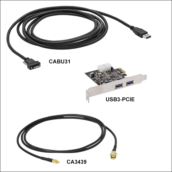 Zoom
ZoomEach Zelux® camera is shipped with a USB 3.0 Micro B to A cable (3.0 m length) and a SM1EC2B snap-on lens cap. The CS165MU1(/M) and CS165CU1(/M) Zelux cameras, which have external connections for triggering, are also shipped with two CA3339 MMCX-to-BNC cables. Additional accessories are available below.
USB 3.0 Camera Accessories (CABU31, CABU32, and USB3-PCIE)
We offer the CABU31 USB 3.0 A to straight Micro B cable for connecting our cameras to a PC (please note that one straight cable is included with each camera). The cable measures 118" long and features screws on either side of the Micro B connector that mate with tapped holes on the camera for securing the USB cable to the camera housing. We also offer the CABU32 cable with a right-angle Micro-B connector; note that this connector will block the hardware trigger connectors on cameras with this feature. When operating USB 3.0 cameras it is strongly recommended that the USB 3.0 cable provided with the camera or the CABU31 be used, with the retention screws securely fastened. Due to the high data rates involved, users may experience problems when using generic USB 3.0 cables.
All Zelux cameras may be connected directly to the USB 3.0 port on a laptop or desktop computer. Host-side USB 3.0 ports are often blue in color, although they may also be black in color, and are typically marked "SS" for SuperSpeed. A USB 3.0 PCIe card is sold separately for computers without an integrated Intel USB 3.0 controller. Note that the use of a USB hub may impact performance. A dedicated connection to the PC is preferred.
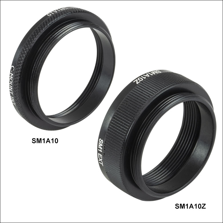
Trigger and Strobe Cables (CA3339, CA3272, and CA3439)
The CA3339 and CA3272 MMCX-to-BNC cables are 1 m and 1.8 m long, respectively. The CA3439 MMCX-to-SMA cable is 1 m long. All three are RG-174 coaxial cables with male to male connectors. They feature a DC to 6 GHz frequency range, 50 Ω impedance, and 170 V max voltage. Full details are provided at the full web presentation.
| Adapter Compatibility with Zelux Cameras | ||
|---|---|---|
| Adapter Item # | C-Mount Lenses | CS-Mount Lenses |
| SM1A10 | - |  |
| SM1A10Z | |
- |
Adapters for C- and CS-Mount Lenses (SM1A10 and SM1A10Z)
We also offer adapters for mounting C- and CS-Mount lenses to Zelux cameras. Our SM1A10 and SM1A10Z adapters have internal C-Mount (1.00"-32) threading and external SM1 (1.035"-40) threading for mounting to the SM1-threaded aperture of each Zelux camera. CS- and C-Mount standards both use 1.00"-32 threads, but C-Mount lenses have a flange focal distance (FFD) that is 5 mm longer than the FFD of CS-Mount lenses. When used with a Zelux camera, our SM1A10 adapter provides the correct FFD for CS-Mount lenses, while our SM1A10Z adapter provides the correct FFD for C-Mount lenses.