 Products Home
Precision Optical Slits
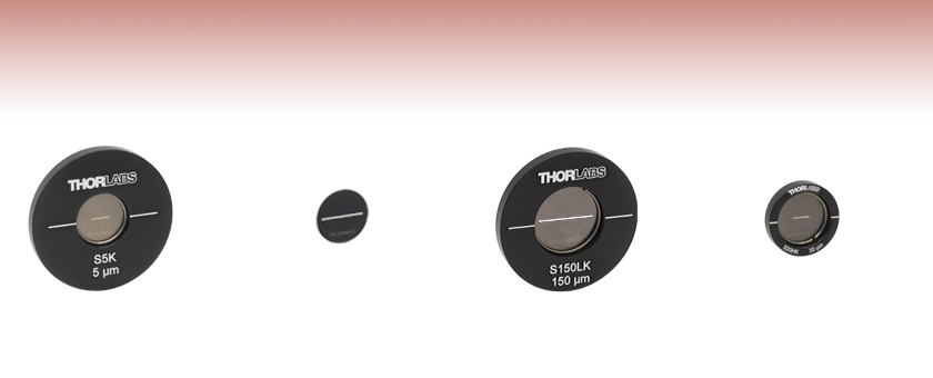
- Slit Widths from 5 to 500 µm
- 3 mm or 10 mm Slit Length
- Stainless Steel Foils Blackened on Both Sides for Increased Absorbance
- Available as Unmounted Foils or Mounted in Aluminum Housings
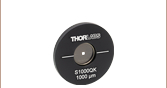
S200ULK
200 µm Slit Width,
10 mm Slit Length,
Ø1/2" Unmounted Foil
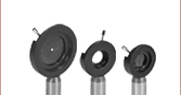
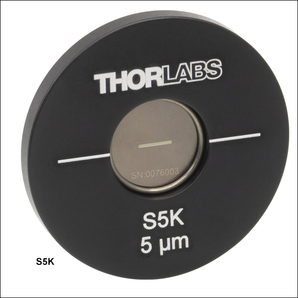
S5K
5 µm Slit Width,
3 mm Slit Length,
Ø1" Housing
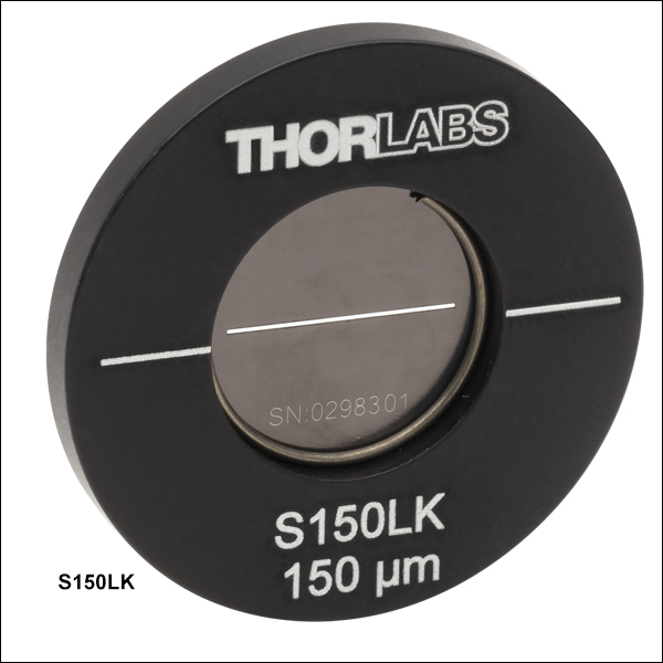
S150LK
150 µm Slit Width,
10 mm Slit Length,
Ø1" Housing
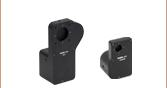
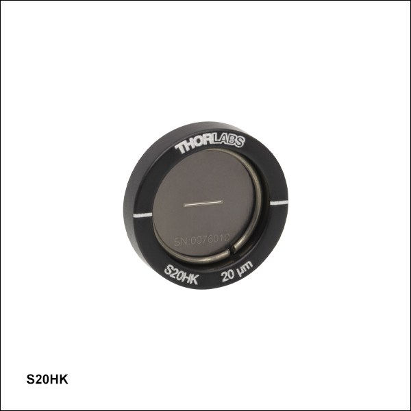
S20HK
20 µm Slit Width,
3 mm Slit Length,
Ø1/2" Housing


Please Wait
| Apertures Selection Guide |
|---|
| Single Precision Pinholes |
| Circular in Stainless Steel Foils |
| Circular in Stainless Steel Foils, Vacuum Compatible |
| Circular in Gold-Plated Copper Foils |
| Circular in Tungsten Foils |
| Circular in Molybdenum Foils |
| Square in Stainless Steel Foils |
| Pinhole Kits |
| Pinhole Wheels |
| Manual |
| Motorized |
| Pinhole Spatial Filter |
| Single Slits |
| Double Slits |
| Annular Apertures |
| Half-Aperture Foils for Knife-Edge Scans |
| Alignment Tools |
Features
- Precision Slits in Stainless Steel Foils Available Unmounted or Mounted in Aluminum Housings
- 3 mm Long Slits with Widths from 5 to 500 µm
- 10 mm Long Slits with Widths from 20 to 500 µm
- Contact Tech Support to Discuss Custom Options
Thorlabs' Optical Slits in blackened stainless steel foils have 3 mm or 10 mm slit lengths. 3 mm long slits are available from stock with 5 to 500 µm widths and mounted in Ø1/2" or Ø1" aluminum housings. 10 mm long slits are available from stock with 20 to 500 µm widths and either in unmounted Ø1/2" foils or mounted in Ø1" aluminum housings. To avoid creating a diffraction pattern in multiple directions, the slit length chosen should be longer than the size of the incident beam.
If you do not see what you need in our stocked offerings below, it is possible to special order slits that are fabricated from different substrate materials, have different slit sizes, incorporate multiple slits in one foil, or provide different slit configurations. Low-power applications may benefit more from the absorbance of blackened stainless steel foils. High-power applications may need the high damage threshold and reflectance of gold-plated copper foils, the high melting point and lower reflectance of our tungsten foils, or the high melting point of our molybdenum foils paired with the low reflectance (4% @ 800 nm) of their black-coated front side. Please see the Foil Comparison and Graph tabs for more information. Customized housings are also available. Please contact Tech Support to discuss your specific needs.
Thorlabs also offers square precision pinholes in sizes from 100 µm to 1 mm for applications with a small field of view, and double slits with widths of 40, 50, or 100 μm and spacings of 3 or 6 times the slit width for interference and diffraction experiments.
| Optical Slit Quick Links | |||
|---|---|---|---|
| 3 mm Slit Lengths, 5 to 500 µm Slit Widths | 10 mm Slit Lengths, 20 to 500 µm Slit Widths | ||
| Ø1/2" Housings | Ø1" Housings | Ø1/2" Unmounted Foils | Ø1" Housings |
| Precision Pinhole and Optical Slit Selection Guide | |||||
|---|---|---|---|---|---|
| Material | Product | ||||
| Blackened Stainless Steel | Circular Precision Pinholes | ||||
| Square Precision Pinholes | |||||
| Optical Slits | |||||
| Stainless Steel with PVD Black Coating |
Circular Precision Pinholes | ||||
| Gold-Plated Copper Foil (Rear) and PVD Black Coating (Front) |
Circular Precision Pinholes | ||||
| Tungsten Foil | Circular Precision Pinholes | ||||
| Molybdenum Foil (Rear) and Absorptive Polymer Coating (Front) |
Circular Precision Pinholes | ||||
Precision Pinholes and Slits
Thorlabs offers precision pinholes with blackened stainless steel, gold-plated copper, tungsten, or molybdenum foils. Our pinholes with stainless steel foils are blackened on both sides for increased absorbance and are available from stock in circles from Ø1 µm to Ø9 mm and squares from 100 µm x 100 µm to 1 mm x 1 mm. Our stainless steel pinholes with a black PVD coating are vacuum compatible and available in 5 μm to 2 mm diameters. Our pinholes with gold-plated copper foils, plated with gold on one side and black PVD coated on the reverse, are available with pinhole diameters from 5 µm to 2 mm. Our pinholes with tungsten foils are uncoated and available with pinhole diameters from 5 µm to 2 mm. Lastly, our pinholes with molybdenum foils have an absorptive polymer coating on the front sides and are available with pinhole diameters from 5 µm to 2 mm. We also offer slits in blackened stainless steel foils from stock with slit widths from 5 to 200 µm.
If you do not see what you need among our stock pinhole and slit offerings, it is also possible to special order pinholes and slits that are made with different foil materials, have different hole sizes and shapes, incorporatoles in one foil, or provide different hole configurations. Please contact Tech Support to discuss your specific needs. For more information on the properties of the bulk materials from which the pinholes are fabricated, see the table below.
Material Properties
Depending on the application, it can be important to consider the material properties of the pinhole or slit. The material used to construct the aperture can have varying levels of melting point, density, and thermal conductivity, as detailed in the table below.
| Material Properties | ||||
|---|---|---|---|---|
| Material | 300 Series Stainless Steela | Copperb | Tungsten | Molybdenumc |
| Melting Point | 1390 - 1450 °C | 1085 °C | 3422 °C | 2623 °C |
| Density | 8.03 g/cm3 | 8.96 g/cm3 | 19.25 g/cm3 | 10.28 g/cm3 |
| Brinell Hardness | 170 MPa | 878 MPa | 2570 MPa | 1500 MPa |
| Damage Thresholdd (10 ns Pulse, 1 kHz @ 355 nm) | 1.54 MW/mm2 | 4.82 MW/mm2 | 9.39 MW/mm2 | 6.34 MW/mm2 |
| Thermal Expansion Coefficient | 16.2 (µm/m)/°C | 16.7 (µm/m)/°C | 4.5 (µm/m)/°C | 5.0 (µm/m)/°C |
| Specific Heat @ 20 °C | 485 J/(K*kg) | 385 J/(K*kg) | 134 J/(K*kg) | 250 J/(K*kg) |
| Thermal Conductivity | 16.2 W/(m*K) | 401 W/(m*K) | 173 W/(m*K) | 138 W/(m*K) |
| Thermal Diffusivity @ 300 K | 3.1 mm2/s | 111 mm2/s | 80 mm2/s | 54.3 mm2/s |
Reflectance
The reflectance of the foil material or coating affects performance in a variety of applications. Below is presented a reflectance graph for all the materials and coatings that are offered with our circular and square precision pinholes, as well as our mounted optical slits. The raw reflectance data can be found here.
It is important to note that the front of the gold-plated copper foil circular precision pinholes have a low-reflectance PVD black coating. The rear of these pinholes leaves the gold-plated copper foil bare. This also occurs on the molybdenum foil circular precision pinholes, which have a low-reflectance absorptive polymer coating on the front and the molybdenum foil is left bare on the back.
Reflectance Graph
Below is presented a reflectance graph for the blackened stainless steel on the mounted optical slits. The raw reflectance data can be found here.

In order to illustrate the process of determining whether a given laser system will damage an optic, a number of example calculations of laser induced damage threshold are given below. For assistance with performing similar calculations, we provide a spreadsheet calculator that can be downloaded by clicking the button to the right. To use the calculator, enter the specified LIDT value of the optic under consideration and the relevant parameters of your laser system in the green boxes. The spreadsheet will then calculate a linear power density for CW and pulsed systems, as well as an energy density value for pulsed systems. These values are used to calculate adjusted, scaled LIDT values for the optics based on accepted scaling laws. This calculator assumes a Gaussian beam profile, so a correction factor must be introduced for other beam shapes (uniform, etc.). The LIDT scaling laws are determined from empirical relationships; their accuracy is not guaranteed. Remember that absorption by optics or coatings can significantly reduce LIDT in some spectral regions. These LIDT values are not valid for ultrashort pulses less than one nanosecond in duration.

A Gaussian beam profile has about twice the maximum intensity of a uniform beam profile.
CW Laser Example
Suppose that a CW laser system at 1319 nm produces a 0.5 W Gaussian beam that has a 1/e2 diameter of 10 mm. A naive calculation of the average linear power density of this beam would yield a value of 0.5 W/cm, given by the total power divided by the beam diameter:

However, the maximum power density of a Gaussian beam is about twice the maximum power density of a uniform beam, as shown in the graph to the right. Therefore, a more accurate determination of the maximum linear power density of the system is 1 W/cm.
An AC127-030-C achromatic doublet lens has a specified CW LIDT of 350 W/cm, as tested at 1550 nm. CW damage threshold values typically scale directly with the wavelength of the laser source, so this yields an adjusted LIDT value:

The adjusted LIDT value of 350 W/cm x (1319 nm / 1550 nm) = 298 W/cm is significantly higher than the calculated maximum linear power density of the laser system, so it would be safe to use this doublet lens for this application.
Pulsed Nanosecond Laser Example: Scaling for Different Pulse Durations
Suppose that a pulsed Nd:YAG laser system is frequency tripled to produce a 10 Hz output, consisting of 2 ns output pulses at 355 nm, each with 1 J of energy, in a Gaussian beam with a 1.9 cm beam diameter (1/e2). The average energy density of each pulse is found by dividing the pulse energy by the beam area:

As described above, the maximum energy density of a Gaussian beam is about twice the average energy density. So, the maximum energy density of this beam is ~0.7 J/cm2.
The energy density of the beam can be compared to the LIDT values of 1 J/cm2 and 3.5 J/cm2 for a BB1-E01 broadband dielectric mirror and an NB1-K08 Nd:YAG laser line mirror, respectively. Both of these LIDT values, while measured at 355 nm, were determined with a 10 ns pulsed laser at 10 Hz. Therefore, an adjustment must be applied for the shorter pulse duration of the system under consideration. As described on the previous tab, LIDT values in the nanosecond pulse regime scale with the square root of the laser pulse duration:

This adjustment factor results in LIDT values of 0.45 J/cm2 for the BB1-E01 broadband mirror and 1.6 J/cm2 for the Nd:YAG laser line mirror, which are to be compared with the 0.7 J/cm2 maximum energy density of the beam. While the broadband mirror would likely be damaged by the laser, the more specialized laser line mirror is appropriate for use with this system.
Pulsed Nanosecond Laser Example: Scaling for Different Wavelengths
Suppose that a pulsed laser system emits 10 ns pulses at 2.5 Hz, each with 100 mJ of energy at 1064 nm in a 16 mm diameter beam (1/e2) that must be attenuated with a neutral density filter. For a Gaussian output, these specifications result in a maximum energy density of 0.1 J/cm2. The damage threshold of an NDUV10A Ø25 mm, OD 1.0, reflective neutral density filter is 0.05 J/cm2 for 10 ns pulses at 355 nm, while the damage threshold of the similar NE10A absorptive filter is 10 J/cm2 for 10 ns pulses at 532 nm. As described on the previous tab, the LIDT value of an optic scales with the square root of the wavelength in the nanosecond pulse regime:

This scaling gives adjusted LIDT values of 0.08 J/cm2 for the reflective filter and 14 J/cm2 for the absorptive filter. In this case, the absorptive filter is the best choice in order to avoid optical damage.
Pulsed Microsecond Laser Example
Consider a laser system that produces 1 µs pulses, each containing 150 µJ of energy at a repetition rate of 50 kHz, resulting in a relatively high duty cycle of 5%. This system falls somewhere between the regimes of CW and pulsed laser induced damage, and could potentially damage an optic by mechanisms associated with either regime. As a result, both CW and pulsed LIDT values must be compared to the properties of the laser system to ensure safe operation.
If this relatively long-pulse laser emits a Gaussian 12.7 mm diameter beam (1/e2) at 980 nm, then the resulting output has a linear power density of 5.9 W/cm and an energy density of 1.2 x 10⁻⁴ J/cm2 per pulse. This can be compared to the LIDT values for a WPQ10E-980 polymer zero-order quarter-wave plate, which are 5 W/cm for CW radiation at 810 nm and 5 J/cm2 for a 10 ns pulse at 810 nm. As before, the CW LIDT of the optic scales linearly with the laser wavelength, resulting in an adjusted CW value of 6 W/cm at 980 nm. On the other hand, the pulsed LIDT scales with the square root of the laser wavelength and the square root of the pulse duration, resulting in an adjusted value of 55 J/cm2 for a 1 µs pulse at 980 nm. The pulsed LIDT of the optic is significantly greater than the energy density of the laser pulse, so individual pulses will not damage the wave plate. However, the large average linear power density of the laser system may cause thermal damage to the optic, much like a high-power CW beam.
| Apertures Selection Guide | |||
|---|---|---|---|
| Aperture Type | Representative Image (Click to Enlarge) |
Description | Aperture Sizes Available from Stocka |
| Single Precision Pinholesa |
 |
Circular Pinholes in Stainless Steel Foils | Ø1 µm to Ø9 mm |
 |
Circular Pinholes in Stainless Steel Foils, Vacuum Compatible |
Ø5 µm to Ø2 mm | |
 |
Circular Pinholes in Gold-Plated Copper Foils | Ø5 µm to Ø2 mm | |
 |
Circular Pinholes in Gold-Plated Copper Foils with High-Power Housings |
Ø5 µm to Ø500 µm | |
 |
Circular Pinholes in Tungsten Foils | Ø5 µm to Ø2 mm | |
 |
Circular Pinholes in Molybdenum Foils | Ø5 µm to Ø2 mm | |
 |
Square Pinholes in Stainless Steel Foils | 100 to 1000 µm Square | |
| Slitsa | 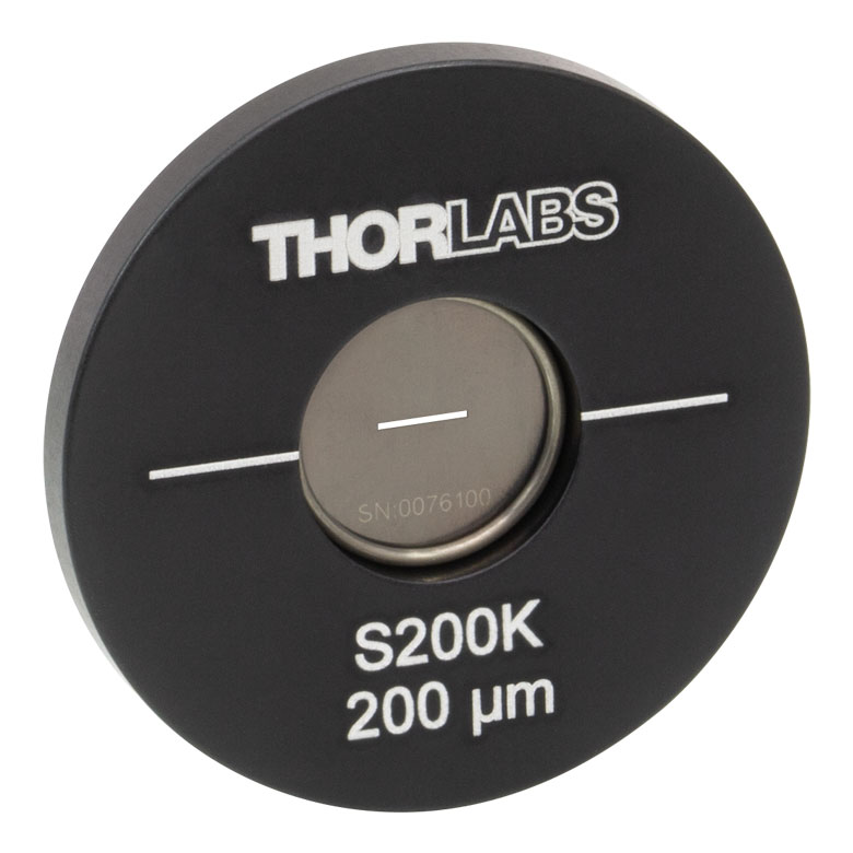 |
Slits in Stainless Steel Foils | 3 mm Slit Lengths: 5 to 500 µm Widths 10 mm Slit Lengths: 20 to 500 µm Widths |
 |
Double Slits in Stainless Steel Foils | 3 mm Slit Lengths with 40, 50, or 100 µm Widths, Spacing of 3X or 6X the Slit Width |
|
| Half-Apertures |  |
Mounted, Half-Aperture Foils | Half-Apertures for Knife-Edge Scan Measurements |
| Annular Apertures | 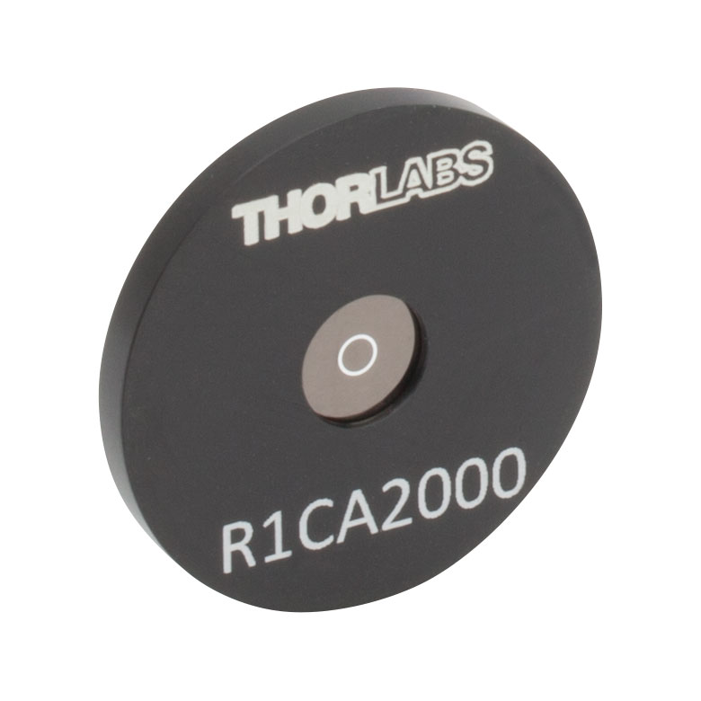 |
Annular Aperture Obstruction Targets on Quartz Substrates with Chrome Masks |
Ø1 mm Apertures with ε Ratiosb from 0.05 to 0.85 Ø2 mm Aperture with ε Ratiob of 0.85 |
| Pinhole Wheels | 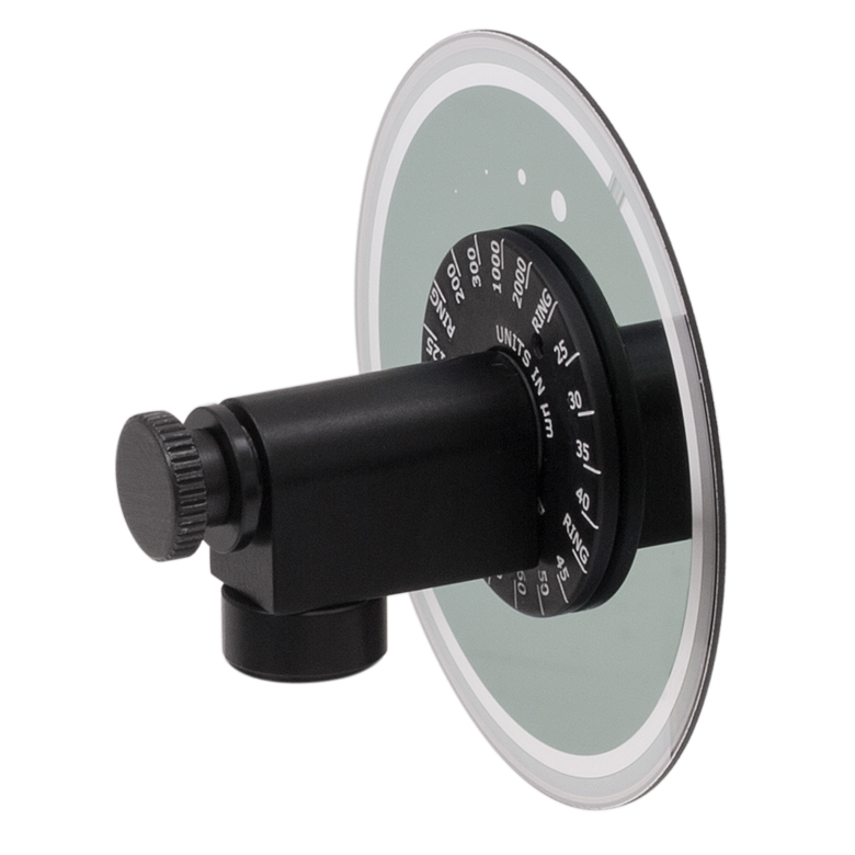 |
Manual, Mounted, Chrome-Plated Fused Silica Disks with Lithographically Etched Pinholes |
Each Disk has 16 Pinholes from Ø25 µm to Ø2 mm and Four Annular Apertures (Ø100 µm Hole, 50 µm Obstruction) |
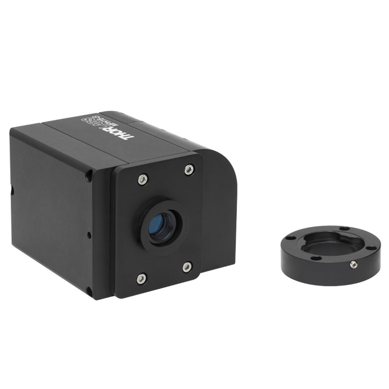 |
Motorized Pinhole Wheels with Chrome-Plated Glass Disks with Lithographically Etched Pinholes |
Each Disk has 16 Pinholes from Ø25 µm to Ø2 mm and Four Annular Apertures (Ø100 µm Hole, 50 µm Obstruction) |
|
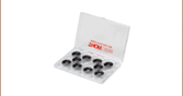
| Pinhole Kits | 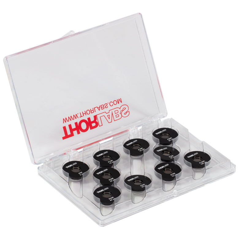 |
Stainless Steel Precision Pinhole Kits | Kits of Ten Circular Pinholes in Stainless Steel Foils Covering Ø5 µm to Ø9 mm |
| Posted Comments: | |
ILIYA SHOFMAN
(posted 2024-06-26 01:06:44.383) Hello,
I wanted to ask if there are any Thorlabs parts or general methods which can be used to attach the fixed-width slit to my optical assembly. In particular, I'd like to ensure the slit is very well horizontal with the axis of my camera, but there are no mounting/ alignment features on the slit itself. The variable slit (which is compatible with a cage mount system) is undesirable for other reasons.
Thank you! ksosnowski
(posted 2024-06-27 04:32:55.0) Hello Iliya, thanks for reaching out to Thorlabs. Typically, a rotation mount will be used to control the orientation of the slit axis. We offer CLR1 as an option to rotate optics in-line with fixed optic tubes at either end, or a mount like LRM1 could be used on one end of a fixed optic tube section. I have reached out directly to discuss your application in further detail. user
(posted 2024-05-15 06:25:34.54) Could you please provide a reflectance estimate for wavelengths in the 10µm regime? cdolbashian
(posted 2024-06-18 12:42:59.0) Thank you for reaching out to us with this inquiry. At this time, we do not have an estimate for the reflectance from this surface at 10µm. 靖家 顏
(posted 2024-02-06 11:00:46.963) 想請問你們這個1吋的slit 建議使用哪項產品來當作他的底座 可以調整也可以固定的 jdelia
(posted 2024-02-09 08:51:38.0) Thank you for contacting Thorlabs. The S15K is 1" in diameter so you can mount it in an SM1-threaded mount. I have reached out to you directly to discuss your application. Andrew Klug
(posted 2024-01-04 15:08:26.62) Your slits work well, but we're using them for very high-precision measurements, and the reflectivity of the foil of all of the slit optics are sadly too high, so we had to paint them darker as best we could. Would it be possible to offer very high absorption 5um slits similar to the blackened slits offered by Acktar? https://www.edmundoptics.com/f/acktar-blackened-air-slits/39493/
Thank you jpolaris
(posted 2024-01-04 06:48:38.0) Thank you for contacting Thorlabs. Requests for customizations can be made by contacting us at techsupport@thorlabs.com. I have reached out to you directly to discuss the feasibility of your request. Francesco Leone
(posted 2020-08-07 03:38:37.0) Hi
I'd like to know if your slits can be used in vacuum or if you have and hoc product.
Thanks
Francesco nbayconich
(posted 2020-08-07 02:39:53.0) Thank you for contacting Thorlabs. These slits are not vacuum compatible, I will reach out to you directly to discuss other alternatives. user
(posted 2019-08-15 01:55:38.38) I read in the comments that you can provide slits longer than your standard 3mm; could you make a custom slit 13mm long, with a 5um opening? And 16mm long with the same 5um opening? How straight can the line be? All would be mounted in an SM1 tube. How much would it cost? YLohia
(posted 2019-08-15 10:48:03.0) Hello, thank you for contacting Thorlabs. Custom items can be requested by emailing us at techsupport@thorlabs.com. We will reach out to you directly to discuss the possibility of offering this. taeshinkim0426
(posted 2017-08-25 10:29:49.053) Hi, I'm interested in the double slit and triple slit. 50 µm slits: 150 µm Spacing (Center to Center) Please contact me. thanks. nbayconich
(posted 2017-08-29 08:04:35.0) Thank you for contacting Thorlabs. I will reach out to you directly with a quote. chiwon.lee
(posted 2017-05-24 20:38:06.847) Hi, I need an unmounted 5 um wide slit made of just stainless steel without oxide, to make it conductive. Please contact me. Thanks nbayconich
(posted 2017-06-06 09:06:51.0) Thank you for contacting Thorlabs. We can provide a 5 µm slit without the black oxide finish. A Techsupport representative will contact you directly with more information. piet.de.vries
(posted 2016-11-22 10:44:13.87) To be able to decide if we can use the S150R I need to know more on the black oxide coating of the part. Specifically what is the type of black oxide used ? is it copper based (low Temperature blacking process) or high T Feoxide process. Could you sent additional info perhaps please ?
Thank you . tfrisch
(posted 2016-11-29 04:17:52.0) Hello, I will contact you directly about the black oxide process. thomas.hutterer
(posted 2014-06-11 14:34:16.987) Hi,
I would like to know if I could buy a slit without the mount,
And if not, if it is possible to get the slit out of the mount by myself
Regards
Thomas Hutterer jlow
(posted 2014-06-11 10:36:32.0) Response from Jeremy at Thorlabs: We can provide these slits unmounted. You can also take the slit out of the mount easily by using a good pair of tweezers and carefully pulling out the split end retaining ring. cdaly
(posted 2012-12-05 17:44:00.0) Response from Chris at Thorlabs: Thank you for using our feedback. In this case, the slit you need would be a custom item, but one that I believe we can quote for you. I will contact you directly to discuss this further. eric
(posted 2012-12-05 23:39:44.82) I'm interested in getting 50 µm vertical slit that is unmounted and does not have the black oxide coating. Could you let me know if it is possible to get this custom part, and if so send me a quote? Thank you. jlow
(posted 2012-11-12 17:05:00.0) Response from Jeremy at Thorlabs: We could supply the mounted slits and pinholes with Ø1/2" outer diameter as a custom. I will get in contact with you directly regarding this. acable
(posted 2012-11-08 14:17:43.457) Is it possible to get these in a 1/2" diameter mount. tcohen
(posted 2012-06-12 14:10:00.0) Response from Tim at Thorlabs to Karsten: Thank you for contacting us! Although the housing is 1” diameter, the diameter of the standard unmounted slit is 9.5mm. To accommodate your 13mm requirement we will need to discuss your desired specifications. I will contact you directly to continue this conversation. karsten.sperlich
(posted 2012-06-12 11:00:24.0) Dear Thorlabs team,
I need a 13 µm slit which is 14 mm tall. The S15R with 15 µm would be OK, but the height needs to be at least 13 mm. Furthermore I could use 20 µm, 25 µm and 30 µm. Each at least 13 mm long.
If that is possible please send me a quote for these slits.
Thanks in advance and best regards,
Karsten tcohen
(posted 2012-04-03 12:23:00.0) Response from Tim at Thorlabs: We should be able to provide this custom slit for you. I have contacted you directly to get more information. Simone.Rupp
(posted 2012-04-03 10:29:28.0) Dear Thorlabs team,
is it possible to get a 50µm or 100µm slit that is 6mm tall (instead of the offered 3mm)? If yes, could you contact me with a quote? Thanks! jjurado
(posted 2011-08-29 09:28:00.0) Response from Javier at Thorlabs to rmartin: Thank you very much for your feedback! We will review the design of our vertical slits and will let you know if we add this change. rmartin
(posted 2011-08-22 13:56:50.0) I have used your fixed vertical slits for spectroscopy and thought after many hours of assembly that if your slit discs had a small hole or dimple (on either side) on the aluminum substrate just inside the area taken up by the retaining ring it would make adjusting it to the opto-mechanical axes (vertical or horizontal) far easier. It would also allow the slit to be held in place while the retaining ring was tightened. Just a suggestion. apalmentieri
(posted 2010-03-25 11:01:37.0) A response from Adam at Thorlabs to Vitali: We can offer this quotation. I will contact you directly with a quote and instructions for ordering from South Korea. yahtoug
(posted 2010-03-25 10:20:25.0) Please, send me quotation for the customized versions:
Two pieces of S100R modified to housing Ø 0.5".
Two pieces of S150R modified to housing Ø 0.5".
Please, advise how to order from South Korea. Thank you. Vitali. yahtoug
(posted 2010-03-25 10:07:08.0) Please, send me quotation for the customized versions:
Two pieces of S100R modified to Ø 0.5".
Two pieces of S150R also modified to Ø 0.5".
Please, advise how to order from South Korea. A lot of thanks. Vitali. jens
(posted 2010-02-11 17:41:59.0) A reply from Jens at Thorlabs: yes, we can offer custom versions including unmounted versions. I will contact you regarding the details required for the quote. wikszak
(posted 2010-02-11 17:07:05.0) Is it possible to get umounted slits ? That would fit with the diameter of my application...
Thanks ! james.harrison
(posted 2008-07-04 08:28:33.0) Dear Sir/Madame
I need to be able to mount an S125R within a 0.5" diameter lens tube, as I have very limited space requirements. Would it be possible to provide me just with the aperature disk to perhaps allow me to mount it within an LMR adapter?
Many thanks,
James technicalmarketing
(posted 2007-12-27 12:29:00.0) Thank you for pointing out that the specifications for the slits needed clarification. This has been done. acable
(posted 2007-12-21 12:06:42.0) Please indicate the slit hieght and clean up what you mean by diameter. It is given as 3/8" and 1", just need to note mounted versus unmounted. |

 Zoom
Zoom
Click to Enlarge
Dimensions for Mounted Stainless Steel Slits in Ø1/2" Housings
- Optical Slits with Widths from 5 to 500 µm
- 3 mm Slit Length
- Stainless Steel Foils have a Black-Oxide Conversion Coating on Both Sides for Increased Absorbance
- Slits with Widths ≤40 µm Include a Recessed Counterbore to Optimize Signal Strength
- Black-Anodized Aluminum Housing:
- 1/2" Outer Diameter, 0.10" Thick
- Includes Engraved Horizontal Lines on the Front Face to Facilitate Slit Alignment
These mounted optical slits are available with slit widths from 5 to 500 µm. These slits are fabricated from stainless steel foils that have a black-oxide conversion coating on both sides. The foils are mounted in Ø1/2", 0.10" (2.5 mm) thick aluminum housings that are black-anodized. The front face of the housings are engraved with the slit item #, slit width, and horizontal lines to aid with slit alignment.
Our Ø1/2" mounted optical slits with widths of ≤40 µm have a recessed counterbore in order to thin down material around the slit. This makes the edges sharper, thus optimizing signal strength.
The slits can be taken out of their housings by removing the retaining ring using small tweezers or pliers; use care as the foil is very thin (50 µm).
| Item # | Slit Width | Tolerance | Slit Length | Foil Thickness | Foil Diameter | Foil Material | Housing Material |
|---|---|---|---|---|---|---|---|
| S5HK | 5 µm | ±1 µm | 3 mm | 50 µm | 0.38" (9.6 mm) |
300 Series Stainless Steel, Black-Oxide Conversion Coating |
6061-T6 Aluminum |
| S10HK | 10 µm | ||||||
| S15HK | 15 µm | ±1.5 µm | |||||
| S20HK | 20 µm | ±2 µm | |||||
| S30HK | 30 µm | ||||||
| S40HK | 40 µm | ±3 µm | |||||
| S50HK | 50 µm | ||||||
| S100HK | 100 µm | ±4 µm | |||||
| S150HK | 150 µm | ||||||
| S200HK | 200 µm | ||||||
| S500HK | 500 µm | ±10 µm |

 Zoom
Zoom
Click to Enlarge
Dimensions for Mounted Stainless Steel Slits in Ø1" Housings
- Optical Slits with Widths from 5 to 500 µm
- 3 mm Slit Length
- Stainless Steel Foils have a Black-Oxide Conversion Coating on Both Sides for Increased Absorbance
- Slits with Widths ≤40 μm Include a Recessed Counterbore to Optimize Signal Strength
- Black-Anodized Aluminum Housing:
- 1" Outer Diameter, 0.10" Thick
- Includes Engraved Horizontal Lines on the Front Face to Facilitate Slit Alignment
These mounted optical slits are available with slit widths from 5 to 500 µm. These slits are fabricated from stainless steel foils that have a black-oxide conversion coating on both sides. The foils are mounted in Ø1", 0.10" (2.5 mm) thick aluminum housings that are black-anodized. The front face of the housings are engraved with the slit item #, slit width, and horizontal lines to aid with slit alignment.
Our Ø1" mounted optical slits with widths ≤40 μm have a recessed counterbore in order to thin down material around the slit. This makes the edges sharper, thus optimizing signal strength.
The slits can be taken out of their housings by removing the retaining ring using small tweezers or pliers; use care as the foil is very thin (50 µm).
| Item # | Slit Width | Tolerance | Slit Length | Foil Thickness | Foil Diameter | Foil Material | Housing Material |
|---|---|---|---|---|---|---|---|
| S5K | 5 µm | ±1 µm | 3 mm | 50 µm | 0.38" (9.6 mm) |
300 Series Stainless Steel, Black-Oxide Conversion Coating |
6061-T6 Aluminum |
| S10K | 10 µm | ||||||
| S15K | 15 µm | ±1.5 µm | |||||
| S20K | 20 µm | ±2 µm | |||||
| S30K | 30 µm | ||||||
| S40K | 40 µm | ±3 µm | |||||
| S50K | 50 µm | ||||||
| S100K | 100 µm | ±4 µm | |||||
| S150K | 150 µm | ||||||
| S200K | 200 µm | ||||||
| S500K | 500 µm | ±10 µm |

 Zoom
Zoom- Optical Slits with Widths from 20 to 500 µm
- 10 mm Slit Lengths
- Stainless Steel Foils have a Black-Oxide Conversion Coating on Both Sides for Increased Absorbance
- Slits with Widths ≤40 µm Include a Recessed Counterbore to Optimize Signal Strength
These unmounted optical slits are available with slit widths from 20 to 500 µm. These slits are fabricated from stainless steel foils that have a black-oxide conversion coating on both sides.
Our optical slits in unmounted Ø1/2" foils with widths of ≤40 µm have a recessed counterbore in order to thin down material around the slit. This makes the edges sharper, thus optimizing signal strength.
When handling the slits, please use small tweezers or pliers; use care as the foil is very thin (50 µm). These pinholes can be mounted in our SM05-Threaded Lens Tubes, secured between two retaining rings.
| Item # | Slit Width | Tolerance | Slit Length | Foil Thickness | Foil Diameter | Foil Material |
|---|---|---|---|---|---|---|
| S20ULK | 20 µm | ±2 µm | 10 mm | 50 µm | 1/2" (12.7 mm) |
300 Series Stainless Steel, Black-Oxide Conversion Coating |
| S30ULK | 30 µm | |||||
| S40ULK | 40 µm | ±3 µm | ||||
| S50ULK | 50 µm | |||||
| S100ULK | 100 µm | ±4 µm | ||||
| S150ULK | 150 µm | |||||
| S200ULK | 200 µm | |||||
| S500ULK | 500 µm | ±10 µm |

 Zoom
Zoom
Click to Enlarge
Dimensions for Mounted Stainless Steel Slits in Ø1" Housings
- Optical Slits with Widths from 20 to 500 µm
- 10 mm Slit Lengths
- Stainless Steel Foils have a Black-Oxide Conversion Coating on Both Sides for Increased Absorbance
- Slits with Widths ≤40 μm Include a Recessed Counterbore to Optimize Signal Strength
- Black-Anodized Aluminum Housing:
- 1" Outer Diameter, 0.10" Thick
- Includes Engraved Horizontal Lines on the Front Face to Facilitate Slit Alignment
These mounted optical slits are available with slit widths from 20 to 500 µm. These slits are fabricated from stainless steel foils that have a black-oxide conversion coating on both sides. The foils are mounted in Ø1", 0.10" (2.5 mm) thick aluminum housings that are black-anodized. The front face of the housings are engraved with the slit item #, slit width, and horizontal lines to aid with slit alignment.
Our Ø1" mounted optical slits with widths ≤40 μm have a recessed counterbore in order to thin down material around the slit. This makes the edges sharper, thus optimizing signal strength.
The slits can be taken out of their housings by removing the retaining ring using small tweezers or pliers; use care as the foil is very thin (50 µm).
| Item # | Slit Width | Tolerance | Slit Length | Foil Thickness | Foil Diameter | Foil Material | Housing Material |
|---|---|---|---|---|---|---|---|
| S20LK | 20 µm | ±2 µm | 10 mm | 50 µm | 1/2" (12.7 mm) |
300 Series Stainless Steel, Black-Oxide Conversion Coating |
6061-T6 Aluminum |
| S30LK | 30 µm | ||||||
| S40LK | 40 µm | ±3 µm | |||||
| S50LK | 50 µm | ||||||
| S100LK | 100 µm | ±4 µm | |||||
| S150LK | 150 µm | ||||||
| S200LK | 200 µm | ||||||
| S500LK | 500 µm | ±10 µm |