 Products Home / Optomechanical Components / Irises / Apertures / Precision Pinholes / Circular Precision Pinholes, Stainless Steel Foils
Circular Precision Pinholes, Stainless Steel Foils

- Pinhole Sizes from Ø1 μm to Ø9 mm
- Stainless Steel Foils
- Blackened for Increased Absorbance on Both Sides
- Available Unmounted or in Aluminum Housings
P20K
Ø20 µm Pinhole,
Ø1" Housing
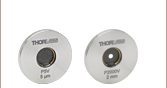
P5000UK
Ø5 mm Pinhole,
Ø1/2" Foil
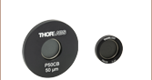
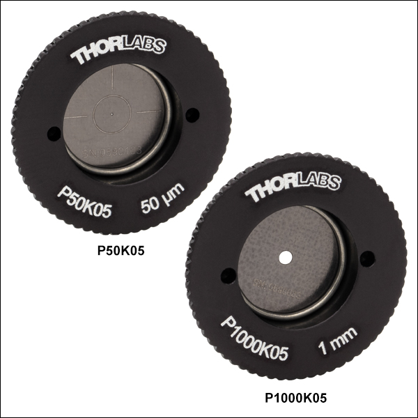
P50K05
Ø50 μm Pinhole,
SM05-Threaded Housing
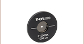
P1000K1
Ø1 mm Pinhole,
SM1-Threaded Housing
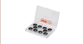
PKIT4K
Pinhole Kit,
Ø2 mm - Ø9 mm
(Not to Scale)
P1000HK
Ø1 mm Pinhole,
Ø1/2" Housing


Please Wait
| Apertures Selection Guide |
|---|
| Single Precision Pinholes |
| Circular in Stainless Steel Foils |
| Circular in Stainless Steel Foils, Vacuum Compatible |
| Circular in Gold-Plated Copper Foils |
| Circular in Tungsten Foils |
| Circular in Molybdenum Foils |
| Square in Stainless Steel Foils |
| Pinhole Kits |
| Pinhole Wheels |
| Manual |
| Motorized |
| Pinhole Spatial Filter |
| Slits |
| Annular Apertures |
| Alignment Tools |
Features
- Precision Pinholes in Stainless Steel Foils Available Unmounted or Mounted in Aluminum Housings
- Ø2.5 mm to Ø9 mm Pinholes in Unmounted Ø1/2" Foils
- Ø1 µm to Ø2 mm Pinholes with Ø1/2" Housings
- Ø50 µm to Ø1 mm Pinholes with SM05-Threaded (0.535"-40) Housings
- Ø1 µm to Ø9 mm Pinholes with Ø1" Housings
- Ø50 µm to Ø1 mm Pinholes with SM1-Threaded (1.035"-40) Housings
- Blackened for Increased Absorbance on Both Sides
- Stainless Steel Foils in Ø1/2" or Ø1" Housings Available in Kits of Ten
- Contact Tech Support to Discuss Custom Options
Single precision pinholes offer optical apertures for applications such as alignment, beam conditioning, and imaging. The Ø1 µm to Ø9 mm pinholes below are in blackened stainless steel foils, with select sizes available unmounted or mounted in black-anodized aluminum housings (Ø1/2", SM05 threaded, Ø1", or SM1 threaded). Our stainless steel pinholes mounted in Ø1/2" or Ø1"unthreaded housings are also available in kits. We offer pinholes with a variety of other foil materials; see the table to the right for options.
For many applications, such as holography, spatial intensity variations in the laser beam are unacceptable. Using precision pinholes in conjunction with positioning and focusing equipment such as our KT311(/M) Spatial Filter System creates a "noise" filter, effectively stripping variations in intensity out of a Gaussian beam. Please see the Tutorial tab for more information on spatial filters.
Precision Pinhole Options
Thorlabs' precision pinholes are available with an assortment of fabrication materials and coatings. The choice of a particular size and material should depend on the application. Low-power applications may benefit more from the absorbance of our blackened stainless steel foils, which are offered in anodized-aluminum housings, or our stainless steel foils with a black PVD coating, which are offered in vacuum-compatible stainless steel housings. High-power applications may need the high damage threshold and reflectance of gold-plated copper foils, the high melting point and lower reflectance of our tungsten foils, or the high melting point of our molybdenum foils paired with the low reflectance (4% @ 800 nm) of their black-coated front side. Please see the Foil Comparison and Graph tabs for more information.
In addition to single pinholes, Thorlabs also offers pinhole wheels that contain 16 radially-spaced pinholes that are lithographically etched onto a chrome-plated fused silica substrate. These wheels allow the user to test multiple pinhole sizes within a setup.
If you do not see what you need among our pinhole offerings, it is possible to special order pinholes that are fabricated from different substrate materials, have different pinhole sizes, incorporate multiple holes in one foil, or provide different pinhole configurations. Customized pinhole housings are also available. Please contact Tech Support to discuss your specific needs.
| Precision Pinhole and Optical Slit Selection Guide | |||||
|---|---|---|---|---|---|
| Material | Product | ||||
| Blackened Stainless Steel | Circular Precision Pinholes | ||||
| Square Precision Pinholes | |||||
| Optical Slits | |||||
| Stainless Steel with PVD Black Coating |
Circular Precision Pinholes | ||||
| Gold-Plated Copper Foil (Rear) and PVD Black Coating (Front) |
Circular Precision Pinholes | ||||
| Tungsten Foil | Circular Precision Pinholes | ||||
| Molybdenum Foil (Rear) and Absorptive Polymer Coating (Front) |
Circular Precision Pinholes | ||||
Precision Pinholes and Slits
Thorlabs offers precision pinholes with blackened stainless steel, gold-plated copper, tungsten, or molybdenum foils. Our pinholes with stainless steel foils are blackened on both sides for increased absorbance and are available from stock in circles from Ø1 µm to Ø9 mm and squares from 100 µm x 100 µm to 1 mm x 1 mm. Our stainless steel pinholes with a black PVD coating are vacuum compatible and available in 5 μm to 2 mm diameters. Our pinholes with gold-plated copper foils, plated with gold on one side and black PVD coated on the reverse, are available with pinhole diameters from 5 µm to 2 mm. Our pinholes with tungsten foils are uncoated and available with pinhole diameters from 5 µm to 2 mm. Lastly, our pinholes with molybdenum foils have an absorptive polymer coating on the front sides and are available with pinhole diameters from 5 µm to 2 mm. We also offer slits in blackened stainless steel foils from stock with slit widths from 5 to 200 µm.
If you do not see what you need among our stock pinhole and slit offerings, it is also possible to special order pinholes and slits that are made with different foil materials, have different hole sizes and shapes, incorporatoles in one foil, or provide different hole configurations. Please contact Tech Support to discuss your specific needs. For more information on the properties of the bulk materials from which the pinholes are fabricated, see the table below.
Material Properties
Depending on the application, it can be important to consider the material properties of the pinhole or slit. The material used to construct the aperture can have varying levels of melting point, density, and thermal conductivity, as detailed in the table below.
| Material Properties | ||||
|---|---|---|---|---|
| Material | 300 Series Stainless Steela | Copperb | Tungsten | Molybdenumc |
| Melting Point | 1390 - 1450 °C | 1085 °C | 3422 °C | 2623 °C |
| Density | 8.03 g/cm3 | 8.96 g/cm3 | 19.25 g/cm3 | 10.28 g/cm3 |
| Brinell Hardness | 170 MPa | 878 MPa | 2570 MPa | 1500 MPa |
| Damage Thresholdd (10 ns Pulse, 1 kHz @ 355 nm) | 1.54 MW/mm2 | 4.82 MW/mm2 | 9.39 MW/mm2 | 6.34 MW/mm2 |
| Thermal Expansion Coefficient | 16.2 (µm/m)/°C | 16.7 (µm/m)/°C | 4.5 (µm/m)/°C | 5.0 (µm/m)/°C |
| Specific Heat @ 20 °C | 485 J/(K*kg) | 385 J/(K*kg) | 134 J/(K*kg) | 250 J/(K*kg) |
| Thermal Conductivity | 16.2 W/(m*K) | 401 W/(m*K) | 173 W/(m*K) | 138 W/(m*K) |
| Thermal Diffusivity @ 300 K | 3.1 mm2/s | 111 mm2/s | 80 mm2/s | 54.3 mm2/s |
Reflectance
The reflectance of the foil material or coating affects performance in a variety of applications. Below is presented a reflectance graph for all the materials and coatings that are offered with our circular and square precision pinholes, as well as our mounted optical slits. The raw reflectance data can be found here.
It is important to note that the front of the gold-plated copper foil circular precision pinholes have a low-reflectance PVD black coating. The rear of these pinholes leaves the gold-plated copper foil bare. This also occurs on the molybdenum foil circular precision pinholes, which have a low-reflectance absorptive polymer coating on the front and the molybdenum foil is left bare on the back.
Reflectance Graph
Below is a reflectance graph for the blackened stainless steel foils used in the circular precision pinholes. The raw reflectance data can be found here.
Principles of Spatial Filters
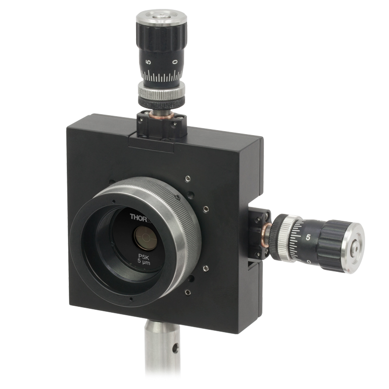
For many applications, such as holography, spatial intensity variations in the laser beam are unacceptable. Our KT311 spatial filter system is ideal for producing a clean Gaussian beam.
Figure 1: Spatial Filter System
The input Gaussian beam has spatially varying intensity "noise". When a beam is focused by an aspheric lens, the input beam is transformed into a central Gaussian spot (on the optical axis) and side fringes, which represent the unwanted "noise" (see Figure 2 below). The radial position of the side fringes is proportional to the spatial frequency of the "noise".
Figure 2
By centering a pinhole on a central Gaussian spot, the "clean" portion of the beam can pass while the "noise" fringes are blocked (see Figure 3 below).
Figure 3
The diffraction-limited spot size at the 99% contour is given by:

where λ = wavelength, ƒ=focal length and r = input beam radius at the 1/e2 point.
Choosing the Correct Optics and Pinhole for Your Spatial Filter System
The correct optics and pinhole for your application depend on the input wavelength, source beam diameter, and desired exit beam diameter.
For example, suppose that you are using a 650 nm diode laser source that has a diameter (1/e2) of 1.2 mm and want your beam exiting the spatial filter system to be about 4.4 mm in diameter. Based on these parameters, the C560TME-B mounted aspheric lens would be an appropriate choice for the input side of spatial filter system because it is designed for use at 650 nm, and its clear aperture measures 5.1 mm, which is large enough to accommodate the entire diameter of the laser source.
The equation for diffraction limited spot size at the 99% contour is given above, and for this example, λ = (650 x 10-9 m), f = 13.86 mm for the C560TM-B, and r = 0.6 mm. Substitution yields
Diffraction-Limited Spot Size (650 nm source, Ø1.2 mm beam)
The pinhole should be chosen so that it is approximately 30% larger than D. If the pinhole is too small, the beam will be clipped, but if it is too large, more than the TEM00 mode will get through the pinhole. Therefore, for this example, the pinhole should ideally be 19.5 microns. Hence, we would recommend the mounted pinhole P20D, which has a pinhole size of 20 μm. Parameters that can be changed to alter the beam waist diameter, and thus the pinhole size required, include changing the input beam diameter and focal length of focusing lens. Decreasing the input beam diameter will increase the beam waist diameter. Using a longer focal length focusing lens will also increase the beam waist diameter.
Finally, we need to choose the optic on the output side of the spatial filter so that the collimated beam's diameter is the desired 4.4 mm. To determine the correct focal length for the lens, consider the following diagram in Figure 4, which is not drawn to scale. From the triangle on the left-hand side, the angle is determined to be approximately 2.48o. Using this same angle for the triangle on the right-hand side, the focal length for the plano-convex lens should be approximately 50 mm.
Figure 4: Beam Expansion Example
For this focal length, we recommend the LA1131-B plano-convex lens [with f = 50 mm at the design wavelength (λ = 633 nm), this is still a good approximation for f at the source wavelength (λ = 650 nm)].
Note: The beam expansion equals the focal length of the output side divided by the focal length of the input side.
For optimal performance, a large-diameter aspheric lens can be used in place of a plano-convex lens if the necessary focal length on the output side is 20 mm (see AL2520-A, AL2520-B, AL2520-C). These lenses are 25 mm in diameter and can be held in place using the supplied SM1RR Retaining Ring.
Click to Enlarge
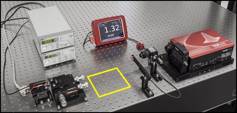
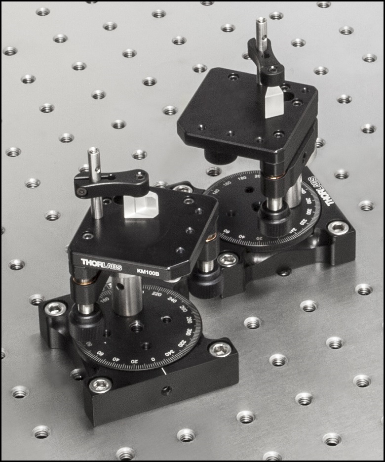
Figure 1: The beam circularization systems were placed in the area of the experimental setup highlighted by the yellow rectangle.

Click to Enlarge
Figure 4: Spatial Filter System
Click to Enlarge
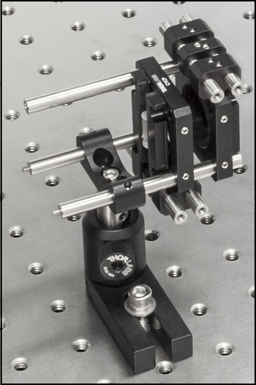
Figure 3: Anamorphic Prism Pair System
Click to Enlarge
Figure 2: Cylindrical Lens Pair System
Comparison of Circularization Techniques for Elliptical Beams
Edge-emitting laser diodes emit elliptical beams as a consequence of the rectangular cross sections of their emission apertures. The component of the beam corresponding to the narrower dimension of the aperture has a greater divergence angle than the orthogonal beam component. As one component diverges more rapidly than the other, the beam shape is elliptical rather than circular.
Elliptical beam shapes can be undesirable, as the spot size of the focused beam is larger than if the beam were circular, and as larger spot sizes have lower irradiances (power per area). Techniques for circularizing an elliptical beam include those based on a pair of cylindrical lenses, an anamorphic prism pair, or a spatial filter. This work investigated all three approaches. The characteristics of the circularized beams were evaluated by performing M2 measurements, wavefront measurements, and measuring the transmitted power.
While it was demonstrated that each circularization technique improves the circularity of the elliptical input beam, each technique was shown to provide a different balance of circularization, beam quality, and transmitted power. The results of this work, which are documented in this Lab Fact, indicate that an application's specific requirements will determine which is the best circularization technique to choose.
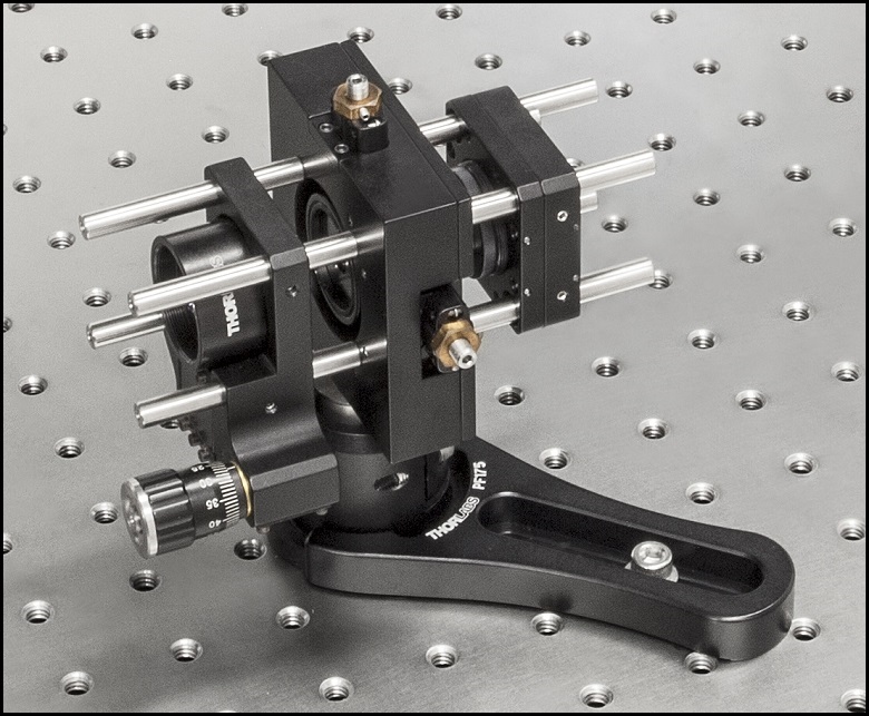
Experimental Design and Setup
The experimental setup is shown in Figure 1. The elliptically-shaped, collimated beam of a temperature-stabilized 670 nm laser diode was input to each of our circularization systems shown in Figures 2 through 4. Collimation results in a low-divergence beam, but it does not affect the beam shape. Each system was based on one of the following:
- LJ1874L2-A and LJ1638L1-A Plano-Convex Convex Cylindrical Lenses (Figure 2)
- PS873-A Unmounted Anamorphic Prism Pair (Figure 3)
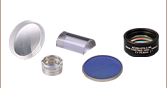
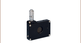
- Previous Generation KT310 Spatial Filter System with P5S Ø5 µm Pinhole (Figure 4)
The beam circularization systems, shown to the right, were placed, one at a time, in the vacant spot in the setup highlighted by the yellow rectangle. With this arrangement, it was possible to use the same experimental conditions when evaluating each circularization technique, which allowed the performance of each to be directly compared with the others. This experimental constraint required the use of fixturing that was not optimally compact, as well as the use of an unmounted anamorphic prism pair, instead of a more convenient mounted and pre-aligned anamorphic prism pair.
The characteristics of the beams output by the different circularization systems were evaluated by making measurements using a power meter, a wavefront sensor, and an M2 system. In the image of the experimental setup, all of these systems are shown on the right side of the table for illustrative purposes; they were used one at a time. The power meter was used to determine how much the beam circularization system attenuated the intensity of the input laser beam. The wavefront sensor provided a way to measure the aberrations of the output beam. The M2 system measurement describes the resemblance of the output beam to a Gaussian beam. Ideally, the circularization systems would not attenuate or aberrate the laser beam, and they would output a perfectly Gaussian beam.
Edge-emitting laser diodes also emit astigmatic beams, and it can be desirable to force the displaced focal points of the orthogonal beam components to overlap. Of the three circularization techniques investigated in this work, only the cylindrical lens pair can also compensate for astigmatism. The displacement between the focal spots of the orthogonal beam components were measured for each circularization technique. In the case of the cylindrical lens pair, their configuration was tuned to minimize the astigmatism in the laser beam. The astigmatism was reported as a normalized quantity.
Experimental Results
The experimental results are summarized in the following table, in which the green cells identify the best result in each category. Each circularization approach has its benefits. The best circularization technique for an application is determined by the system’s requirements for beam quality, transmitted optical power, and setup constraints.
Spatial filtering significantly improved the circularity and quality of the beam, but the beam had low transmitted power. The cylindrical lens pair provided a well-circularized beam and balanced circularization and beam quality with transmitted power. In addition, the cylindrical lens pair compensated for much of the beam's astigmatism. The circularity of the beam provided by the anamorphic prism pair compared well to that of the cylindrical lens pair. The beam output from the prisms had better M2 values and less wavefront error than the cylindrical lenses, but the transmitted power was lower.
| Method | Beam Intensity Profile | Circularitya | M2 Values | RMS Wavefront | Transmitted Power | Normalized Astigmatismb |
|---|---|---|---|---|---|---|
| Collimated Source Output (No Circularization Technique) |
 Click to Enlarge Scale in Microns |
0.36 | Y Axis: 1.63 |
0.17 | Not Applicable | 0.67 |
| Cylindrical Lens Pair | 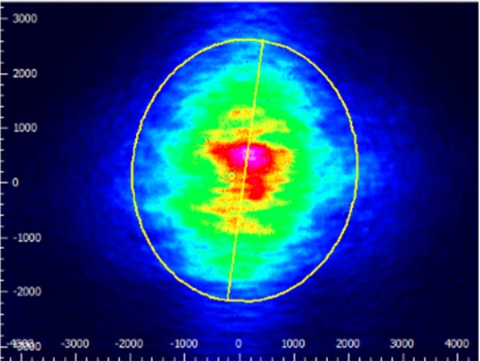 Click to Enlarge Scale in Microns |
0.84 | X Axis: 1.90 Y Axis: 1.93 |
0.30 | 91% | 0.06 |
| Anamorphic Prism Pair |
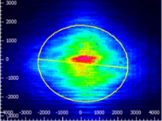 Click to Enlarge Scale in Microns |
0.82 | X Axis: 1.60 Y Axis: 1.46 |
0.16 | 80% | 1.25 |
| Spatial Filter | 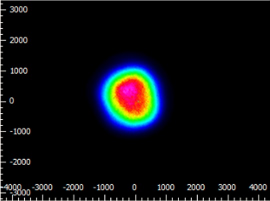 Click to Enlarge Scale in Microns |
0.93 | X Axis: 1.05 Y Axis: 1.10 |
0.10 | 34% | 0.36 |
Components used in each circularization system were chosen to allow the same experimental setup be used for all experiments. This had the desired effect of allowing the results of all circularization techniques to be directly compared; however, optimizing the setup for a circularization technique could have improved its performance. The mounts used for the collimating lens and the anamorphic prism pair enabled easy manipulation and integration into this experimental system. It is possible that using smaller mounts would improve results by allowing the members of each pair to be more precisely positioned with respect to one another. In addition, using made-to-order cylindrical lenses with customized focal lengths may have improved the results of the cylindrical lens pair circularization system. All results may have been affected by the use of the beam profiler software algorithm to determine the beam radii used in the circularity calculation.
Additional Information
Some information describing selection and configuration procedures for several components used in this experimental work can be accessed by clicking the following hyperlinks:
| Posted Comments: | |
Fabrice Del Cul
(posted 2022-03-12 03:05:46.44) Hi Thorlabs crew,
same question Eberhard posted below. In fact 50µm thickness is too large for spatial filtering application. What is the true thickness near hole edge....really 50µm?
Thank you.
Best regards jgreschler
(posted 2022-03-21 11:46:43.0) Thank you for contacting Thorlabs. The thickness of the foil is 50um over the entire surface of the pinhole, however there is some degree to which the pinhole geometry is conical. I have reached out to you directly with more information. Eberhard Riedle
(posted 2021-12-19 13:18:53.077) Dear Sirs,
inspecting some of your pinholes on a stereo microscope, we have the strong impression that the appearance is different from the two sides.
Is the "hole" cylindrical or conical? This would make the prefered direction of use significantly differing.
Unfortunately, we do not find any info on this issue on your website. Please advise!
Also, we thing the drawings of the retaining ring (cut) are erroneous.
Beste regards
Eberhard Riedle jgreschler
(posted 2021-12-30 08:39:30.0) Thank you for reaching out to Thorlabs. I have contacted you directly to discuss this further. Przemyslaw Gontar
(posted 2021-12-09 07:58:15.91) Hello, what is reflectance @ 633 nm on front side? jgreschler
(posted 2021-12-16 03:29:18.0) Thank you for reaching out to Thorlabs. The reflectance value of the black coated stainless steel at 600nm is between 15 and 20 percent. I will reach out to you directly to discuss further. Fedor Talantov
(posted 2021-06-14 13:12:03.313) Hello,
Is it possible to have a precision pinhole with a diameter of 7000 um (7mm) manufactured?
Thanks,
Fedor. YLohia
(posted 2021-06-15 11:04:41.0) Hello Fedor, custom parts can be requested by using the "Request Quote" button above. We will contact you directly to discuss the possibility of offering this. |
| Apertures Selection Guide | |||
|---|---|---|---|
| Aperture Type | Representative Image (Click to Enlarge) |
Description | Aperture Sizes Available from Stocka |
| Single Precision Pinholesa |
 |
Circular Pinholes in Stainless Steel Foils | Ø1 µm to Ø9 mm |
 |
Circular Pinholes in Stainless Steel Foils, Vacuum Compatible |
Ø5 µm to Ø2 mm | |
 |
Circular Pinholes in Gold-Plated Copper Foils | Ø5 µm to Ø2 mm | |
 |
Circular Pinholes in Tungsten Foils | Ø5 µm to Ø2 mm | |
 |
Circular Pinholes in Molybdenum Foils | Ø5 µm to Ø2 mm | |
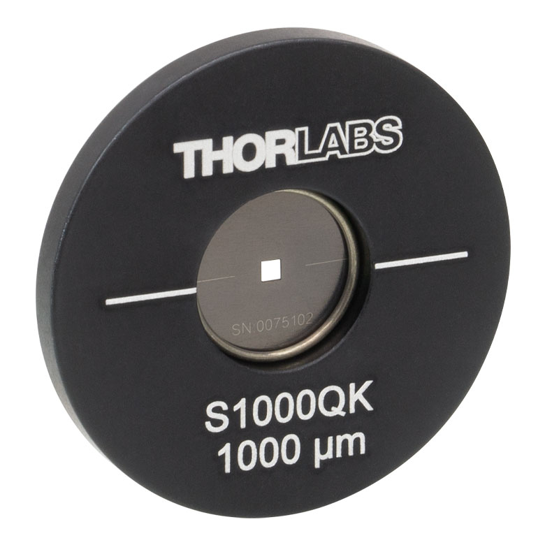 |
Square Pinholes in Stainless Steel Foils | 100 to 1000 µm Square | |
| Slitsa | 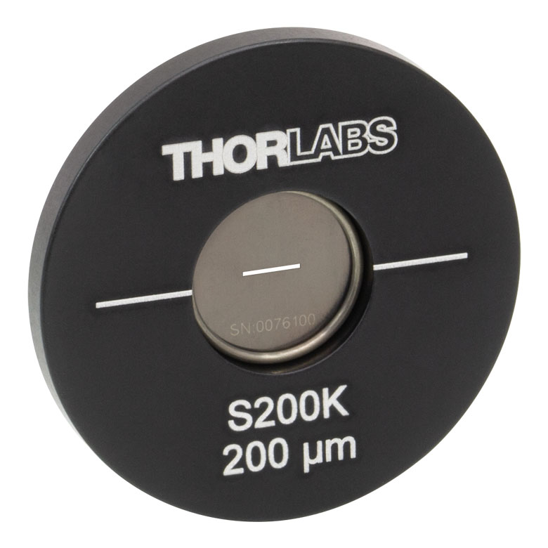 |
Slits in Stainless Steel Foils | 3 mm Slit Lengths: 5 to 200 µm Widths 10 mm Slit Lengths: 20 to 200 µm Widths |
 |
Double Slits in Stainless Steel Foils | 3 mm Slit Lengths with 40, 50, or 100 µm Widths, Spacing of 3X or 6X the Slit Width |
|
| Annular Apertures | 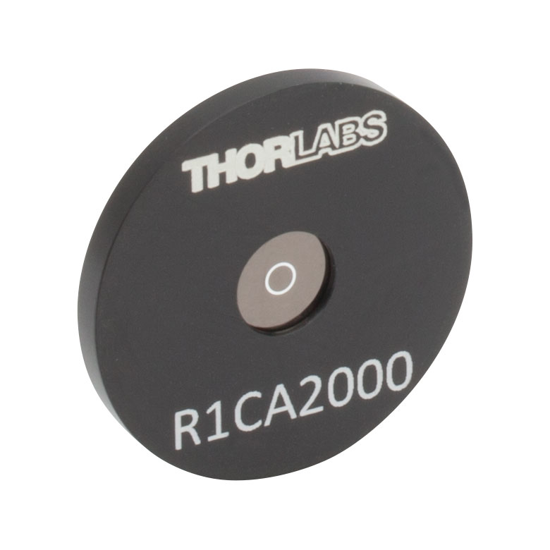 |
Annular Aperture Obstruction Targets on Quartz Substrates with Chrome Masks |
Ø1 mm Apertures with ε Ratiosb from 0.05 to 0.85 Ø2 mm Aperture with ε Ratiob of 0.85 |
| Pinhole Wheels | 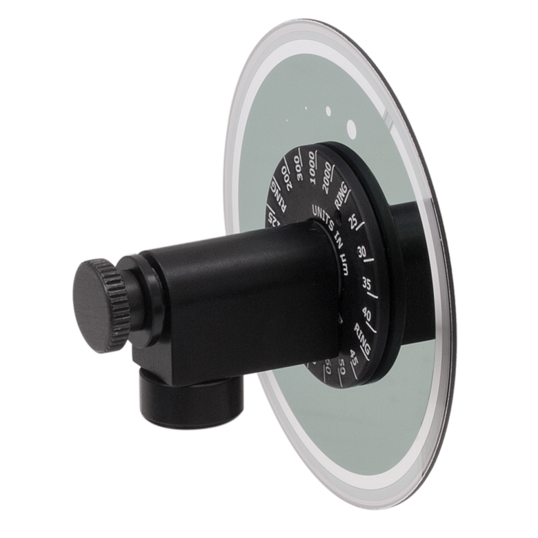 |
Manual, Mounted, Chrome-Plated Fused Silica Disks with Lithographically Etched Pinholes |
Each Disk has 16 Pinholes from Ø25 µm to Ø2 mm and Four Annular Apertures (Ø100 µm Hole, 50 µm Obstruction) |
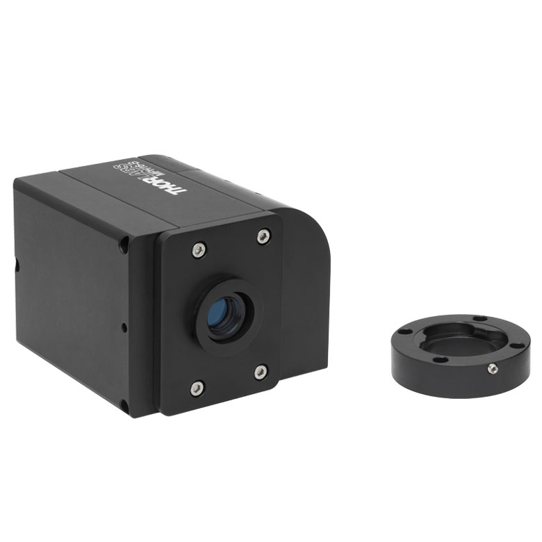 |
Motorized Pinhole Wheels with Chrome-Plated Glass Disks with Lithographically Etched Pinholes |
Each Disk has 16 Pinholes from Ø25 µm to Ø2 mm and Four Annular Apertures (Ø100 µm Hole, 50 µm Obstruction) |
|
| Pinhole Kits | 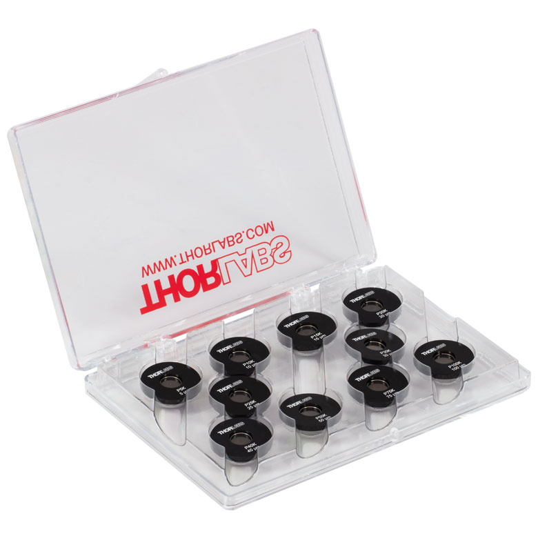 |
Stainless Steel Precision Pinhole Kits | Kits of Ten Circular Pinholes in Stainless Steel Foils Covering Ø5 µm to Ø9 mm |

 Zoom
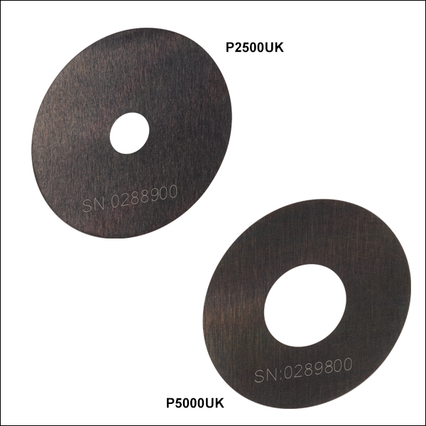
Zoom- Precision Pinholes from Ø2.5 mm to Ø9 mm
- Stainless Steel Foils are Blackened on Both Sides for Increased Absorbance
These unmounted precision pinholes are available with pinhole diameters from 2.5 mm to 9 mm. They are fabricated from stainless steel foils that are blackened on both sides. When handling the pinholes, please use small tweezers or pliers; use care as the foil is very thin (50 µm). These pinholes can be mounted in our SM05-Threaded Lens Tubes, secured between two retaining rings.
Upon request, these pinholes are available with item-specific test reports at an additional cost. Please contact Tech Support for details.
| Item # | Pinhole Diameter | Diameter Tolerance | Circularitya | Foil Thickness | Foil Material |
|---|---|---|---|---|---|
| P2500UK | 2.5 mm | ±40 µm | ≥95% | 50 µm | 300 Series Stainless Steel, Black-Oxide Conversion Coating |
| P3000UK | 3 mm | ±40 µm | |||
| P3500UKb | 3.5 mm | ±40 µm | |||
| P4000UK | 4 mm | ±50 µm | |||
| P4500UK | 4.5 mm | ±50 µm | |||
| P5000UK | 5 mm | ±50 µm | |||
| P7000UKb | 7 mm | ±80 µm | |||
| P7500UK | 7.5 mm | ±80 µm | |||
| P9000UK | 9 mm | ±80 µm |

 Zoom
Zoom
Click to Enlarge
Dimensions for Mounted Stainless Steel Pinholes in Ø1/2" (12.7 mm) Housing
Click to Enlarge
Rear of a Mounted Pinhole
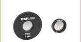
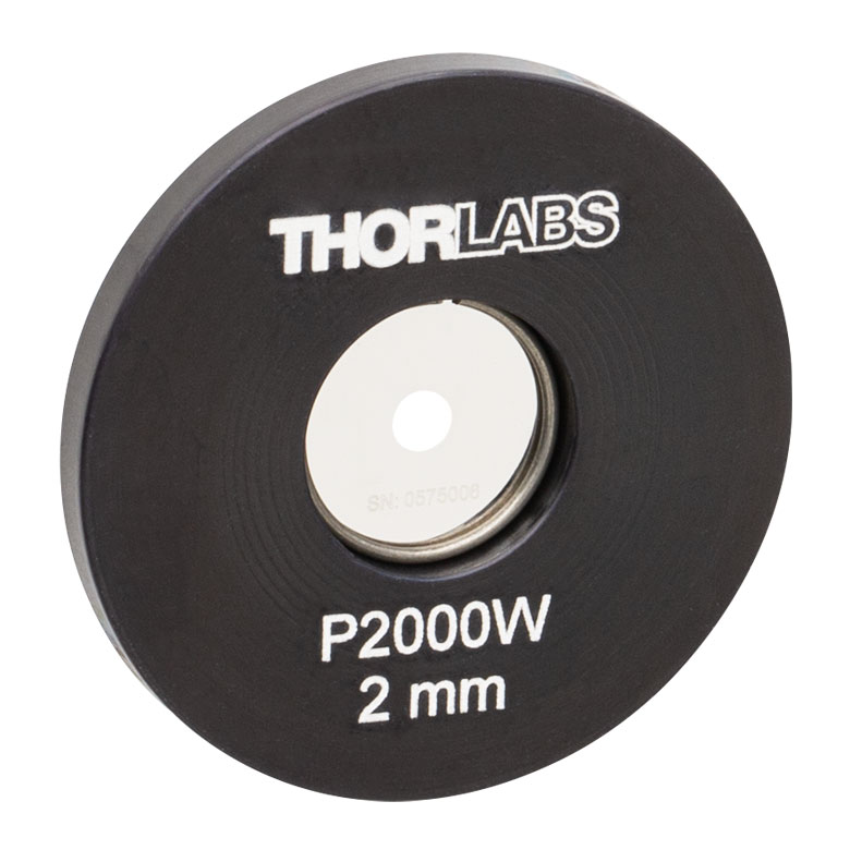
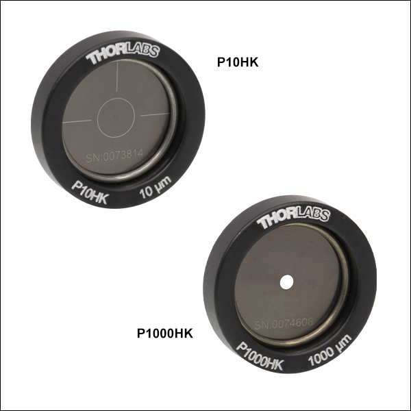
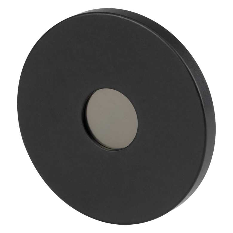
- Precision Pinholes from Ø1 µm to Ø9 mm
- Stainless Steel Foils are Blackened on Both Sides for Increased Absorbance
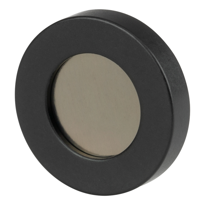
- Black-Anodized Aluminum Housings with 1/2" (12.7 mm) Outer Diameters
- Available for Individual Sale or in Kits of Ten (See Below)
These mounted precision pinholes are available with pinhole diameters from 1 µm to 2 mm. They are fabricated from stainless steel foils that are blackened on both sides. The foils are mounted in Ø1/2" (12.7 mm), 0.10" (2.5 mm) thick aluminum housings that are black-anodized. Each housing is engraved with the pinhole Item # and the size of the pinhole.
The foils can be taken out of their housings by removing the retaining ring using small tweezers or pliers; use care as the foil is very thin (50 µm).
Upon request, these pinholes are available with item-specific test reports at an additional cost. Please contact Tech Support for details.
| Item # | Pinhole Diameter | Diameter Tolerance | Circularitya | Foil Thickness | Foil Material | Housing Material |
|---|---|---|---|---|---|---|
| P1HK | 1 µm | +0.25 / -0.10 µm | ≥80% | 50 µm | 300 Series Stainless Steel, Black-Oxide Conversion Coating |
6061-T6 Aluminum |
| P2HK | 2 µm | ±0.25 µm | ||||
| P5HKb | 5 µm | ±1 µm | ≥85% | |||
| P10HKb | 10 µm | |||||
| P15HKb | 15 µm | ±1.5 µm | ||||
| P20HKb | 20 µm | ±2 µm | ||||
| P25HKb | 25 µm | ±2 µm | ≥90% | |||
| P30HKb | 30 µm | |||||
| P40HKb | 40 µm | ±3 µm | ||||
| P50HKb | 50 µm | |||||
| P75HKb | 75 µm | |||||
| P100HKb | 100 µm | ±4 µm | ≥95% | |||
| P150HKb | 150 µm | ±6 µm | ||||
| P200HKb | 200 µm | |||||
| P300HK | 300 µm | ±8 µm | ||||
| P400HK | 400 µm | ±10 µm | ||||
| P500HK | 500 µm | |||||
| P600HK | 600 µm | |||||
| P700HK | 700 µm | |||||
| P800HK | 800 µm | |||||
| P900HK | 900 µm | |||||
| P1000HKc | 1 mm | |||||
| P2000HK | 2 mm |

 Zoom
Zoom
Click to Enlarge
Dimensions for Stainless Steel Pinholes in SM05-Threaded Housings
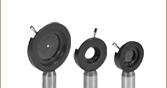
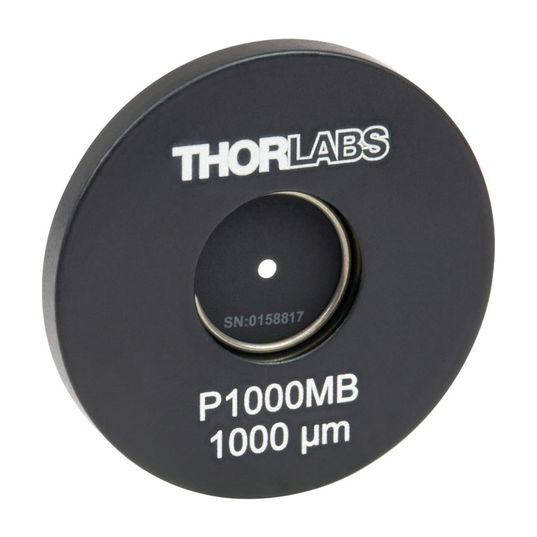
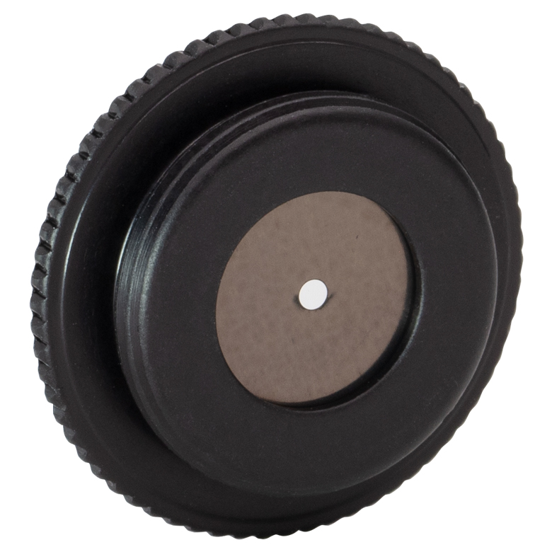
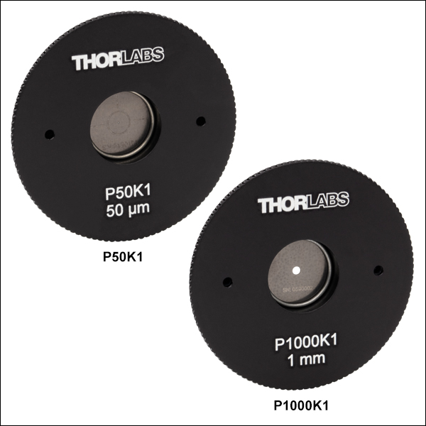
- Precision Pinholes from Ø50 µm to Ø1 mm
- Stainless Steel Foils are Blackened on Both Sides for Increased Absorbance
- Black Anodized Aluminum Housings
- 0.10" Deep SM05 (0.535"-40) Threads
- 0.70" Outer Diameter Matches that of SM05 Lens Tubes
Click to Enlarge
Rear of a Mounted Pinhole Showing the SM05 Threading
These mounted precision pinholes are available with pinhole diameters from 50 µm to 1 mm. They are fabricated from stainless steel foils that are blackened on both sides. The foils are mounted in 0.14" (3.7 mm) thick, black-anodized aluminum housings that have 0.10" (2.5 mm) deep SM05 threads. The SM05 threading of these pinholes provides direct compatibility with any internally SM05-threaded mount, while the 0.70" (17.8 mm) housing outer diameter matches that of a standard Ø1/2" lens tube. The housing has a knurled outer edge for increased grip while screwing into or unscrewing out of another part by hand. For more precise control, two holes on the front of the housing accept the SPW801 or SPW908 spanner wrench. Each housing is engraved with the pinhole Item # and the size of the pinhole.
The foils can be taken out of their housings by removing the retaining ring using small tweezers or pliers; use care as the foil is very thin (50 µm).
Upon request, these pinholes are available with item-specific test reports at an additional cost. Please contact Tech Support for details.
| Item # | Pinhole Diameter | Diameter Tolerance |
Circularitya | Foil Thickness | Foil Material | Housing Material |
|---|---|---|---|---|---|---|
| P50K05b | 50 µm | ±3 µm | ≥90% | 50 µm | 300 Series Stainless Steel, Black-Oxide Conversion Coating |
6061-T6 Aluminum |
| P100K05b | 100 µm | ±4 µm | ≥95% | |||
| P200K05b | 200 µm | ±6 µm | ||||
| P500K05 | 500 µm | ±10 µm | ||||
| P1000K05c | 1 mm |

 Zoom
Zoom
Click for Details
Dimensions for Stainless Steel Pinholes in Ø1" Housing
- Precision Pinholes from Ø1 µm to Ø9 mm
- Stainless Steel Foils are Blackened on Both Sides for Increased Absorbance
- Black-Anodized Aluminum Housings with 1" Outer Diameters
- Available for Individual Sale or in Kits of Ten (See Below)
These mounted precision pinholes are available with pinhole diameters from 1 µm to 9 mm. They are fabricated from stainless steel foils that are blackened on both sides. The foils are mounted in Ø1", 0.10" (2.5 mm) thick aluminum housings that are black-anodized. Each housing is engraved with the pinhole Item # and the size of the pinhole.
The foils can be taken out of their housings by removing the retaining ring using small tweezers or pliers; use care as the foil is very thin (50 µm).
Upon request, these pinholes are available with item-specific test reports at an additional cost. Please contact Tech Support for details.
| Item # | Pinhole Diameter | Diameter Tolerance | Circularitya | Foil Thickness | Foil Material | Housing Material |
|---|---|---|---|---|---|---|
| P1K | 1 µm | +0.25 / -0.10 µm | ≥80% | 50 µm | 300 Series Stainless Steel, Black-Oxide Conversion Coating |
6061-T6 Aluminum |
| P2K | 2 µm | ±0.25 µm | ||||
| P5Kb | 5 µm | ±1 µm | ≥85% | |||
| P10Kb | 10 µm | |||||
| P15Kb | 15 µm | ±1.5 µm | ||||
| P20Kb | 20 µm | ±2 µm | ||||
| P25Kb | 25 µm | ±2 µm | ≥90% | |||
| P30Kb | 30 µm | |||||
| P40Kb | 40 µm | ±3 µm | ||||
| P50Kb | 50 µm | |||||
| P75Kb | 75 µm | |||||
| P100Kb | 100 µm | ±4 µm | ≥95% | |||
| P150Kb | 150 µm | ±6 µm | ||||
| P200Kb | 200 µm | ±6 µm | ||||
| P300K | 300 µm | ±8 µm | ||||
| P400K | 400 µm | ±10 µm | ||||
| P500K | 500 µm | |||||
| P600K | 600 µm | |||||
| P700K | 700 µm | |||||
| P800K | 800 µm | |||||
| P900K | 900 µm | |||||
| P1000Kc | 1 mm | |||||
| P2000K | 2 mm | |||||
| P2500K | 2.5 mm | ±40 µm | ||||
| P3000K | 3 mm | ±40 µm | ||||
| P3500Kc | 3.5 mm | ±40 µm | ||||
| P4000K | 4 mm | ±50 µm | ||||
| P4500K | 4.5 mm | ±50 µm | ||||
| P5000K | 5 mm | ±50 µm | ||||
| P7000Kc | 7 mm | ±80 µm | ||||
| P7500K | 7.5 mm | ±80 µm | ||||
| P9000K | 9 mm | ±80 µm |

 Zoom
Zoom
Click to Enlarge
Dimensions for Stainless Steel Pinholes in SM1-Threaded Housings
- Precision Pinholes from Ø50 µm to Ø1 mm
- Stainless Steel Foils are Blackened on Both Sides for Increased Absorbance
- Black-Anodized Aluminum Housings
- 0.10" Deep SM1 (1.035"-40) Threads
- 1.20" Outer Diameter Matches that of SM1 Lens Tubes

Click to Enlarge
Rear of a Mounted Pinhole Showing the SM1 Threading
These mounted precision pinholes are available with pinhole diameters from 50 µm to 1 mm. They are fabricated from stainless steel foils that are blackened on both sides. The foils are mounted in 0.14" (3.4 mm) thick, black-anodized aluminum housings that have 0.10" (2.5 mm) deep SM1 threads. The SM1 threading of these pinholes provides direct compatibility with any other internally SM1-threaded mount, while the 1.20" (30.5 mm) housing outer diameter matches that of standard Ø1" lens tubes. The housing has a knurled outer edge for increased grip while screwing into or unscrewing out of another part by hand. For more precise control, two holes on the front of the housing accept the SPW801 or SPW909 spanner wrench. Each housing is engraved with the pinhole Item # and the size of the pinhole.
The foils can be taken out of their housings by removing the retaining ring using small tweezers or pliers; use care as the foil is very thin (50 µm).
Upon request, these pinholes are available with item-specific test reports at an additional cost. Please contact Tech Support for details.
| Item # | Pinhole Diameter | Diameter Tolerance |
Circularitya | Foil Thickness | Foil Material | Housing Material |
|---|---|---|---|---|---|---|
| P50K1b | 50 µm | ±3 µm | ≥90% | 50 µm | 300 Series Stainless Steel, Black-Oxide Conversion Coating |
6061-T6 Aluminum |
| P100K1b | 100 µm | ±4 µm | ≥95% | |||
| P200K1b | 200 µm | ±6 µm | ||||
| P500K1 | 500 µm | ±10 µm | ||||
| P1000K1c | 1 mm |

 Zoom
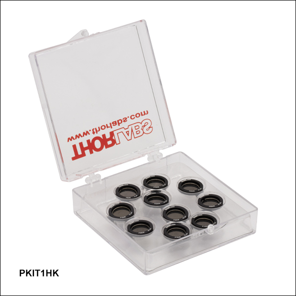
Zoom- Ten Precision Pinholes in Each Kit Covering Three Diameter Ranges:
- PKIT1HK: Ø5 µm - Ø100 µm
- PKIT2HK: Ø30 µm - Ø500 µm
- PKIT3HK: Ø150 µm - Ø1 mm
- Stainless Steel Foils are Blackened on Both Sides for Increased Absorbance
- Ø1/2" Black-Anodized Aluminum Housings Engraved with Item #
- Packaged in Protective Plastic Case for Easy Storage
The stainless steel precision pinholes in Ø1/2" housings described above are available kits of ten. Each kit is shipped in a plastic storage case that protects the pinholes from damage.
| Kit Item # | Pinhole Diameter (Item #) of Included Parts | |||||||||
|---|---|---|---|---|---|---|---|---|---|---|
| PKIT1HK | Ø5 µm (P5HK) |
Ø10 µm (P10HK) |
Ø15 µm (P15HK) |
Ø20 µm (P20HK) |
Ø25 µm (P25HK) |
Ø30 µm (P30HK) |
Ø40 µm (P40HK) |
Ø50 µm (P50HK) |
Ø75 µm (P75HK) |
Ø100 µm (P100HK) |
| PKIT2HK | Ø30 µm (P30HK) |
Ø40 µm (P40HK) |
Ø50 µm (P50HK) |
Ø75 µm (P75HK) |
Ø100 µm (P100HK) |
Ø150 µm (P150HK) |
Ø200 µm (P200HK) |
Ø300 µm (P300HK) |
Ø400 µm (P400HK) |
Ø500 µm (P500HK) |
| PKIT3HK | Ø150 µm (P150HK) |
Ø200 µm (P200HK) |
Ø300 µm (P300HK) |
Ø400 µm (P400HK) |
Ø500 µm (P500HK) |
Ø600 µm (P600HK) |
Ø700 µm (P700HK) |
Ø800 µm (P800HK) |
Ø900 µm (P900HK) |
Ø1 mm (P1000HK) |

 Zoom
Zoom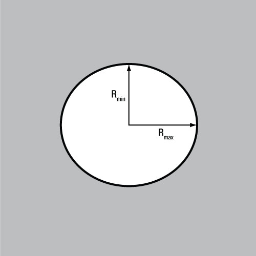
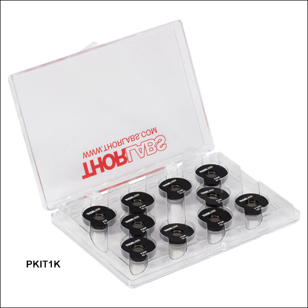
- Ten Precision Pinholes in Each Kit Covering Four Diameter Ranges:
- PKIT1K: Ø5 µm - Ø100 µm
- PKIT2K: Ø30 µm - Ø500 µm
- PKIT3K: Ø150 µm - Ø1 mm
- PKIT4K: Ø2 mm - Ø9 mm
- Stainless Steel Foils are Blackened on Both Sides for Increased Absorbance
- Ø1" Black-Anodized Aluminum Housings Engraved with Item #
- Packaged in Protective Plastic Case for Easy Storage
The stainless steel precision pinholes in Ø1" housings described above are available kits of ten. Each kit is shipped in a plastic storage case that protects the pinholes from damage.
| Kit Item # | Pinhole Diameter (Item #) of Included Parts | |||||||||
|---|---|---|---|---|---|---|---|---|---|---|
| PKIT1K | Ø5 µm (P5K) |
Ø10 µm (P10K) |
Ø15 µm (P15K) |
Ø20 µm (P20K) |
Ø25 µm (P25K) |
Ø30 µm (P30K) |
Ø40 µm (P40K) |
Ø50 µm (P50K) |
Ø75 µm (P75K) |
Ø100 µm (P100K) |
| PKIT2K | Ø30 µm (P30K) |
Ø40 µm (P40K) |
Ø50 µm (P50K) |
Ø75 µm (P75K) |
Ø100 µm (P100K) |
Ø150 µm (P150K) |
Ø200 µm (P200K) |
Ø300 µm (P300K) |
Ø400 µm (P400K) |
Ø500 µm (P500K) |
| PKIT3K | Ø150 µm (P150K) |
Ø200 µm (P200K) |
Ø300 µm (P300K) |
Ø400 µm (P400K) |
Ø500 µm (P500K) |
Ø600 µm (P600K) |
Ø700 µm (P700K) |
Ø800 µm (P800K) |
Ø900 µm (P900K) |
Ø1 mm (P1000K) |
| PKIT4K | Ø2 mm (P2000K) |
Ø2.5 mm (P2500K) |
Ø3 mm (P3000K) |
Ø3.5 mm (P3500K) |
Ø4 mm (P4000K) |
Ø4.5 mm (P4500K) |
Ø5 mm (P5000K) |
Ø7 mm (P7000K) |
Ø7.5 mm (P7500K) |
Ø9 mm (P9000K) |