 Products Home / Imaging Components / Mechanical Components for Microscopy / Motorized Pinhole Wheels
Motorized Pinhole Wheels
- 16 Pinholes from Ø25 μm to Ø2 mm
- Automated, Repeatable Positioning of Pinholes
- Encoded Motor Eliminates the Need for Realignment
- Uncoated and AR-Coated Options Available
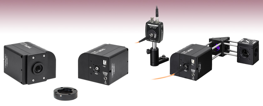
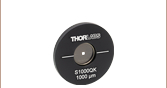
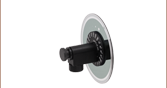
MPH16-A
Motorized Pinhole Wheel,
400 - 700 nm AR-Coated Optics
Dovetail Adapter Included
with Every Pinhole Wheel
for 30 mm Cage Compatibility
MPH16-A Motorized Pinhole Wheel in Confocal Imaging Setup (See the Applications Tab)
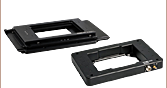
Front View
Back View
Application Idea


Please Wait
| Apertures Selection Guide |
|---|
| Single Precision Pinholes |
| Circular in Stainless Steel Foils |
| Circular in Stainless Steel Foils, Vacuum Compatible |
| Circular in Gold-Plated Copper Foils |
| Circular in Tungsten Foils |
| Circular in Molybdenum Foils |
| Square in Stainless Steel Foils |
| Pinhole Kits |
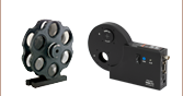
| Pinhole Wheels |
| Manual |
| Motorized |
| Pinhole Spatial Filter |
| Slits |
| Annular Apertures |
| Alignment Tools |
Click to Enlarge
Figure 2: Schematic of Internal Pinhole Wheel (See Specs Tab for Details)
Click to Enlarge
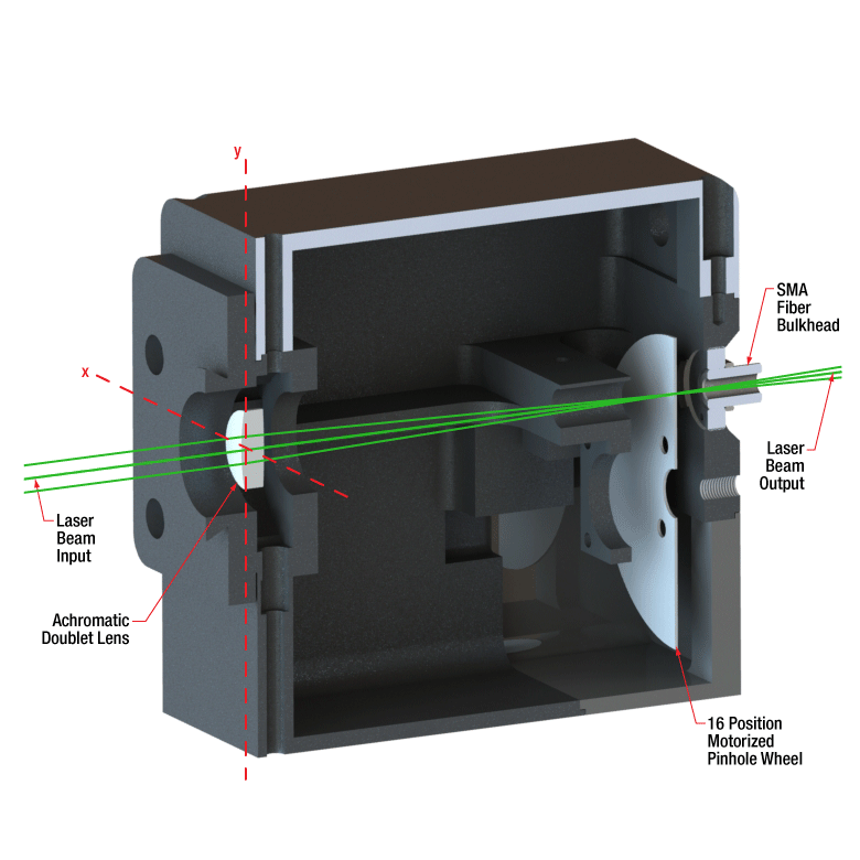
Figure 1: Cross-Section Schematic of a Motorized Pinhole Wheel
Features
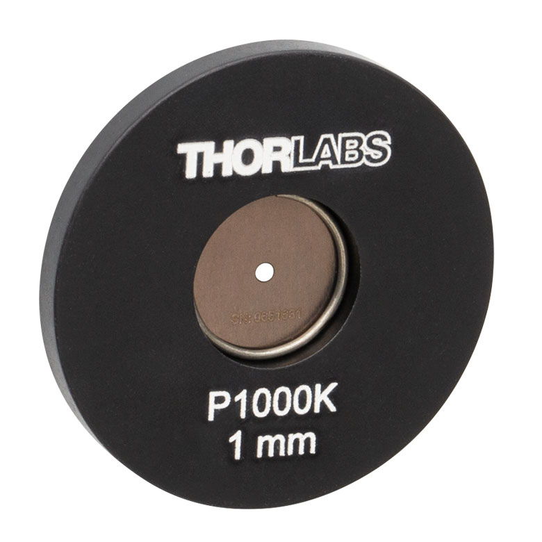
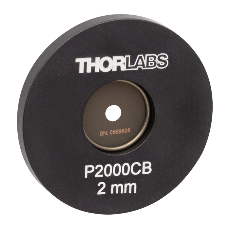
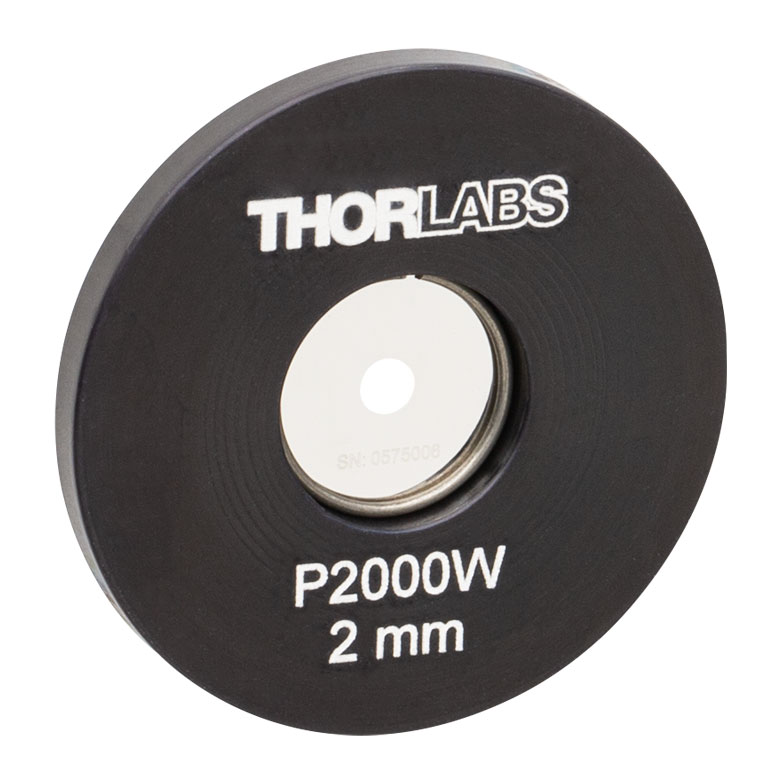
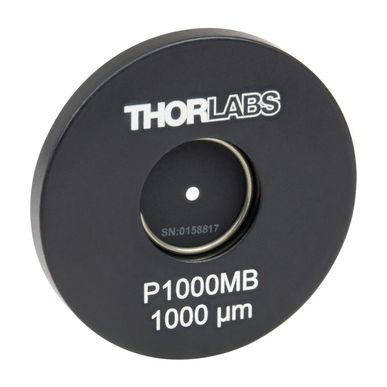
- 16 Pinhole Sizes: Ø25 µm to Ø2 mm (See Specs Tab for Details)
- Uncoated Optics or AR-Coated Optics for 400 - 700 nm or 650 - 1050 nm
- Quick and Repeatable Pinhole Positioning
- Free-Space Input Compatible with 30 mm Cage Systems (Using Included Dovetail Adapter)
- Fiber-Coupled Output with SMA Connector (Use Ø400 - Ø1000 µm Core MM Fiber)
- Compatible with 16 mm and 30 mm Cage Systems
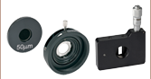
Thorlabs' Motorized Pinhole Wheels enable automated and repeatable positioning of pinholes for applications such as confocal laser scanning microscopy or scanning ophthalmoscopy. We offer a model with an uncoated doublet and pinhole wheel, as well as models with AR-coated optics for 400 - 700 nm or 650 - 1050 nm. Each pinhole wheel is a chrome-plated glass disk, manufactured using standard photolithography techniques, and features 16 etched pinholes ranging from Ø25 µm to Ø2 mm (see the Specs tab). The glass disk in each motorized AR-coated pinhole wheel is coated on both sides to increase transmission through the wheel for the specified wavelength range.
An optically encoded motor provides repeatable movement between pinholes with a resolution of 10 µm, without the need for realignment. The motorized pinhole wheel may be connected to a PC through a USB port and can be controlled using the provided GUI software or through DLL (see the Software tab to download the software package). As seen in Figure 1, light entering a motorized pinhole wheel is focused by an achromatic doublet lens through the pinhole wheel. Radial positioning of the pinhole is pre-aligned, but can be fine-tuned by the user through the GUI. The position of the focusing lens, labeled the y-axis in Figure 1, can be adjusted using the included 1.5 mm hex key. Light exiting the pinhole wheel can be coupled to an SMA multimode fiber or used as a free-space beam. A Ø400 - Ø1000 µm core SMA multimode fiber patch cable should be used to connect the pinhole wheel to a detector, because smaller core sizes cannot be aligned accurately.
These motorized pinhole wheels are used in Thorlabs' four-channel confocal microscopes and the confocal configurations of our Veneto® Inverted Microscope. The pinhole wheels can also be integrated into a custom confocal microscope system or other experimental setup (see the Applications tab). Each motorized pinhole wheel allows the user to simultaneously control the amount of in-focus light that reaches the detector and minimize signals from outside the focal plane. For thicker samples, the size of the pinhole is chosen based on the NA of the imaging objective. However, because a thick sample may generate significant signals from outside the focal plane, using a smaller pinhole can result in better optical sectioning and improve the signal-to-noise ratio of the resulting image. Conversely, for thinner samples that produce less light outside of the focal plane, choosing a larger pinhole size can help increase the amount of light that reaches the detector.

Click to Enlarge
Figure 5: Output Connected
to a 16 mm Cage System

Click to Enlarge
Figure 4: Output with SMA Fiber Connector Removed for Free Space Output
Click to Enlarge
Figure 3: Input Connected to
a 30 mm Cage System
Mounting Features
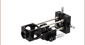
With cage system and dovetail compatibility, the input and output apertures of the motorized pinhole wheels are designed to allow for easy integration within custom experiments. The input aperture features a dovetail, which is designed to mate with our confocal laser scanning microscopy imaging systems. Using the included dovetail adapter, the user can connect the input to a 30 mm cage system. To do this, first insert the included 4-40 cap screws into the counterbored holes to attach the 30 mm cage assembly rods (sold separately), and then connect the adapter to the pinhole wheel input. Figure 3 shows the result. For additional mounting options, the base includes two mounting holes that accept both 8-32 and M4 threads.
The output aperture comes preinstalled with an SMA fiber connector for efficient light collection. When using the fiber connector, the fiber face is positioned 1 mm from the back side of the pinhole wheel. The SMA fiber adapter may be removed (see Figure 4) using an SPW801 spanner wrench to expose internal SM05 (0.535"-40) threading, which is compatible with our Ø1/2" Lens Tubes. Additionally, the output aperture is surrounded by four 4-40 tapped holes for compatibility with our 16 mm cage systems, as shown in Figure 5.
Other fiber connector adapters are available upon request; please contact Tech Support for details.
| Item # | MPH16-UC | MPH16-A | MPH16-B |
|---|---|---|---|
| Pinhole Wheel Specifications | |||
| Pinholes | 16 (Ø25 µm to Ø2 mm) | ||
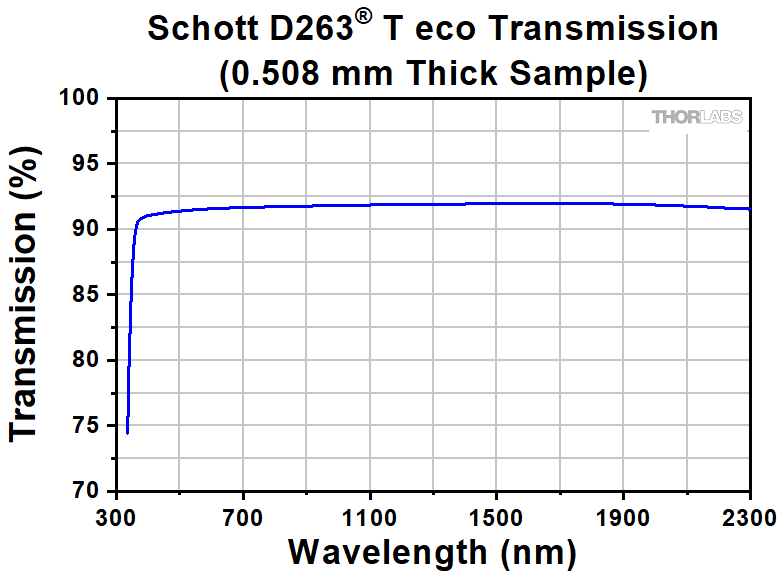
| Substrate (Click for Internal Transmission) |
Chrome-Plated Schott D263®a T eco (Data) | ||
| Substrate Thickness | 0.020" (0.508 mm) | ||
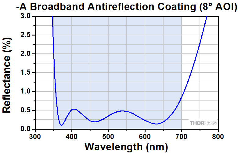
| AR Coatingb (Click for Graph) |
None | 350 - 700 nm, Ravg < 0.5% (Raw Data) |
650 - 1050 nm, Ravg < 0.5% (Raw Data) |
| Refractive Index | 1.5255 | ||
| Abbe Number (Ve) @ 546 nm | 55 | ||
| Positioning Accuracy | ±5.1 µm | ||
| Achromatic Doublet Specifications | |||
| Item # of Doublet | N/A | AC127-075-A | AC127-075-B |
| Focal Length | 75.0 mm | ||
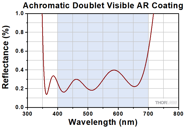
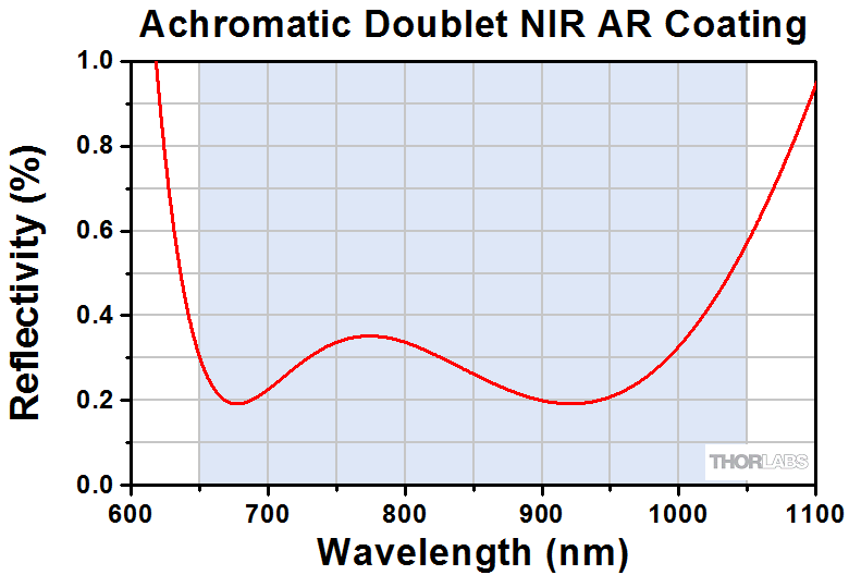
| AR Coatingc (Click for Graph) |
None | 400 - 700 nm, Ravg < 0.5% (Raw Data) |
650 - 1050 nm, Ravg < 0.5% (Raw Data) |
| Focal Length Shift & Transmission Graphs |
N/A | ||
| Size | Ø1/2" (Ø12.7 mm) | ||
| Clear Aperture | >Ø11.43 mm | ||
| Surface Quality | 40-20 Scratch-Dig | ||
| General Specifications | |||
| Input Aperture | Ø10 mm | ||
| Recommended Fiber | Multimode Fiber, Ø400 - Ø1000 µm Core, 0.22 NA | ||
| Operating Voltage | 24 VDC, 1.67 A | ||
| Input Power (Max)d | 200 mW/cm2 | ||
| Control | USB Cable, Software, and SDK Includede | ||
| Dimensions | 3.73" x 3.34" x 2.60" (94.8 mm x 84.7 mm x 66.0 mm) |
||
| Weight | 1.0 kg (2.2 lbs) | ||
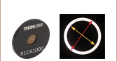
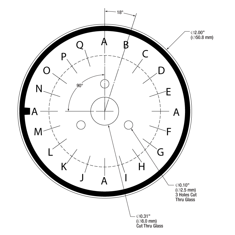
| Pinhole Wheel | |
|---|---|
| Positiona | Pinhole Size |
| A | Ø50 µm Annular Apertureb |
| B | Ø25 µm |
| C | Ø30 µm |
| D | Ø35 µm |
| E | Ø40 µm |
| F | Ø45 µm |
| G | Ø50 µm |
| H | Ø60 µm |
| I | Ø70 µm |
| J | Ø80 µm |
| K | Ø90 µm |
| L | Ø100 µm |
| M | Ø125 µm |
| N | Ø200 µm |
| O | Ø300 µm |
| P | Ø1000 µm |
| Q | Ø2000 µm |
Click to Enlarge
The pinhole wheel has 16 pinhole sizes; see the table to the left for the pinhole sizes. The MPH16-UC pinhole wheel is not AR coated, while the MPH16-A and MPH16-B pinhole wheels are AR coated for 350 - 700 nm and 650 - 1050 nm, respectively.
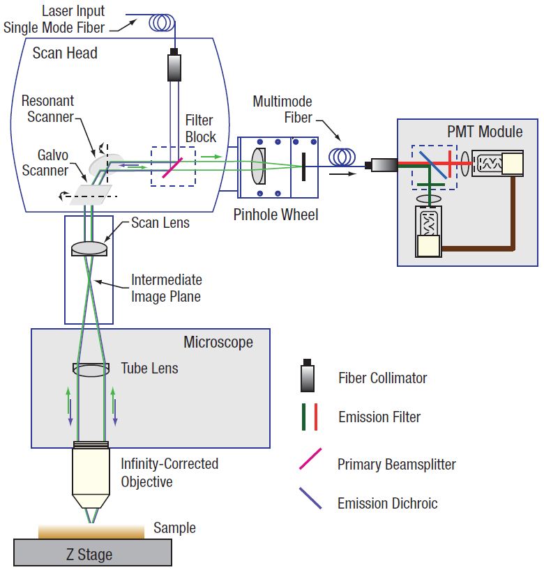
Confocal System Schematic
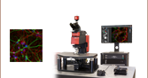
Motorized Pinhole Wheel in a Confocal Microscope
Our motorized pinhole wheels are designed for integration into confocal microscopy setups as shown in the diagram to the right. The pinhole wheel is located in the imaging path just before the photomultiplier tube (PMT) detector. Emitted light from the specimen is focused on the selected pinhole and then collected by a large-core multimode fiber for transmission to the PMT detector. A pinhole wheel, with multiple selectable pinholes, enables a user to select an appropriately sized pinhole for the intended applications.
The lithographically etched pinholes on the wheel prevent undesired signals outside the focal plane of the microscope from reaching the detector. Because only light from the focal plane of interest reaches the detectors, confocal microscopes are able to acquire high-resolution, optically-sectioned images from within a thick sample or to significantly reduce background fluorescence from thin culture samples.
While our motorized pinhole wheels are designed for Thorlabs' confocal microscopes, they can also be integrated into 16 mm and 30 mm cage systems. The image below illustrates part of a confocal microscope system using a KCB1C right-angle cube and BB1-E02 mirror to change the optical beam path. The DFM1 fluorescence filter cube takes the place of the filter block, but allows easy swapping of dichroic filter sets. Rather than a PMT detector, light that passes through the pinhole is collected by the PDA10A2 amplified photodetector.
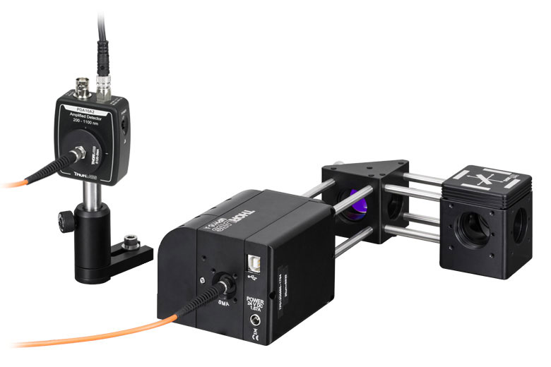
Click to Enlarge
MPH16-A Motorized Pinhole Wheel in Confocal Imaging Setup
Principles of Spatial Filters
An input Gaussian beam has spatially varying intensity "noise". When a beam is focused by a lens, the input beam is transformed into a central Gaussian spot (on the optical axis) and side fringes, which represent the unwanted "noise" (see Figure 1 below). The radial position of the side fringes is proportional to the spatial frequency of the "noise".
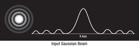
Figure 1
By centering a pinhole on a central Gaussian spot, the "clean" portion of the beam can pass while the "noise" fringes are blocked (see Figure 2 below).
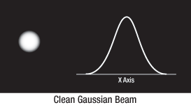
Figure 2
The diffraction-limited spot size at the 99% contour is given by:

where λ = wavelength, ƒ = focal length, D = diameter, and r = input beam radius at the 1/e2 point.
| Recommended Beam Parametersa | |
|---|---|
| Wavelength | Input Beam Radius (1/e2) |
| 405 nm | 1.5 mm |
| 488 nm | 1.8 mm |
| 532 nm | 1.9 mm |
| 632 nm | 2.3 mm |
Choosing the Correct Optics and Pinhole for Your Spatial Filter System
The correct optics and pinhole for your application depend on the input wavelength, source beam diameter, and desired exit beam diameter.
For example, suppose that you are using a 632 nm diode laser source that has an input beam radius (1/e2) of 2.3 mm with the MPH16 Motorized Pinhole Wheel. The equation for diffraction-limited spot size at the 99% contour is given above, and for this example, λ = (632 nm),
f = 75 mm for the achromatic doublet lens used in the MPH16, and r = 2.3 mm. Substitution yields:
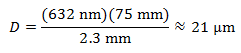
Diffraction-Limited Spot Size (632 nm Source, 2.3 mm Input Beam Radius)
The pinhole should be chosen so that it is approximately 30% larger than D. If the pinhole is too small, the beam will be clipped, but if it is too large, more than the TEM00 mode (the lowest-order transverse mode) will get through the pinhole. Therefore, for this example, the pinhole should ideally be 25 microns in diameter. For other wavelengths, see the table above for recommended beam diameters.
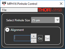
MPH16 Software GUI
Software
Version 4.0 (September 5, 2019)
The software package contains the installation files for the GUI interface, DLL files, SDK, and sample LabVIEW code. The software is compatible with Windows® 7 and 10 (64-bit) systems.
Software for the Motorized Pinhole Wheels
A link to the latest version of the Motorized Pinhole Wheel software is provided in the Software
box to the right. The software download page offers a link to the DLL, GUI interface, SDK, and sample LabVIEW™ code.
| Posted Comments: | |
义强 王
(posted 2023-07-19 09:44:08.25) 我想了解下这款针孔的调节事项 cdolbashian
(posted 2023-08-16 09:26:50.0) Thank you for reaching out to us here. A member of our local tech support team has reached out to you directly to address your inquiry! Max S
(posted 2021-07-26 15:12:28.91) The pinhole wheel does not seem like symmetrical. The reflectance is different if you compare both sides. Due to the quite limited mounting options on the side where the connectors are, I would like to use the pinhole wheel in flipped orientation. Does the pinhole wheel operates bidirectional just fine or might this cause some struggle due to the coating or so? YLohia
(posted 2021-07-30 02:54:44.0) Hello, the glass disk in each motorized AR-coated pinhole wheel is coated on both sides to increase transmission through the wheel for the specified wavelength range so it can be used bi-directionally. Craig Prater
(posted 2019-06-06 19:05:49.997) For use on an optical table, it would be far more convenient if this item had some 8-32 or 1/4-20 mounting holes (and their metric equivalents) on the bottom surface such that this unit could be mounted on pedestals or posts. I was really surprised to see that this unit had no options for mounting except dovetail or cage mount. It is really to heavy to support itself on cage mount rods. Because of the three covers, the bottom surface is also not flat so it will lead to an uncertain/unstable mounting if clamped on the top directly onto an optical table. YLohia
(posted 2019-06-07 09:25:37.0) Hello, thank you for your feedback. I have brought your suggestion up in our internal engineering forum for further consideration. shshin
(posted 2018-12-13 17:36:54.73) It seems that labview sdk for mph16 has no function to change the size of pinhole. Is there another sdk for this? nbayconich
(posted 2018-12-20 04:55:20.0) Thank you for contacting Thorlabs. When you open the Labview example ‘PinholePositionTest.vi’ you will get the test panel which shows a slider and position display for the Pinhole position. When first opening the slider will show a range from 0 to 100. Once you Run/Execute the example the slider will change from 0 to 15. The 0 to 15 are the Pinhole Positions as there are 16 pinholes in the MPH16. The sizes range from 25um to 2mm. For reference you can start the Standalone app Which comes with the SDK and check the UI for the specific sizes.
Neither the Labview Example nor Standalone app will connect to the device if the Com port setting (in device manager) does not match the Pinhole settings file. shshin
(posted 2018-06-19 02:01:02.503) About the 'Dovetail Adapter' included in 'MPH16'
I purchased your product, MPH16. I used 'Dovetail Adapter' to adapt 30mm cage system to Input port. But, there's no screw hole on it. It has hole but slightly biggher than 4/40(about 2.8mm). Also, It is not a hole for screw but just literally a 'hole'. How to adapt this thing to '30mm cage system'? YLohia
(posted 2018-06-19 12:04:44.0) Hello, you will have to use the 4-40 cap screws (included) to adapt to the back of the dovetail adapter. I will reach out to you directly with a screenshot. cbrideau
(posted 2016-01-11 20:49:43.46) Just got this, but need the manual so I know what commands to send it to move to a given pinhole size. Was very surprised to find that I couldn't just download the manual from the website like every other product. jlow
(posted 2016-01-12 08:51:56.0) Response from Jeremy at Thorlabs: We are currently revising the manual for this. We will be uploading the revised manual to the website within the next 2 weeks. 80kmh
(posted 2014-08-20 17:44:52.833) I want to use Labview to drive MPH.
I can not find labview file in the suppoort CD.
Tried several times, there is always error message or not working.
Could you please provide sample code or example code for labview?
I need your help I should. jlow
(posted 2014-08-20 02:37:03.0) Response from Jeremy at Thorlabs: We have a SDK for C++ that can possibly be adapted to LabVIEW. We will contact you directly about this. bryan.donaphon
(posted 2014-06-16 22:38:01.713) How susceptible is the MPH16 to magnets? I have a confocal microscope setup, and I was thinking of using magnets to secure glass coverslips to the objective stage. However, I want to make sure that these magnets will not interfere with the MPH16 in any way. besembeson
(posted 2014-06-26 11:26:50.0) Response from Bweh at Thorlabs: The MPH16 is optically encoded. Magnets on the coverslips are fairly far away from it. The magnetic field will have no effect on the MPH16 performance. arran.curran
(posted 2014-02-26 07:45:14.77) The indexing of the pinhole position (0-15) doesn't seem to correspond to pinhole size order (25 um, 30 um, ...). Can you list the indexing in order of pinhole size for those of us developing our own control software. This information doesn't seem to be included in the SDK. jlow
(posted 2014-02-27 05:01:14.0) Response from Jeremy at Thorlabs: We will contact you directly to provide this information. crowdifat
(posted 2013-11-20 09:35:09.12) I checked working status this item with software but there is some problem about position of pinhole.
Position of pinhole is not located center but upper position. All um size are same wrong position. Please let me know. jlow
(posted 2013-11-20 08:20:08.0) Response from Jeremy at Thorlabs: We will contact you directly to troubleshoot this. moonsik
(posted 2013-11-06 14:42:35.387) I want to use this product using Labview.
Could you give me a labview file or example file? tcohen
(posted 2013-11-07 03:42:18.0) Response from Tim at Thorlabs: Thank you for contacting us. We’ve emailed you to supply further documentation. icsong
(posted 2013-07-09 16:45:25.413) When the software with Labview will be available?
I tried to open the dll in Labview but some function is not working. please show me any information working with labview jlow
(posted 2013-07-19 08:48:00.0) Response from Jeremy at Thorlabs: We will get in contact with you directly about using the software in LabVIEW and a sample code. james.parker
(posted 2013-02-08 07:24:52.417) Is the focussing onto the pinhole (distance between lens and pinhole) adjustable? The text only describes radial positioning of the lens. Thank you. cdaly
(posted 2013-02-20 14:53:00.0) Response from Chris at Thorlabs: Thank you for your inquiry. The lens remains fixed but the set screw described in the text translates the internal pinhole assembly itself between the lens and fiber tip, along the optical axis. tcohen
(posted 2012-07-10 11:18:00.0) Response from Tim at Thorlabs: The lens used is our AC127-075-A (f=75mm). This product has had a recent modification and will have the ability to convert the SMA output to an SM05 output. There is also 16mm cage compatible mounting features which can be adapted to the 30mm cage with the SP05 cage adapter. We would like to discuss this product with you and we will contact you directly to continue this conversation. martin.vogel
(posted 2012-07-09 17:28:49.0) Hello, cool product indeed! May I ask two questions? 1) What is the effective focal length of the focusing lens in the MPH16? 2) Would it be possible to get the MPH16 with a free space *exit* port (no fiber connector) that is compatible to the 30mm cage system? Many thanks in advance! tcohen
(posted 2012-02-27 14:09:00.0) Response from Tim at Thorlabs: Here are some updates to your questions.
1. The pinhole wheel is a thin glass substrate coated with pinholes patterns. There is also a BB AR coating to reduce the reflection in 350 ~ 700 nm. The multimode fiber is place on the other side of the glass wheel. The fiber is place as close as possible to the wheel but usually leaving a 1 mm space. So the distance from the pinhole to the fiber end includes 0.5 mm in the glass and 1 mm in the air. The refractive index of the glass substrate is Ne=1.5255, Abbe number Ve=55.
2. Currently the SMA connector is the only mounting fixture for light collection. Special mounting holes are possible upon request.
3. There are DLLs to drive the pinhole wheel through a USB serial port. Software API with Labview demo will be available soon.
4. Azimuthal positioning is accomplished by an optically encoded motor which provides a resolution of 10 um along the circle.
5. Radial positioning is accomplished by adjusting the focusing lens with a set screw. tcohen
(posted 2012-02-24 10:10:00.0) Response from Tim at Thorlabs: Thank you for your feedback. Our design team has seen your questions and we will post an update with information soon. If you have any further questions in the meantime, we can assist you directly at techsupport@thorlabs.com. user
(posted 2012-02-24 09:26:00.0) Cool product, would like to use for non microscopy application. Here again, i also need to know how repeatable? And where is the pinhole located with respect to the external surfaces. user
(posted 2012-02-22 23:35:29.0) What is the distance the fiber would be from the pinhole or is there an imaging setup that launches the light from the pinhole into a fiber? Can this be ordered without the SMA connector so that the light passing through the pinhole can be used with a free space spectrometer? How does the software control which pinhole is being used is there a manual override or controller box option? Are there Labview drivers? Can the positioning of the pinhole be as accurate as what is accomplished with say the ST1XY-D? All that being said I really like this product as a concept and I hope it meets what we are looking for. |
| Apertures Selection Guide | |||
|---|---|---|---|
| Aperture Type | Representative Image (Click to Enlarge) |
Description | Aperture Sizes Available from Stocka |
| Single Precision Pinholesa |
 |
Circular Pinholes in Stainless Steel Foils | Ø1 µm to Ø9 mm |
 |
Circular Pinholes in Stainless Steel Foils, Vacuum Compatible |
Ø5 µm to Ø2 mm | |
 |
Circular Pinholes in Gold-Plated Copper Foils | Ø5 µm to Ø2 mm | |
 |
Circular Pinholes in Tungsten Foils | Ø5 µm to Ø2 mm | |
 |
Circular Pinholes in Molybdenum Foils | Ø5 µm to Ø2 mm | |
 |
Square Pinholes in Stainless Steel Foils | 100 to 1000 µm Square | |
| Slitsa |  |
Slits in Stainless Steel Foils | 3 mm Slit Lengths: 5 to 200 µm Widths 10 mm Slit Lengths: 20 to 200 µm Widths |
 |
Double Slits in Stainless Steel Foils | 3 mm Slit Lengths with 40, 50, or 100 µm Widths, Spacing of 3X or 6X the Slit Width |
|
| Annular Apertures | 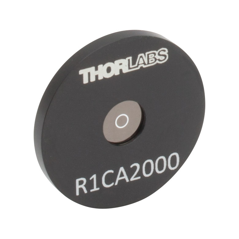 |
Annular Aperture Obstruction Targets on Quartz Substrates with Chrome Masks |
Ø1 mm Apertures with ε Ratiosb from 0.05 to 0.85 Ø2 mm Aperture with ε Ratiob of 0.85 |
| Pinhole Wheels |  |
Manual, Mounted, Chrome-Plated Fused Silica Disks with Lithographically Etched Pinholes |
Each Disk has 16 Pinholes from Ø25 µm to Ø2 mm and Four Annular Apertures (Ø100 µm Hole, 50 µm Obstruction) |
 |
Motorized Pinhole Wheels with Chrome-Plated Glass Disks with Lithographically Etched Pinholes |
Each Disk has 16 Pinholes from Ø25 µm to Ø2 mm and Four Annular Apertures (Ø100 µm Hole, 50 µm Obstruction) |
|
| Pinhole Kits | 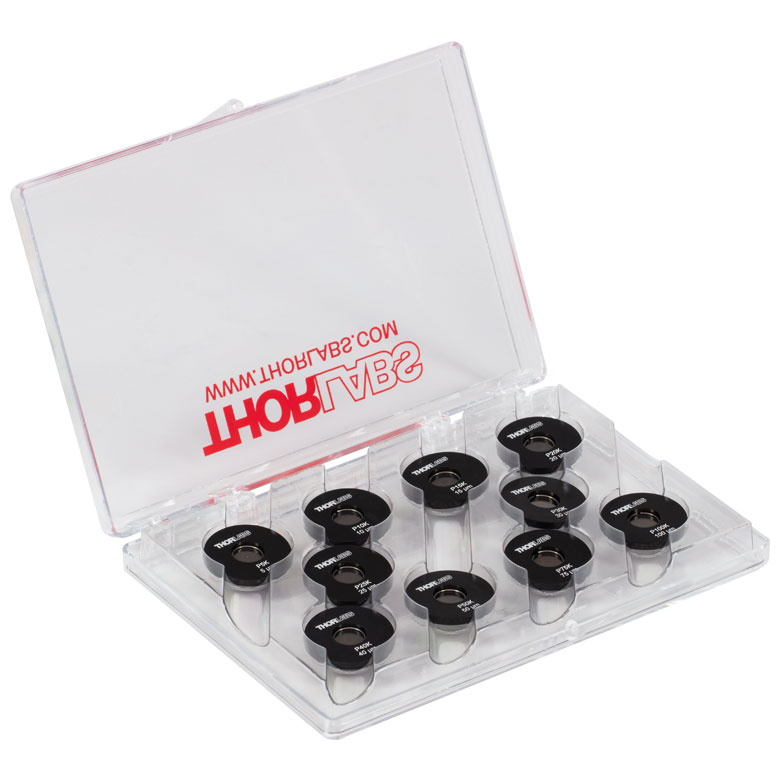 |
Stainless Steel Precision Pinhole Kits | Kits of Ten Circular Pinholes in Stainless Steel Foils Covering Ø5 µm to Ø9 mm |