 Products Home
Galvo-Galvo Scan Head and Controller
- Large-Area XY Scanning With User-Defined Scan Shapes
- ±7.5° Mechanical Scan Range (±15° Optical Scan Range)
- Pre-Aligned, Wired, and Calibrated for Plug-And-Play Use
- SM-Thread and Cage System Compatible
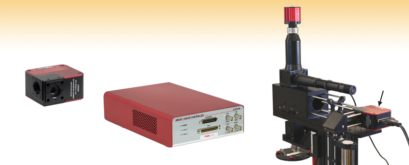
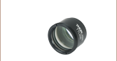
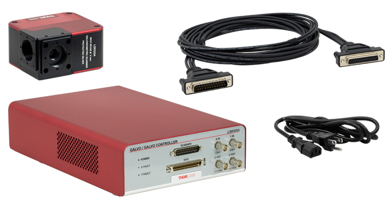
LSKGG4
4 mm Galvo-Galvo Scanner
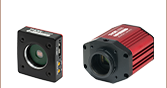
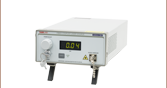
Controller
Scan Head
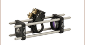
Application Idea
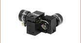
Galvo-Galvo Scanner Incorporated into a Cerna® DIY Microscope System
Galvo-Galvo Scanner


Please Wait
Click for Details
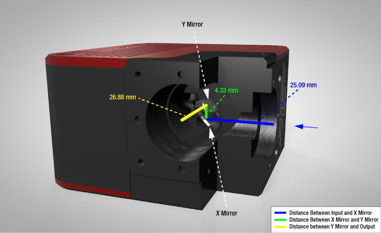
Figure 1.1 Cutaway View of Galvo-Galvo Scan Head
The scan lens being used with the scan head needs to be positioned such that its focus is at the midpoint between the X and Y Mirrors. The distance between the mirrors is indicated by the green line. For the input, that distance corresponds to 27.255 mm, while for the output, that corresponds to 29.045 mm. The input port has internal SM05 threads, internal SM1 threads, and four Ø6 mm bores for a 30 mm cage system, while the output port has internal SM1 threads and four
4-40 taps for a 30 mm cage system.
Features
- Optical Scan Range of ±15° (±7.5° Mechanical Scan Range) for Beams Up to Ø4 mm
- Driven by User-Supplied DC, Sine, Sawtooth, or Triangle Wave Signal
- BNC Connectors for Position Control and Readout
- Compatible with National Instruments Cards and Breakout Boxes
- Protected Silver Coating for High Reflectance in Visible and NIR
- Compact Scan Head Housing is SM-Threaded, 30 mm Cage System Compatible, and Post Mountable
Our LSKGG4(/M) Galvo-Galvo Scanner utilizes two galvo scan mirrors that deflect an incident laser beam in X and Y. Identical to the galvo-galvo scanner used in our Bergamo® III multiphoton microscopes and complete Cerna®-based confocal systems, each mirror has a mechanical scan range of ±7.5°, corresponding to an optical scan range of ±15°. This range is large enough to explore the entire diffraction-limited FN20 field of view of Thorlabs' SL50 scan lenses for laser scanning microscopy.
A National Instruments (NI) 68-pin connector is available to directly control and monitor the scanner via an NI card or breakout box (not included). The beam can also be steered by supplying DC, sine, sawtooth, or triangle wave drive signals through two BNC connectors. Two additional BNC connectors provide X and Y position feedback signals. This scanner is also compatible with Vidrio's ScanImage software.
Each scan mirror has a protected silver coating that provides high reflectance in the visible and NIR; see the Specs tab for details. Since the coating is metallic, its performance varies minimally over the ±7.5° mechanical scan range of the mirror.
The scan head is connected to the controller using the included DB25 cable. If using the BNC input connectors to drive the galvo mirrors, a drive voltage of ±10 V at an impedance of 10 kΩ will be required for each axis. The BNC output connectors have a voltage range of ±3.75 V and an impedance of 1 kΩ.
Click for Details
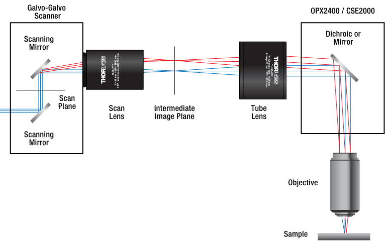
Figure 1.2 The LSKGG4 galvo-galvo scanner can be incorporated into a DIY laser scanning microscopy setup.
Mounting
The input face of the scan head has internal SM05 (0.535"-40) threads, internal SM1 (1.035"-40) threads, and four Ø6 mm bores spaced for our 30 mm cage system. The output face has internal SM1 threads and four 4-40 taps for our 30 mm cage system.
Please note that the scan lens needs to be positioned such that its entrance pupil is at the midpoint between the galvo mirrors; when being used at the input, the distance is 27.255 mm, while at the output, the distance is 29.045 mm. For the CLS-SL Scan Lens, an LCP02(/M) Cage System Size Adapter can be used to convert the 30 mm cage system to a 60 mm cage system to mount and position this scan lens at the correct distance using a LCP8S Cage Plate. An SM1A70 adapter with external SM1 and internal SM30 mounting threads will position our SL50-CLS2, SL50-2P2, or SL50-3P Scan Lens at the correct distance from the scanner output port.
The scan head has a mass of 0.56 kg, so it may be useful to support it directly using a Ø1/2" post or Ø1" post. Four 1/4"-20 tapped holes (M6) are located on the bottom.
| Table 2.1 LSKGG4(/M) Specifications | ||
|---|---|---|
| Internal Galvanometers | ||
| Item #s | QG4X-AG and QG4Y-AG | |
| Mirrors | ||
| Mechanical Scan Range | ±7.5° | |
| Optical Scan Range | ±15.0° | |
| Optical Scan Angle vs. Frequencya | (Click for Graph) Raw Data |
|
| Beam Diameter | 4 mm (Max) | |
| Coating | Protected Silver | |
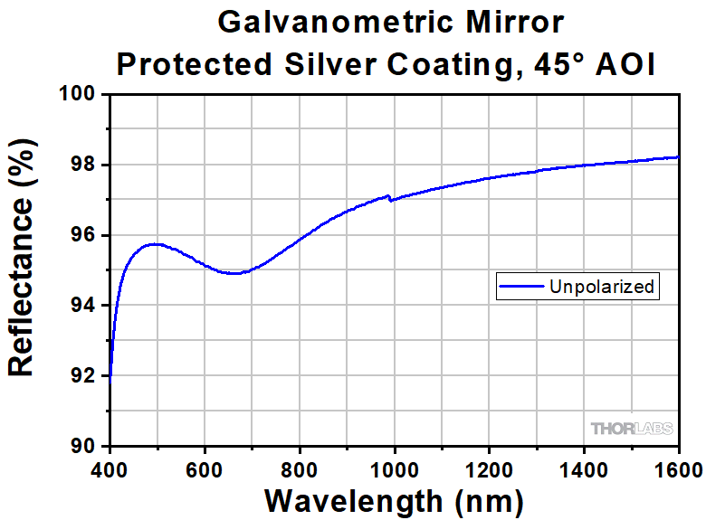
| Reflectance (Average)b | >92% (450 - 500 nm) >94.5% (500 - 2000 nm) >98% (2 - 10.6 µm) |
|
| X Mirror Clear Aperturec | Ellipse 6.22 mm Major Axis 4.00 mm Minor Axis |
|
| Y Mirror Clear Aperturec | Ellipse 5.82 mm Major Axis 5.22 mm Minor Axis |
|
| Front Surface Flatness |
<λ/4 (at 633 nm) | |
| Front Surface Quality | 40-20 Scratch-Dig | |
| Substrate | Fused Silica | |
| Position Sensor | ||
| Repeatability | 20 µradd | |
| Small Angle Step Responsee | 200 μs (Typical) | |
| Maximum Step Anglef | 0.65° | |
| Time Delay Between Input and Output Signal |
110 μs | |
| Linearity | 99.9% | |
| Scale Drift | 30 ppm/°C (Max) | |
| Zero Drift | 20 μrad/°C (Max) | |
| RMS Current (Max) |
2.0 A | |
| Peak Current | 6.0 A | |
| Input / Output | ||
| BNC Input | Voltage | -10 V to 10 V |
| Impedance | 10 kΩ | |
| Scale Factor | 1.33 V per Mechanical Degree | |
| BNC Output | Voltage | 0.5 V/deg. or ±3.75 V |
| Impedance | 1 kΩ | |
| Scale Factor | 0.5 V per Mechanical Degree | |
| Controller Voltage Input | 90 - 264 VAC, 50 - 60 Hz | |
| Power Consumption | 120 VA (Max) | |
| Physical | ||
| Scan Head Dimensions | 100.2 mm x 84.5 mm x 50.8 mm (3.95" x 3.33" x 2.00") |
|
| Controller Dimensions | 316.7 mm x 199.8 mm x 79.2 mm (12.47" x 7.87" x 3.12") |
|
| SM Threading | Internal SM05 (0.535"-40) Internal SM1 (1.035"-40) |
|
| Cage Compatibility | 30 mm Cage (4-40 Tap, 4 Places; Ø6 mm Bore, 4 Places) |
|
| Post Mounting | 1/4"-20 (M6) Tap, 4 Places | |
| Operating Temperature Range | 0 to 40 °C | |
Click to Enlarge
Figure 2.2 Typical Reflectance of One Galvo Mirror at 45° AOI
Please note that lot-to-lot variations will occur in the reflectance. Table 2.1 contains minimum average reflectance values over the recommended wavelength range.
Click for Details
Figure 2.3 Cutaway View of Galvo-Resonant Scan Head
The scan lens being used with the scan head needs to be positioned such that its focus is at the midpoint between the X and Y Mirrors. The distance between the mirrors is indicated by the green line. For the input, that distance corresponds to 27.255 mm, while for the output, that corresponds to 29.045 mm. The input port has internal SM05 threads, internal SM1 threads, and four Ø6 mm bores for a 30 mm cage system, while the output port has internal SM1 threads and four 4-40 taps for a 30 mm cage system.
Click to Enlarge
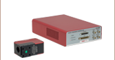
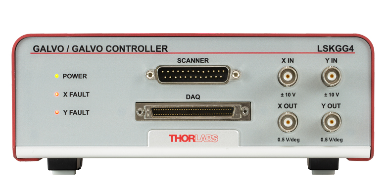
Figure 3.1 The front of the controller has a DB-25 connector for the scan head, as well as BNC connectors and an NI 68-pin connector for position control and readout.
Click to Enlarge
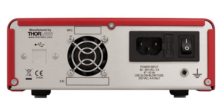
Figure 3.2 The back of the controller has a USB port to control the resonant scanner of the scan head, as well as a fuse holder, power switch, and grounding pin connector.
X IN and Y IN
BNC Female
| X IN and Y IN | |
|---|---|
| Input Signal Types | DC, Sine, Sawtooth, or Triangle Wave |
| Input Voltage Range | ±10 V |
| Input Impedance | 10 kΩ |
| Input Scale Factor |
1.33 V per Mechanical Degree |
X OUT and Y OUT
BNC Female
| X OUT and Y OUT | |
|---|---|
| Output Voltage Range | ±3.75 V |
| Output Impedance | 1 kΩ |
| Output Scale Factor | 0.5 V per Mechanical Degree |
DAQ
NI 68-Pin Connector*

* The impedances listed in Table 3.3 are provided for cases where the connector is used a non-NI DAQ card or function generator. They do not need to be taken into account if an NI cable is used to connect directly to an NI card.
| Table 3.3 DAQ | ||
|---|---|---|
| Pin | Name | Description |
| 21 | Y Position In | ±10 V Input 10 kΩ Impedance |
| 22 | X Position In | ±10 V Input 10 kΩ Impedance |
| 26 | X Velocity | Output Voltage Proportional to Scanner Velocity 1 kΩ Impedance |
| 28 | Y Velocity | Output Voltage Proportional to Scanner Velocity 1 kΩ Impedance |
| 30 | X Position Out | ±3.75 V Output 1 kΩ Impedance |
| 38 | Y Fault | Output Pulled from 12 V to 0 V When Fault Detector Trips 1 kΩ Impedance |
| 46 | X Fault | Output Pulled from 12 V to 0 V When Fault Detector Trips 1 kΩ Impedance |
| 54 | Ground | Ground Return for User Inputs |
| 57 | X Current | Output Voltage Proportional to Motor Current 1 kΩ Impedance |
| 60 | Y Current | Output Voltage Proportional to Motor Current 1 kΩ Impedance |
| 65 | Y Position Out | ±3.75 V Output 1 kΩ Impedance |
LSKGG4(/M) Shipping List
Click to Enlarge
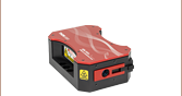
Figure 4.1 Item # Shown: LSKGG4
Each Galvo-Galvo Scanner Includes the Following:
- Scan Head
- Controller
- DB-25 Scan Head Control Cable
- Region-Specific Power Cord
Note because the galvo-galvo scanner can be steered using multiple methods of input signals, neither BNC cables nor an NI 68-pin cable are included.
| Posted Comments: | |
Shi Guo
(posted 2024-04-17 13:31:50.05) I need to build a confocal laser scanning setup and I need some technical assistance about Telecentric Scanning Lenses jpolaris
(posted 2024-04-22 07:14:05.0) Thank you for contacting Thorlabs. Telecentric scan lenses are designed to create a uniform spot size in the image plane at every scan position, which allows a high-quality image of the sample to be formed. There is some discussion about telecentric scan lenses at the following link. I have reached out to you directly to discuss in more detail your application requirements and goals. https://www.thorlabs.com/newgrouppage9.cfm?objectgroup_id=2910&tabname=Application_Info user
(posted 2023-10-09 16:34:41.62) Even when I turn on the power, power, X FAULT, and Y FAULT just flash and it doesn't work.
Please tell me the solution Raj M
(posted 2022-09-06 12:11:36.46) We are looking for a laser micromachining head/galvanometer scan head to attach it to a 5-axis CNC for a 3D part micromachining. Do you have any product that matches our description? cdolbashian
(posted 2022-09-16 09:43:26.0) Thank you for reaching out to us with this inquiry, and thinking of us for your application. I have reached out to you directly to discuss this request. user
(posted 2021-07-29 21:15:42.233) Dear Thorlabs staff,
I have LSKGG4 in lab, and wanted to control Galvo scan using Matlab. Could you please tell me how to do that? Do you have any Matlab code to be provided to us?
Thank you
Dayan Li YLohia
(posted 2021-07-29 01:58:07.0) Hello Dayan, thank you for contacting Thorlabs. The LSKGG4 does not have any direct software control capabilities. We do, however, provide an NI 68-pin connector on the controller that can be interfaced with a National Instruments Data Acquisition Card for programmatic control. Please contact National Instruments directly to find the best DAQ card for your needs. Georgi Yankov
(posted 2021-03-12 08:19:16.733) Hello,
Iskam yes nourished tozi laser skene for coy dalzhini on work. And can you work from dlzhin to vlnata 6.45 micronmeters YLohia
(posted 2021-03-12 03:38:27.0) Hello, thank you for contacting Thorlabs. Unfortunately, we don't have anyone at Thorlabs that speaks Bulgarian and Google Translate did not do a good job of translation-- would you be able to email your request in English? We will discuss this directly. Benjamin Judkewitz
(posted 2019-11-07 04:17:25.677) The idea is great, but the unfrotaunte choice of a small mirror diameter (4 mm) makes this useless for our (and many of our colleagues) applications. Are there any plans to offer 5 mm or 6 mm versions? This would be very interesting to us. Best, Benjamin YLohia
(posted 2019-11-07 11:01:45.0) Hello Benjamin, thank you for your feedback. We currently offer 5mm clear aperture Galvo-Resonant Scanners here : https://www.thorlabs.com/newgrouppage9.cfm?objectgroup_id=11579. I have posted your request on our internal product engineering forum for further consideration. user
(posted 2019-06-05 10:27:13.433) Hi there
Could you incorporate larger mirrors in this scan head, e.g. to accommodate a 8 mm beam waist? Thank you YLohia
(posted 2019-06-05 03:58:11.0) Hello, thank you for contacting Thorlabs. We will reach out to you directly to discuss the possibility of offering this customization. andriy.chmyrov
(posted 2019-01-25 16:19:29.63) Dear Tech Support,
could you, please, highlight the differences of LSKGG4/M compare to 'an ordinary' GVS002 XY-galvo set? One obvious thing is an easy integration into a cage system. What are the other key benefits which are included in 5 times higher price?
Thanks for your feedback! llamb
(posted 2019-01-29 08:46:50.0) Thank you for contacting Thorlabs. For a few key advantages, the LSKGG4/M offers a faster max full angle scan rate (500 Hz vs 250 Hz for a sine wave input), a faster small angle step response (130 µs vs 300 µs), better repeatability (within 8 µrad instead of 15 µrad), and overall a more user-friendly design ready for plug-and-play use. It has a National Instruments 68-pin connector for direct control from an NI card, and it is also compatible with Vidrio's ScanImage software. We will reach out to you directly to see if this product is best suited for your application. user
(posted 2018-06-21 03:51:28.26) Hello. I want to know whether the resonant mirror's scanning velocity is variable or not. YLohia
(posted 2018-06-26 10:11:44.0) The scan velocity is variable from 0-500 Hz. amelie2777
(posted 2017-10-30 09:13:46.637) Is the LSK-GG galvo mirror system operated at a closed-loop condition?
For a small angle (±0.2°), what is the (small angle) step response and what is the maximum scan frequency or (small angle) bandwidth?
What is the angular resolution? Thanks. nbayconich
(posted 2017-11-09 12:08:14.0) The LSK-GG allows customer access to all input and output signals to the galvos. It is completely up to the customer how they want to drive the mirrors. The kit is merely the galvos with controllers. Any interfacing with a DAQ card/system will have to be done by the customer. For closed-loop operation, the customer would have to write their own script. ThorImage, for example, drives these in Open Loop mode, that is, it doesn’t look at the encoder signal from the mirrors. It just feeds a sinusoidal wave to the mirrors so that they scan the field of view.
https://www.thorlabs.com/newgrouppage9.cfm?objectgroup_id=10647
On the Specs tab we have the Small Angle Step Response to be 130us (Typical). The response corresponds to a 0.1 deg movement from 1% to 99% of its final position.
The Specs tab also mentions a bandwidth of 500Hz for full swing (-10V to 10V or -7.5 deg to 7.5 deg mechanical). h.wu
(posted 2017-05-21 12:47:08.213) Dear Thorlabs, could you tell me the damage threshold for LSK-GG? Is the optical scan range of LSK-GG dependent upon the input beam size?
I also would like to know the diameter of the view field (field of view) for LSK-GG with SL50-CLS2 scan lens at the intermediate image plane.
I will use the NI 68-Pin connector of the controller for position control and readout so how could I put 200 kΩ resistors in pin 21 and 22 positions (between NI 68-Pin connector of the controller and NI SHC68-68-EPM cable)? Or 200 kΩ resistors were pre-installed inside the NI 68-Pin connector of the controller? The same question for 2 kΩ in pin 26, 28, 30, 57, 60 and 65.
Why is the price of LSK-GG so expensive compared to that of GVS002/M? Could you provide special offers or bundle deals for such complete system package (LSK-GG + SL50-CLS2 + TL200-CLS2)?
Thank you. nbayconich
(posted 2017-06-07 04:05:09.0) Thank you for contacting Thorlabs. At the moment we do not have a damage threshold specification for the LSK-GG but they are intended to be used with ti sapphire lasers up to 1 watt CW power that fills the clear aperture.
The SL50-CLS2 has a smaller optical scan angle we also have the CLS-SL if you need a larger field of view.
The field of view will be close to the size of the image at the focal plane, but if you want diffraction-limited performance, you must limit the input to be within the below field of view:
23.8 x 23.8 mm2
The scanner is meant for a Ø4mm beam or smaller but the scan range is not dependent on the input beam size.
SL50 scan lenses have a smaller FOV. We have the CLS-SL if you need a bigger FOV. The field of view will close to the size of the image at the focal plane, but if you need diffraction-limited performance, you should limit the input to be within the field of view: 23.8 x 23.8 mm2
The price of the LSK-GG compared to the GVS galvo units is significantly higher because the GVS series are more intended for OEM applications and also do not support a simple plug and play configuration like the LSK-GG.
A Techsupport representative will contact you directly with more information. |