 Products Home
Q-Switched Picosecond Microchip Laser Systems

- Sub-Nanosecond Pulse Duration
- Wavelengths Available: 515 nm, 1030 nm, and 1064 nm
- High Pulse Energy or High Repetition Rate Versions
- Turnkey Material Processing Capability
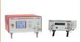
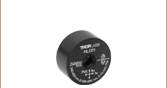
QSL103A
Picosecond Microchip Laser Head,
35 - 50 µJ Pulse Energy (Typ.),
8 - 10 kHz Rep. Rate,
Controller Included
The head of the QSL106B Laser (controller included) is mounted on the QSLB1 Base (sold separately below), increasing the laser beam height from 25.0 mm to 75.0 mm and providing additional thermal stability.


Please Wait
| Key Specificationsa | |||
|---|---|---|---|
| Item # | QSL52A | QSL103A | QSL106B |
| Center Wavelength | 515 ± 1 nm | 1030 ± 1 nm | 1064 ± 1 nm |
| Average Output Power (Typical)b,c | 175 - 225 mW | 350 - 450 mW | 150 - 250 mW |
| Repetition Rateb | 9 - 13 kHz | 8 - 10 kHz | 80 - 120 kHz |
| Pulse Energy (Typical)b,c | 16 - 20 µJ | 35 - 50 µJ | 1.7 - 2.2 µJ |
| Output Peak Power | >30 kW | >65 kW | >2.5 kW |
| Pulse Durationb | 500 ± 100 ps | 550 ± 100 ps | |
| Ellipticity | >0.65 | >0.94 | >0.92 |
Got Questions?
Our engineers and expertise are here for you!

Adam Knapp
Ultrafast Optoelectronics
General Manager
If you are not sure whether our catalog items meet your needs, we invite you to contact us. Or ask about a loan, so you can try them out for yourself, in your own lab. We can also support custom or OEM requirements you may have.
Just press the button, and we'll get back to you within the next business day.

Features
- 515 nm, 1030 nm, or 1064 nm Center Wavelength
- Sub-Nanosecond Pulse Duration
- Typical Pulse Energies Up to
50 µJ (See Table to the Right) - >65 kW Output Peak Power Available
- Compatible with 30 mm Cage System Components
- Integrated Control Electronics
- Trigger Output for Pulse Monitoring
Applications
- Material Processing
- Photoacoustic Imaging
- Fluorescence Lifetime Imaging
- Harmonic Generation
- LIDAR
- Laser-Induced Breakdown Spectroscopy
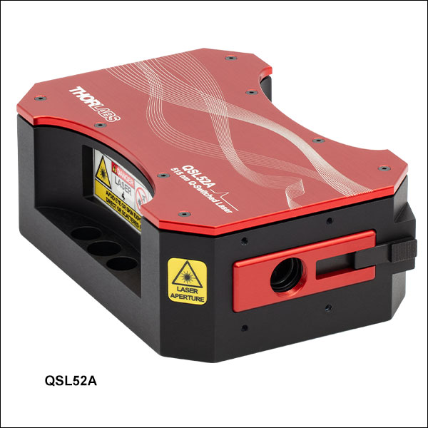
Thorlabs' Q-Switched Picosecond Microchip Lasers Systems are compact laser systems designed to provide a turnkey, alignment-free solution for picosecond pulses at 515 nm, 1030 nm, or 1064 nm. The compact microchip laser cavity design with a fiber-coupled pump laser produces a high-quality beam. Available with visible (Item # QSL52A), high pulse energy infrared (Item # QSL103A), or high repetition rate infrared (Item # QSL106B) output, these sources support a variety of applications, such as material processing or harmonic generation. For full performance specifications, please see the Specs tab. Each picosecond laser system includes a laser head and a controller that have integrated drive electronics, temperature stabilization, and safety interlocks. The laser head also includes a manual slide shutter which can be used to cover the laser aperture.
Laser Selection
In addition to material processing and harmonic generation, Thorlabs' Q-Switched Picosecond Microchip Lasers are also ideal for other applications, such as photoacoustic imaging, fluorescence lifetime imaging, LIDAR, and laser-induced breakdown spectroscopy, with each laser having unique characteristics suited to different applications. With higher energy 515 nm photons, the QSL52A laser can process material efficiently or serve as an excitation source for many fluorophores. Producing 35 - 50 µJ pulses with around 500 ps duration, the QSL103A laser has a high pulse energy and peak power, making it capable of high-volume material removal or efficient harmonic generation. For precision applications requiring a small mode-field diameter and high throughput, the QSL106B laser, with its higher 80 - 120 kHz typical repetition rate, is an appropriate selection. This higher repetition rate version may also be useful as a seed for high-power fiber amplification (please see our Ytterbium-Doped Fiber Amplifiers for turnkey amplifier options), allowing for more efficient and higher volume material removal processes. Note that the average output power, repetition rate, pulse duration, and pulse energy are fixed values that vary from device to device and cannot be adjusted by the user.
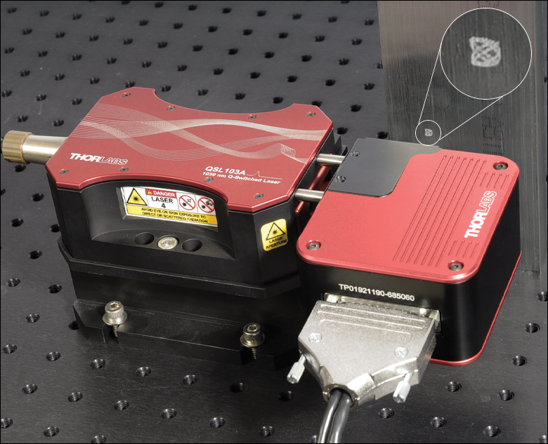
Click to Enlarge
An LSKGG4 Galvo-Galvo Scanner is mounted with ER1 1" long 30 mm Cage System Assembly Rods at the QSL103A Laser output to machine a pattern into aluminum. The inset shows the pattern created in the material.
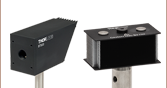
Optical Emission
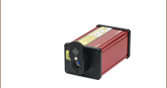
The output from these sources is uncollimated and weakly divergent, allowing for control over the beam diameter. The laser head features SM05 (0.535"-40) internal threading around the beam aperture, as well as 4-40 tapped holes for compatibility with our 30 mm cage components, as seen in the image to the left. To compensate for any beam misalignment at the laser output, a collimating lens can be mounted in a CP1XY cage plate with XY translation. The QSL52A laser output is elliptical, with an ellipticity of >0.65, as can be seen in the beam profile on the Specs tab, but a circular output beam can be generated using the setup and list of parts given where the laser is sold below.
For external beam attenuation, we recommend using Thorlabs' neutral density filters. A SHBH025 diaphragm shutter mounted in a SHCP025 adapter (for cage system compatibility) can also be added in front of the laser aperture to remotely block the laser output.
Mounting
The laser head housing includes six clearance holes for mounting, four for 8-32 (M4) cap screws and two for 1/4"-20 (M6) cap screws. When directly mounted to an optical table or breadboard, the output beam height is 0.98" (25.0 mm).
For applications that require an increased beam height, the QSLB1 Base (offered separately below) can be used to bring the output beam height to 2.95" (75.0 mm), as seen at the top right of this page, while also providing thermal stability. Alternatively, the laser head can be mounted on a raised breadboard.
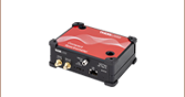
Electrical Connections
Each laser system is shipped with an umbilical cable for connecting the laser head and controller. This laser system integrates all required drive electronics, safety interlocks, and temperature stabilization needed for operation; a block diagram with more details can be found on the Specs tab. Note that the power supply is built into the unit and a region-specific power cord is included with each laser. Please see the Shipping List tab for a list of all items included with the laser.
Panel Features
A trigger out (SMA female) is included on the laser head, which can be used for monitoring the output pulse and repetition rate, as well as for timing the arrival of a pulse with an electronic trigger. An indicator LED is also included for the laser emission.
All required safety features are included with the controller, including a key switch, an interlock pin, and a momentary switch to enable the laser output; see the Front & Back Panels tab for more details on the panel features. Note that the controller front panel includes dual color (red/green) status LEDs for the TEC and laser emission status which are designed to be visible through most safety glasses.
| Item # | QSL52A | QSL103A | QSL106B |
|---|---|---|---|
| Center Wavelength | 515 ± 1 nm | 1030 ± 1 nm | 1064 ± 1 nm |
| Average Output Powera,b | 175 - 225 mW | 350 - 450 mW | 150 - 250 mW |
| Repetition Ratea | 9 - 13 kHz | 8 - 10 kHz | 80 - 120 kHz |
| Pulse Energy (Typical)a,b | 16 - 20 µJ | 35 - 50 µJ | 1.7 - 2.2 µJ |
| Output Peak Power | >30 kW | >65 kW | >2.5 kW |
| Pulse Durationa | 500 ± 100 ps | 550 ± 100 ps | |
| Typical Pulses |  |
 |
 |
| Output Spectrum (Typical) |  |
 |
 |
| Power Stability (RMS) | <1% over 8 hours | <0.5% over 8 hours | |
| Beam Diameter (1/e2), at 100 mm | 1 mm | 3 mm | |
| Beam Divergence (1/e2), Typical | 5 mrad | 10 mrad | |
| Beam Quality (M2) | <1.3 | <1.2 | <1.3 |
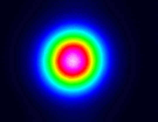
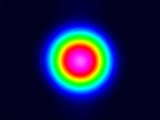
| Ellipticity | >0.65 | >0.94 | >0.92 |
| Beam Profile (Typical) | 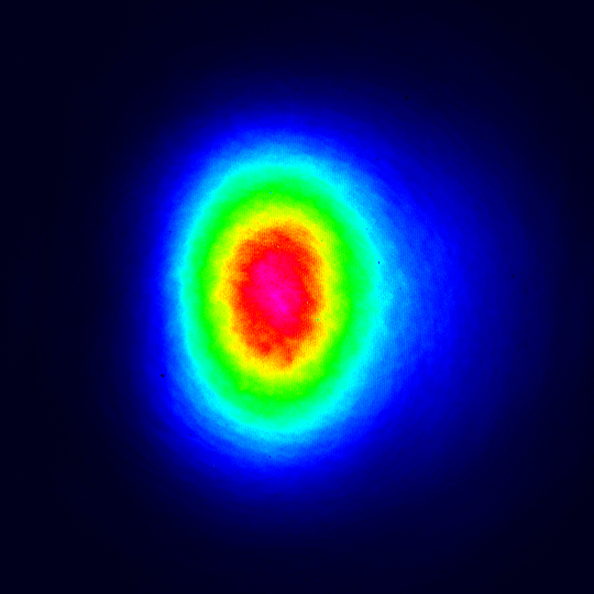 |
 |
 |
| Power, Environmental, and Physical Specifications | |
|---|---|
| AC Input Frequency Range to Power Supply | 50 - 60 Hz |
| AC Input Voltage to Power Supply | 100 V to 250 VAC |
| Power Consumption (Typical) | 22 W |
| Trigger Out | 1 VPP, 50 Ω |
| Relative Trigger Jitter | <10 ps |
| Optical Repetition Rate Jitter (RMS) | <5% of Repetition Rate |
| Operating Temperature Range | 10 to 45 °C |
| Storage Temperature Range | 0 to 60 °C |
| Laser Head Weight | 0.8 kg |
| Laser Controller Weight | 1.7 kg |
| Laser Head Dimensions | 136.3 mm x 88.9 mm x 47.1 mm (5.37" x 3.50" x 1.85") |
| Laser Controller Dimensions | 307.4 mm x 149.8 mm x 84.0 mm (12.10" x 5.90" x 3.31") |
| Lifetime | 10 000 hours |
Click to Enlarge
Block diagram depicting the internal architecture of the laser control system with drive electronics, safety interlocks, and temperature stabilization. The dual color TEC LED indicator (red/green) blinks during the 45 to 90 s warm up and glows continuously when temperature stability has been achieved.
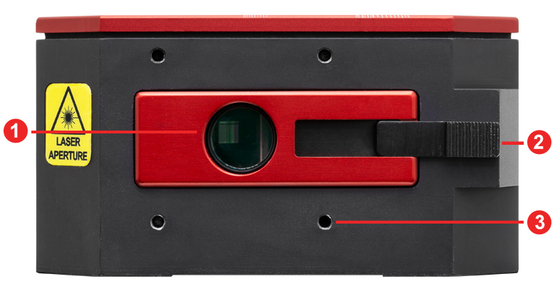
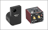
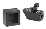
QSL Series Laser Head Front and Back Panels
| Front Panel | |
|---|---|
| Call Out | Description |
| 1 | Laser Aperture with SM05 (0.535”-40) Internal Threads |
| 2 | Manual Shutter |
| 3 | 4-40 Threads Spaced for 30 mm Cage Compatibility (4 Places) |
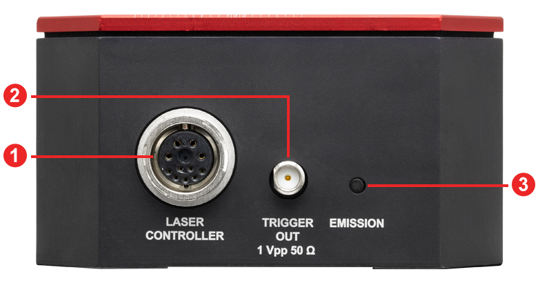
| Back Panel | |
|---|---|
| Call Out | Description |
| 1 | Receptacle for Umbilical Cable to Laser Controller |
| 2 | Trigger Out (Female SMA) |
| 3 | Laser Emission Indicator LED |
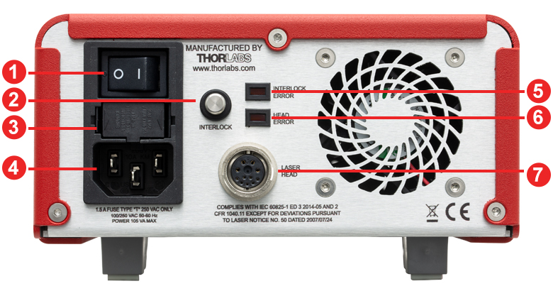
QSL Series Controller Front and Back Panels
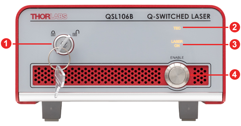
| Front Panel | |
|---|---|
| Call Out | Description |
| 1 | Interlock Key Switch |
| 2 | TEC Status LED |
| 3 | Laser Emission Status LED |
| 4 | Laser Enable Switch |
| Back Panel | |
|---|---|
| Call Out | Description |
| 1 | Main Power Switch |
| 2 | Interlock Connector |
| 3 | Fuse Holder |
| 4 | AC Power Cord Connector |
| 5 | Interlock Error Status LED |
| 6 | Head Error Status LED |
| 7 | Receptacle for Umbilical Cable for Laser Head |
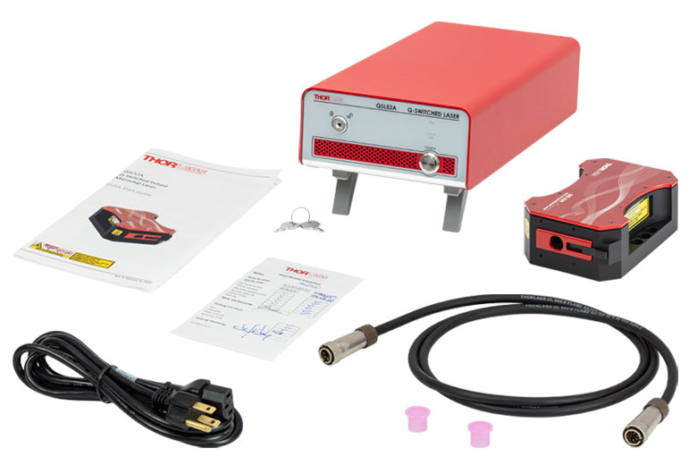
Click to Enlarge
QSL Series Q-Switched Picosecond Microchip Lasers
Each QSL Series Q-Switched Picosecond Microchip Laser is shipped with the following:
- Laser Head
- Laser Controller
- Power Cord According to Local Power Supply, 2.3 m (7.5')
- Laser Interlock Keys (2 Pcs)
- Interlock Pin (Installed)
- Umbilical Cable, 1.3 m (4.3')
- Printed Quick Start Guide
- Quality Control Form
Laser Safety and Classification
Safe practices and proper usage of safety equipment should be taken into consideration when operating lasers. The eye is susceptible to injury, even from very low levels of laser light. Thorlabs offers a range of laser safety accessories that can be used to reduce the risk of accidents or injuries. Laser emission in the visible and near infrared spectral ranges has the greatest potential for retinal injury, as the cornea and lens are transparent to those wavelengths, and the lens can focus the laser energy onto the retina.
 |
 |
 |
 |
 |
 |
 |
 |
 |
Safe Practices and Light Safety Accessories
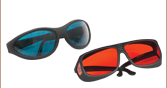
- Laser safety eyewear must be worn whenever working with Class 3 or 4 lasers.
- Regardless of laser class, Thorlabs recommends the use of laser safety eyewear whenever working with laser beams with non-negligible powers, since metallic tools such as screwdrivers can accidentally redirect a beam.
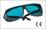
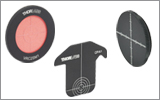
- Laser goggles designed for specific wavelengths should be clearly available near laser setups to protect the wearer from unintentional laser reflections.
- Goggles are marked with the wavelength range over which protection is afforded and the minimum optical density within that range.
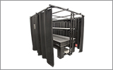
- Laser Safety Curtains and Laser Safety Fabric shield other parts of the lab from high energy lasers.
- Blackout Materials can prevent direct or reflected light from leaving the experimental setup area.
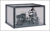
- Thorlabs' Enclosure Systems can be used to contain optical setups to isolate or minimize laser hazards.
- A fiber-pigtailed laser should always be turned off before connecting it to or disconnecting it from another fiber, especially when the laser is at power levels above 10 mW.
- All beams should be terminated at the edge of the table, and laboratory doors should be closed whenever a laser is in use.
- Do not place laser beams at eye level.
- Carry out experiments on an optical table such that all laser beams travel horizontally.
- Remove unnecessary reflective items such as reflective jewelry (e.g., rings, watches, etc.) while working near the beam path.
- Be aware that lenses and other optical devices may reflect a portion of the incident beam from the front or rear surface.
- Operate a laser at the minimum power necessary for any operation.
- If possible, reduce the output power of a laser during alignment procedures.
- Use beam shutters and filters to reduce the beam power.
- Post appropriate warning signs or labels near laser setups or rooms.
- Use a laser sign with a lightbox if operating Class 3R or 4 lasers (i.e., lasers requiring the use of a safety interlock).
- Do not use Laser Viewing Cards in place of a proper Beam Trap.
Laser Classification
Lasers are categorized into different classes according to their ability to cause eye and other damage. The International Electrotechnical Commission (IEC) is a global organization that prepares and publishes international standards for all electrical, electronic, and related technologies. The IEC document 60825-1 outlines the safety of laser products. A description of each class of laser is given below:
| Class | Description | Warning Label |
|---|---|---|
| 1 | This class of laser is safe under all conditions of normal use, including use with optical instruments for intrabeam viewing. Lasers in this class do not emit radiation at levels that may cause injury during normal operation, and therefore the maximum permissible exposure (MPE) cannot be exceeded. Class 1 lasers can also include enclosed, high-power lasers where exposure to the radiation is not possible without opening or shutting down the laser. |  |
| 1M | Class 1M lasers are safe except when used in conjunction with optical components such as telescopes and microscopes. Lasers belonging to this class emit large-diameter or divergent beams, and the MPE cannot normally be exceeded unless focusing or imaging optics are used to narrow the beam. However, if the beam is refocused, the hazard may be increased and the class may be changed accordingly. |  |
| 2 | Class 2 lasers, which are limited to 1 mW of visible continuous-wave radiation, are safe because the blink reflex will limit the exposure in the eye to 0.25 seconds. This category only applies to visible radiation (400 - 700 nm). |  |
| 2M | Because of the blink reflex, this class of laser is classified as safe as long as the beam is not viewed through optical instruments. This laser class also applies to larger-diameter or diverging laser beams. |  |
| 3R | Class 3R lasers produce visible and invisible light that is hazardous under direct and specular-reflection viewing conditions. Eye injuries may occur if you directly view the beam, especially when using optical instruments. Lasers in this class are considered safe as long as they are handled with restricted beam viewing. The MPE can be exceeded with this class of laser; however, this presents a low risk level to injury. Visible, continuous-wave lasers in this class are limited to 5 mW of output power. |  |
| 3B | Class 3B lasers are hazardous to the eye if exposed directly. Diffuse reflections are usually not harmful, but may be when using higher-power Class 3B lasers. Safe handling of devices in this class includes wearing protective eyewear where direct viewing of the laser beam may occur. Lasers of this class must be equipped with a key switch and a safety interlock; moreover, laser safety signs should be used, such that the laser cannot be used without the safety light turning on. Laser products with power output near the upper range of Class 3B may also cause skin burns. |  |
| 4 | This class of laser may cause damage to the skin, and also to the eye, even from the viewing of diffuse reflections. These hazards may also apply to indirect or non-specular reflections of the beam, even from apparently matte surfaces. Great care must be taken when handling these lasers. They also represent a fire risk, because they may ignite combustible material. Class 4 lasers must be equipped with a key switch and a safety interlock. |  |
| All class 2 lasers (and higher) must display, in addition to the corresponding sign above, this triangular warning sign. |  |
|
Pulsed Laser Emission: Power and Energy Calculations

Determining whether emission from a pulsed laser is compatible with a device or application can require referencing parameters that are not supplied by the laser's manufacturer. When this is the case, the necessary parameters can typically be calculated from the available information. Calculating peak pulse power, average power, pulse energy, and related parameters can be necessary to achieve desired outcomes including:
- Protecting biological samples from harm.
- Measuring the pulsed laser emission without damaging photodetectors and other sensors.
- Exciting fluorescence and non-linear effects in materials.
Pulsed laser radiation parameters are illustrated in Figure 170A and described in Table 170B. For quick reference, a list of equations is provided below. The document available for download provides this information, as well as an introduction to pulsed laser emission, an overview of relationships among the different parameters, and guidance for applying the calculations.
|
Equations: |
||||
 |
and |  |
||
 |
||||
 |
||||
 |
||||
Peak power and average power calculated from each other: |
||||
 |
and |  |
||
| Peak power calculated from average power and duty cycle*: | ||||
 |
*Duty cycle ( ) is the fraction of time during which there is laser pulse emission. ) is the fraction of time during which there is laser pulse emission. |
|||
Click to Enlarge
Figure 170A Parameters used to describe pulsed laser emission are indicated in this plot and described in Table 170B. Pulse energy (E) is the shaded area under the pulse curve. Pulse energy is, equivalently, the area of the diagonally hashed region.
| Table 170B Pulse Parameters | |||||
|---|---|---|---|---|---|
| Parameter | Symbol | Units | Description | ||
| Pulse Energy | E | Joules [J] | A measure of one pulse's total emission, which is the only light emitted by the laser over the entire period. The pulse energy equals the shaded area, which is equivalent to the area covered by diagonal hash marks. | ||
| Period | Δt | Seconds [s] | The amount of time between the start of one pulse and the start of the next. | ||
| Average Power | Pavg | Watts [W] | The height on the optical power axis, if the energy emitted by the pulse were uniformly spread over the entire period. | ||
| Instantaneous Power | P | Watts [W] | The optical power at a single, specific point in time. | ||
| Peak Power | Ppeak | Watts [W] | The maximum instantaneous optical power output by the laser. | ||
| Pulse Width |  |
Seconds [s] | A measure of the time between the beginning and end of the pulse, typically based on the full width half maximum (FWHM) of the pulse shape. Also called pulse duration. | ||
| Repetition Rate | frep | Hertz [Hz] | The frequency with which pulses are emitted. Equal to the reciprocal of the period. | ||
Example Calculation:
Is it safe to use a detector with a specified maximum peak optical input power of 75 mW to measure the following pulsed laser emission?
- Average Power: 1 mW
- Repetition Rate: 85 MHz
- Pulse Width: 10 fs
The energy per pulse:

seems low, but the peak pulse power is:

It is not safe to use the detector to measure this pulsed laser emission, since the peak power of the pulses is >5 orders of magnitude higher than the detector's maximum peak optical input power.
| Posted Comments: | |
Jiwon Yune
(posted 2024-03-24 15:35:42.9) What is the best way to trigger this laser source for LIBS? Optical shutter might be too slow for my need. cdolbashian
(posted 2024-03-29 02:49:06.0) Thank you for reaching out to us with this inquiry. This laser source cannot be triggered as you intend, but there are other workarounds which can be used. I have contacted you directly to discuss such options. |

 Zoom
Zoom
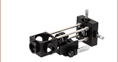
Click to Enlarge
Output Beam Circularization and Collimation Setup
- 500 ± 100 ps Pulse Duration
- 515 nm Center Wavelength
- 16 - 20 µJ Typical Pulse Energy
- Laser Head and Controller Included
The QSL52A Q-Switched Picosecond Microchip Laser has a compact design and provides 500 ± 100 ps pulses at 515 nm with a typical average output power of 175 - 225 mW. The typical pulse train has 16 - 20 µJ of energy per pulse with a peak pulse power of >30 kW at a repetition rate of 9 - 13 kHz. Note that each laser has a fixed average output power, repetition rate, pulse duration, and pulse energy, but these values vary within the specified range from device to device.
The laser head features 4-40 threads for compatibility with our 30 mm cage components as well as SM05 (0.535"-40) internal threading on the beam aperture. This compatibility allows for easy integration of external optics to collimate the weakly divergent output beam. The output beam has an ellipticity of >0.65 (see the Specs tab for a typical beam profile), but it can be circularized using cylindrical lenses; the recommended setup is shown in the image to the right.

 Zoom
Zoom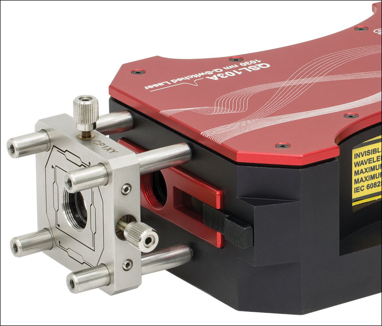
Click to Enlarge
An AC127-075-B achromatic doublet lens is mounted on the QSL103A laser head using a CP1XY cage plate and ER1.5 cage rods.
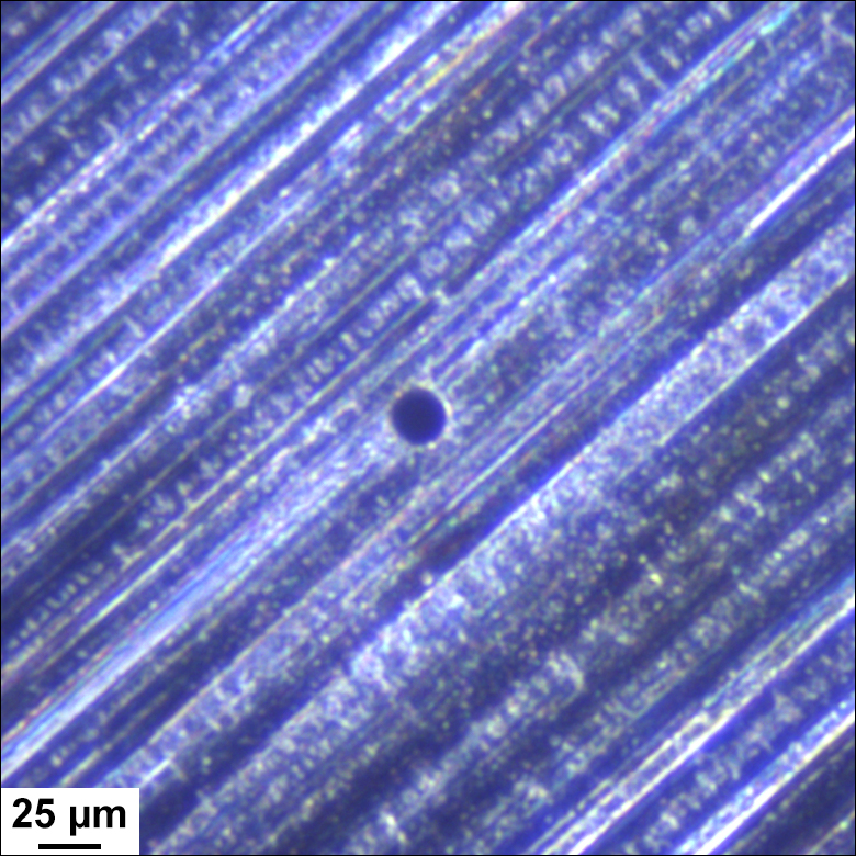
Click to Enlarge
Laser-Drilled Hole Through a 100 µm Thick Aluminum Sheet Created Using a QSL103A Laser
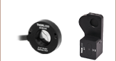
- Sub-ns Pulse Duration
- Center Wavelength: 1030 nm or 1064 nm
- µJ-Level Typical Pulse Energies:
- QSL103A: 35 - 50 µJ
- QSL106B: 1.7 - 2.2 µJ
- Laser Head and Controller Included
These near-infrared Q-Switched Picosecond Microchip Lasers have a compact design. The QSL103A laser provides 500 ps ± 100 ps pulses at 1030 nm with a typical average output power of 350 - 450 mW, and the QSL106B provides 550 ± 100 ps pulses at 1064 nm with a typical average output power of 150 - 250 mW. The typical QSL103A laser pulse train has 35 - 50 µJ of energy per pulse with a peak pulse power of >65 kW at a repetition rate of 8 - 10 kHz, while the typical QSL106B laser pulse train has 1.7 - 2.2 µJ of energy per pulse with a peak pulse power of >2.5 kW at a repetition rate of 80 - 120 kHz. These lasers can be amplified by using the output as an input seed to our Ytterbium-Doped Fiber Amplifiers. Note that each laser has a fixed average output power, repetition rate, pulse duration, and pulse energy, but these values vary within the specified range from device to device.
Each laser head features 4-40 threads for compatibility with our 30 mm cage components as well as SM05 (0.535"-40) internal threading on the beam aperture. This compatibility allows for easy integration of external optics to collimate the weakly divergent output beam.

 Zoom
Zoom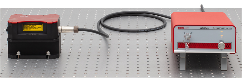
Click to Enlarge
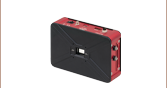
The QSL106B laser head is fixed to a QSLB1 Base and Riser, increasing the beam height.
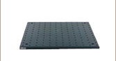
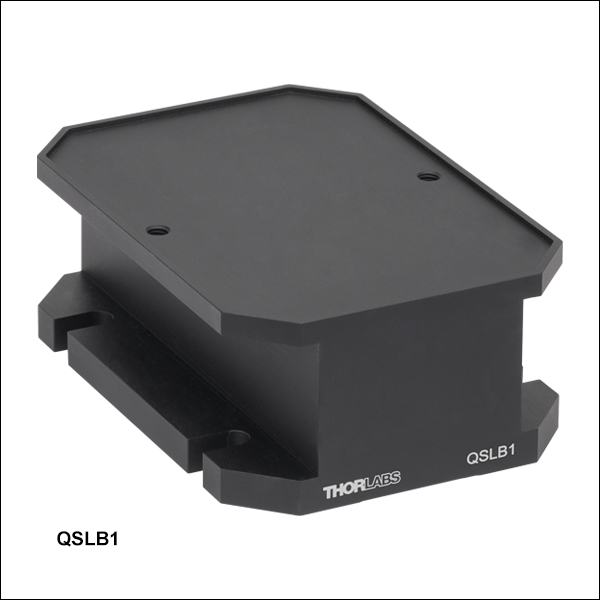
- Raises Laser Beam Height to 2.95" (75.0 mm)
- Provides Thermal Stability
- Mounts Directly to Imperial and Metric Optical Tables
The QSLB1 Base and Riser is an aluminum block that raises the beam height of our Q-Switched Microchip Laser Systems to 2.95" (75.0 mm) while also providing thermal stability to the output. The base features two M6 x 1.0 tapped holes for securing the laser head; two M6 x 14 cap screws (4 mm hex) are included with each base. For mounting to the optical table, the base also has four clearance slots for 1/4"-20 (M6) cap screws.