 Products Home / Optical Systems / Objective Lenses, Scan Lenses, and Tube Lenses / F-Theta Scan Lenses
F-Theta Scan Lenses
- Scan Lenses for Laser Marking, Engraving, and Cutting Systems
- 1064 nm Design Wavelength
- Focal Length: 100 mm, 160 mm, or 254 mm
- Galvo Mounting Bracket Available
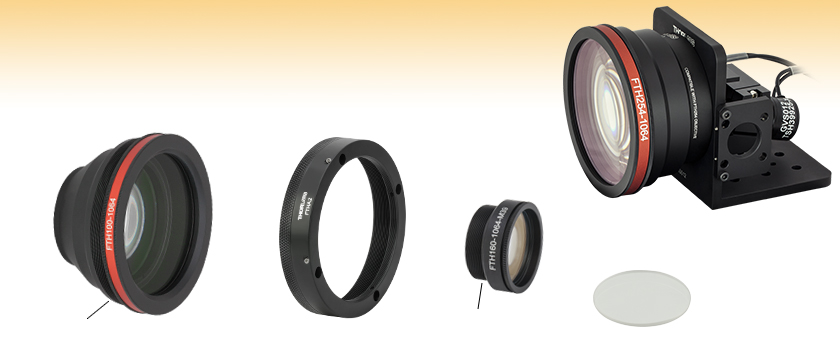
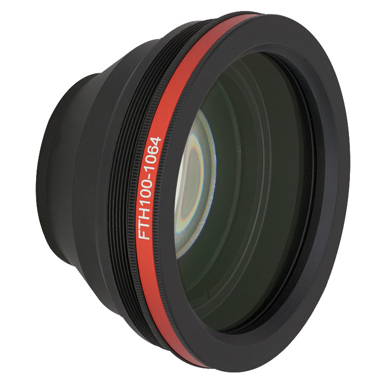
FTH100-1064
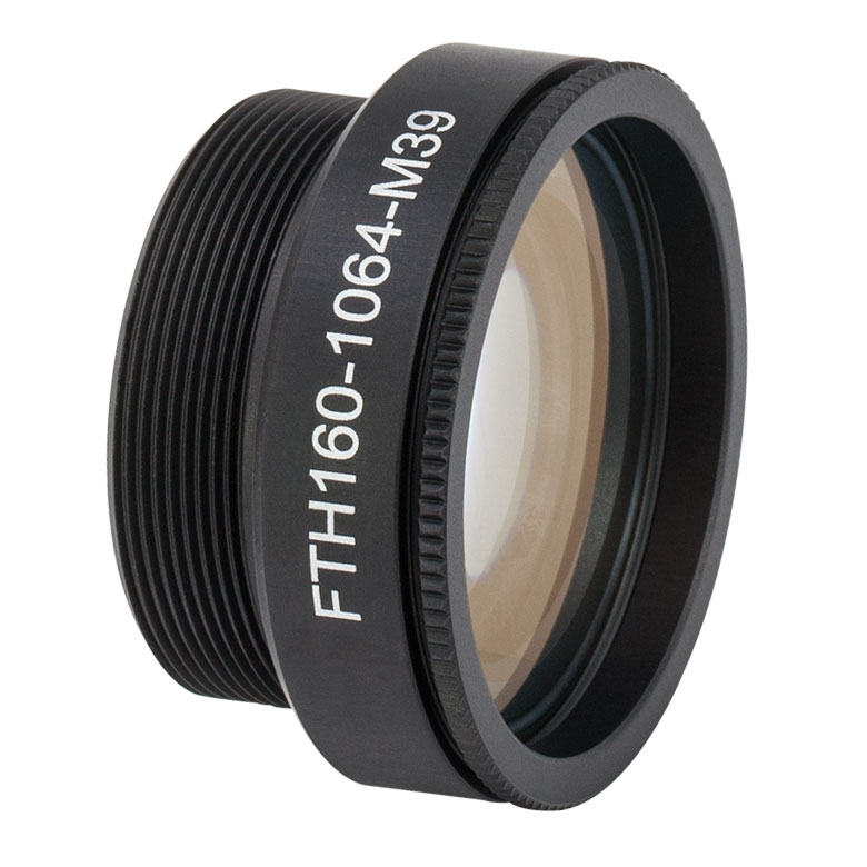
FTH160-1064-M39
M85 x 1.0 Thread
M39 x 1.0 Thread
FTH254-1064 Lens and
GVS012 Galvo Mirror
Pair in a GAS012
Mounting Bracket
FTHW42-1064
Replacement Protective
Window
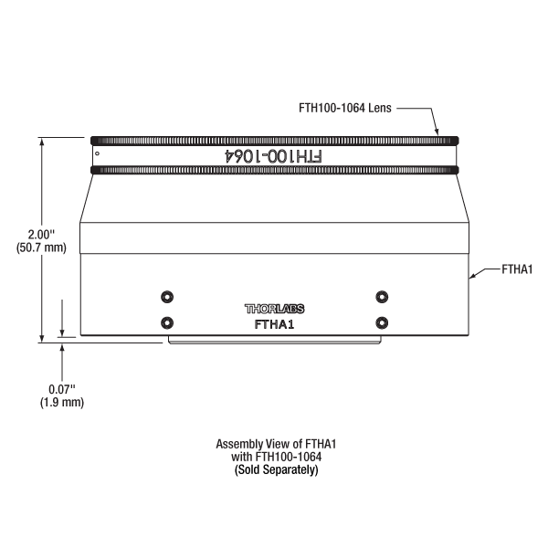
FTHA1
60 mm Cage System or
SM3 Lens Tube Adapter


Please Wait
| Objective Lens Selection Guide |
|---|
| Objectives |
| Super Apochromatic Microscope Objectives Microscopy Objectives, Dry Microscopy Objectives, Oil Immersion Physiology Objectives, Water Dipping or Immersion Phase Contrast Objectives Long Working Distance Objectives Reflective Microscopy Objectives UV Focusing Objectives VIS and NIR Focusing Objectives |
| Scan Lenses and Tube Lenses |
| Scan Lenses F-Theta Scan Lenses Infinity-Corrected Tube Lenses |
Click to Enlarge
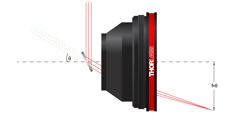
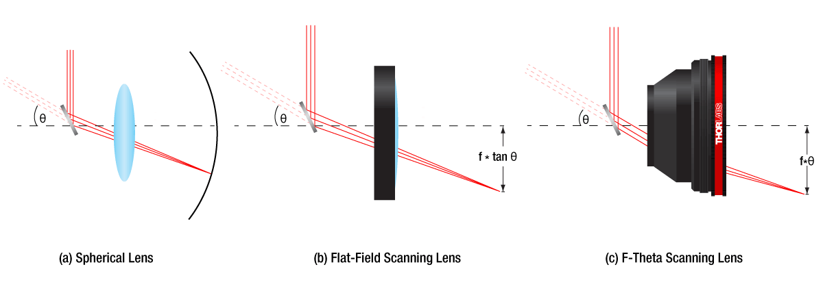
Figure 1.1 In an f-theta lens, the output beam displacement is proportional to the product of focal length f and scan angle θ. For more details, please see the F-Theta Tutorial tab.
 Zemax Files Zemax Files |
|---|
| Click on the red Document icon next to the item numbers below to access the Zemax file download. Our entire Zemax Catalog is also available. |
Features
- 1064 nm Design Wavelength for Nd:YAG Laser Systems
- Flat Field at the Image Plane
- Large Scan Fields Ranging from 70 mm x 70 mm to 156.7 mm x 156.7 mm
- F-Theta Distortion of <0.1% or <1.3%
- M85 x 1.0- and M39 x 1.0-Threaded Versions Available
- Air-Spaced Design
- All Optical Elements are AR Coated
- Accessories Available Below:
- Replacement Protective Glass Windows
- Galvo Mirror Mounting Bracket
- Mounting Adapters for 60 mm Cage Systems, Ø2" Lens Tubes, or Ø3" Lens Tubes
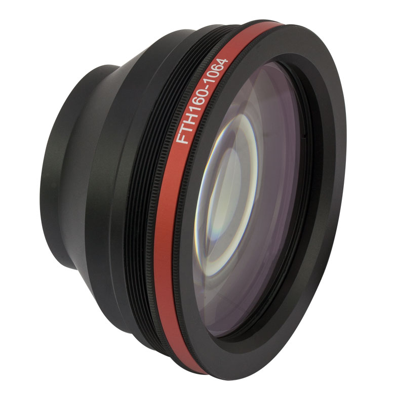
Thorlabs' F-Theta Lenses consist of an air-spaced 2- or 3-element design and are available with one of three focal lengths: 100 mm, 160 mm, or 254 mm. The elements are coated with a high efficiency AR coating for a 1064 nm Nd:YAG laser and for a visible alignment laser (refer to the Graphs tab for details). Each housing has a standard M85 x 1.0 or M39 x 1.0 thread for compatibility with most commercial laser marking systems, including ScanLAB, TRUMPF, and Datalogic, as well as a protective glass window that can be easily changed using the instructions provided below. Replacement AR-coated protective windows are also available.
Click to Enlarge
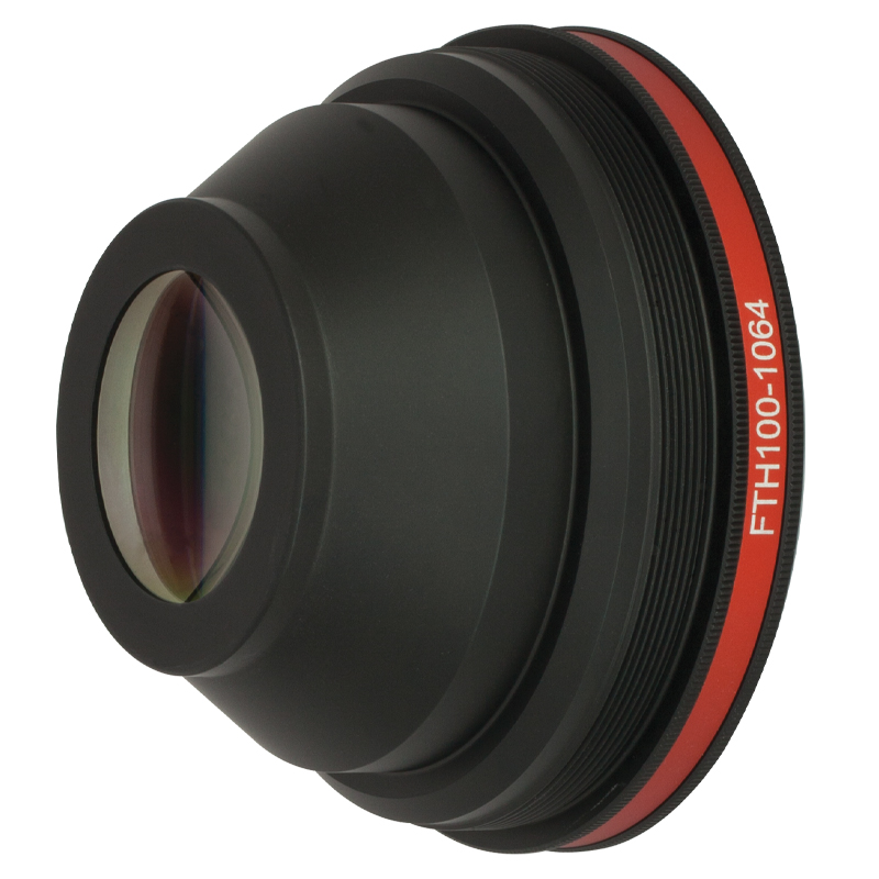
Figure 1.2 FTH100-1064 Rear View
F-theta lenses are the standard lenses for galvo-scanner-based laser marking, engraving, and cutting systems. The diffraction-limited, multiple-element, air-spaced lens design is optimized for a flat field in the image plane and low f-theta distortion. In an f-theta lens, the output beam displacement is equal to f*θ, where θ is the angle of incidence of the input beam (see Figure 1.1). Thus, the input beam and output beam angular velocities are directly proportional, allowing the scanning mirrors to run at a constant angular velocity, greatly simplifying control electronics. For more details on f-theta lenses, please see the F-Theta Tutorial tab.
Mounting Options
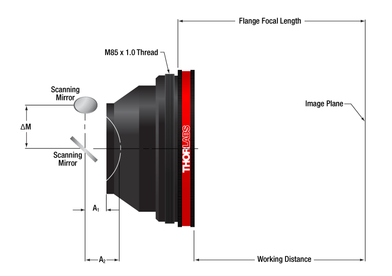
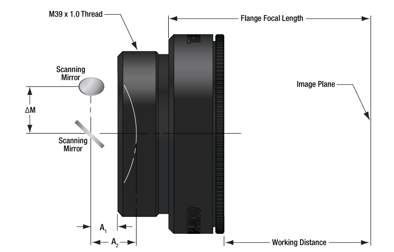
These f-theta lenses are compatible with our Large Beam Galvo Mirror Systems. We also offer the GAS012 Mounting Bracket, sold below, which allows our f-theta lenses to be mounted at the proper distance from our galvo mirrors. Alternatively, we offer adapters for mounting our FTH100-1064, FTH160-1064, and FTH254-1064 lenses to 60 mm Cage Systems or SM3 (3.035"-40) Lens Tubes. The FTH160-1064-M39 F-Theta Lens can be adapted to our SM2 (2.035"-40) Lens Tubes using our SM2A29 External SM2 to Internal M39 x 1.0 thread adapter.
Click to Enlarge
Figure 1.4 FTH160-1064-M39 Schematic
The shaded regions of the plots are the wavelength ranges over which the coating is specified: 450 nm - 700 nm (Ravg < 1.0% per surface) and 1020 nm - 1080 nm (Ravg < 0.3% per surface). Performance outside of these ranges is not guaranteed. The visible AR coating range is intended to allow use with an alignment laser. The other lens specifications are not optimized for performance at visible wavelengths.
Click to Enlarge
Click Here for Raw Data
The FTH100-1064, FTH160-1064, and FTH254-1064 lenses all have three optical elements, not including the protective window. The FTH160-1064 and FTH254-1064 lenses have similar transmission to the plot shown above, only differing due to different element thicknesses.
F-Theta Lenses
F-theta lenses have been engineered to provide the highest performance in laser scanning or engraving systems. These lenses are ideal for engraving and labeling systems, image transfer, and material processing. For many applications in laser scanning and engraving, a planar imaging field is desired for the best results. A spherical lens can only image along a circular plane [see Figure 3.1 (a)]. The flat-field scanning lens solves this problem. However, the displacement of the beam depends on the product of the effective focal length (f) and the tangent of the deflection angle θ [f × tan (θ), see Figure 3.1 (b)].
While this nonlinear displacement can be accounted for with the proper software algorithm, the ideal solution is to produce a linear displacement (i.e., constant scan rate). F-theta lenses are designed with a barrel distortion that yields a displacement that is linear with θ [f*θ, see Figure 3.1 (c)]. This simple response removes the need for complicated electronic correction and allows for a fast, relatively inexpensive, and compact scanning system.
Click to Enlarge
Figure 3.1 Scanning Lenses
F-theta lenses solve many of the problems associated with laser scanning. Additionally, the compact design of the f-theta lens allows the user to reduce the number of optical components needed to provide a flat image plane. These lenses are able to realize tighter spot sizes, which translate into higher resolution for scanning or printing, as well as higher intensity for engraving or welding. Most importantly, the spot size (resolution and intensity) are nearly constant across the entire image plane.
Scan Lens Setup
Laser scanning systems are optimized for precision control of a laser’s beam waist size (diameter of the focused spot) and the accurate position of that waist. Typically a laser scanning system will incorporate one or two scan mirrors, depending on function. For instance, in a single mirror system, the mirror will be placed at the entrance pupil position of the f-theta lens. In a two mirror system, the entrance pupil of the f-theta lens is placed between the two mirrors. To maximize the performance of the f-theta lens, the mirror separation should be minimized.
Scan Lens Characteristics
Some of the most important factors to consider when selecting a f-theta lens are operating wavelength, spot size, and scan field diameter (SFD). Through these parameters, the user may then place further constraints upon a scanning system such as entrance beam diameter, scanning mirror deflection, mirror placement, and mirror position.

Scan Field Diameter (SFD), or Scan Length, is the diagonal length of a square area in the image plane where the beam can be focused by the lens. This specification helps define deflection (along with the focal length). Output Scan Angle (OSA) is the angle between the output laser beam after it has passed through the scan lens and the normal of the image plane. The OSA will vary across the image field, although for scanning or engraving the change in OSA will not largely impact dynamics. It should be noted that the OSA is always zero for telecentric lenses. Back Focal Length (BFL) is the distance between the apex of the physical lens (outer glass element) to paraxial focus point. Back Working Distance (BWD) is simply the distance between the housing of the lens to the paraxial focus point.
Another important parameter to consider is field distortion and curvature. While f-theta lenses are well designed to provide a flat image plane, a real lens rarely measures up to the theoretical. There will be some amount of distortion and curvature. Figure 3.2 shows these parameters for our FTH100-1064 f-theta lens, where focal length is 100 mm and the maximum deflection angle is 28°. Figure 3.2 shows both the field curvature in millimeters and f-theta distortion in percent as a function of scan angle. Typically in constructing a scanning system, it is best to place the zero-curvature point at the midrange of the scan to help limit the amount of curvature realized during the scan.
Summary
As stated previously, the goal of the laser system is to produce a spot size appropriate for the necessary resolution and to accurately position that spot anywhere in a flat image plane. Diffraction-limited scanning lenses, in general, will produce a spot size given by

where Spot Size is the 1/e2 beam diameter, λ is the wavelength of the laser, f is the effective focal length of the lens, and A is the entrance beam diameter. C is a constant that relates to the degree of pupil illumination and input truncation (for a Gaussian beam, C = 1.83 when the entrance beam is truncated at the 1/e2 diameter).
The focal length also influences the diameter of the scan field, which is given by

where L is the diagonal of the square scan field, θ is the maximum deflection angle in radians, and again f is the effective focal length of the lens. By maximizing θ, the focal length can be minimized in a system. In general this is the preferred method of maintaining L since it will reduce the necessary size of the optics resulting in a more compact and cost effective system. Additionally, f-theta distortions caused by motor instabilities of the scanning mirrors will be reduced since these distortions scale with the EFL (smaller EFL results in smaller distortions).
| Posted Comments: | |
christiaan van den Berg
(posted 2022-11-25 14:00:25.87) The lens is designed for 1064nm wavelength.
I am considering to use it for 532nm wavelength. Do you have performance data of this lens for this wavelength? cdolbashian
(posted 2022-11-28 12:42:18.0) Thank you for your inquiry Christiaan. While we do not have this type of data presented, using the Zemax blackbox file on our website, you can change operational parameters to simulate the performance at 532nm for any of our components. I have contacted you directly to discuss this. user
(posted 2021-08-11 11:16:43.17) Can't find the F-Theta lens D.O.F like FTH160-1064 FTH100-1064 FTH254-1064; Please show me cdolbashian
(posted 2021-09-29 10:13:27.0) Thank you for reaching out to us here at Thorlabs. We have calculated approximate D.O.F for each of the requested lenses.
All were calculated using 1064nm as wavelength
FTH100-1064 :190um with incoming beam diameter of 12mm
FTH160-1064-M39: 1.1mm with incoming beam diameter of 8mm
FTH160-1064 : 500um with incoming beam diameter of 12mm
FTH254-1064 : 450um with incoming beam diameter of 20mm
I do not have your contact information to discuss this further, but hopefully this helps. Feel free to contact us directly via Techsupport@thorlabs.com with further inquiries. David Willis
(posted 2021-03-17 09:56:10.51) Do you have f-theta lenses for 3rd harmonic Nd lasers? I see galvo scanners for the 3rd harmonic (355 nm), but no corresponding f-theta lenses. I am specifically interested in 349 nm for a Nd:YLF. YLohia
(posted 2021-03-18 02:37:15.0) Hello, thank you for contacting Thorlabs. Unfortunately, we don't offer such an f-theta lens at the moment. ning xu
(posted 2020-09-26 14:43:16.027) 请问是否有f-θ透镜的光路图,或者光路实物图,最好在显微成像系统中。光路有点相像不明白,不知道该怎么安装,调节。谢谢!
https://www.thorlabschina.cn/newgrouppage9.cfm?objectgroup_id=6430 YLohia
(posted 2020-09-28 08:35:24.0) Hello, thank you for contacting Thorlabs. An applications engineer from our team in China (techsupport-cn@thorlabs.com) will reach out to you directly to discuss this. user
(posted 2020-07-27 14:41:04.697) I would like to know about OSA of f theta lens FTH160-1064. Would you please show me the graph of OSA about FTH160-1064?
x axis: sgittal/tangential distance(mm)
y axis: OSA(radian or degree) nbayconich
(posted 2020-07-29 08:28:36.0) Thank you for contacting Thorlabs, the OSA or Output Scan Angle is the angle between the output laser beam after it has passed through the scan lens and the normal of the image plane. The field position of the focused source can be determined by the equation F*Θ where Θ is the OSA after the f-theta lens.
Please see our OSA tutorial below.
https://www.thorlabs.co.jp/newgrouppage9.cfm?objectgroup_id=6430&tabname=f-theta%20tutorial jysohn
(posted 2018-02-05 23:56:44.083) Hi,
My name is Jin Sohn, optical engineer in SD Optics, Inc.
I would like to know about the optical design of the your f-theta lenses, especially, FTH100-1064
Is it designed only for 1064nm or broadband applications?
if possible, can I have optical design files with code v format or zemax format?
Thanks,
Jin. tfrisch
(posted 2018-02-06 09:28:09.0) Hello, Thank you for contacting Thorlabs. The F-Theta lenses are designed for laser applications, though the AR coating has <0.3% average reflectance per surface over 1020 nm - 1080nm. It will also allow a visible guide beam, but the design of the lens is not optimized for any visible wavelengths. While we offer Zemax files in the Docs icon below, this is a black box, and the full prescription is considered proprietary. I will reach out to you directly about your application solowing367
(posted 2017-07-20 11:37:09.393) Hope all is well. I am considering using a F-theta lens for a 532nm pulse laser. How would these lenses perform? tfrisch
(posted 2017-07-26 03:15:47.0) Hello, thank you for contacting Thorlabs. I would expect the damage threshold to be lower at 532nm than at 1064nm. I will reach out to you directly to discuss the other performance specs you are looking for. h.wu
(posted 2017-05-28 23:56:07.587) Hello, could you tell me which tube lens can be used to pair with your F-Theta scan lens?
I would like to pair a F-Theta scan lens with a tube lens to build a light sheet microscope since the beam displacement of F-theta lenses is linear with θ. Thank you. tfrisch
(posted 2017-06-22 08:49:22.0) Hello, thank you for contacting Thorlabs. F-Theta Scan lenses provide a flat imaging plane on their own without additional elements. I will reach out to you directly about the needs of your application such as field of view. mskang
(posted 2016-12-22 10:27:27.457) Dear sir,
FTH series is for only 1064nm wavelength in optimization performance as spec.
If I use this item around 532nm visivle wavelength, is the performance of this series bad? tfrisch
(posted 2016-12-28 04:44:55.0) Hello, thank you for contacting Thorlabs. The visible transmission is given because visible alignment beams are common. These F-Theta lenses are designed for use at 1064nm. I will contact you directly about the performance for visible wavelengths. york.tsai
(posted 2016-09-07 12:38:34.01) I wanna to ask some question about F-theta lens.
1. Why EFL is smaller than Working distance.
2. I can calculate the spot position by scan angle and EFL? ex. Y=f*theta tfrisch
(posted 2016-09-08 09:03:14.0) Hello, thank you for contacting Thorlabs. The Working distance is a mechanical spec measured with respect to the housing, while the EFL is an optical spec measured from the principal plane. In this case, the principal plane falls outside the housing. Yes, the beam position will be f*theta as shown in our F-Theta Tutorial tab. hyubkorea
(posted 2016-05-18 08:35:02.077) I am looking for F theta lens covering broad band wavelength range, but I couldn't find proper products. Is there any product working in broad wavelength range which covers from UV to IR? The products are for manufacturing application, so I think aberration and high reflectivity aren't important, and damage threshold is the only issue I concern. If there isn't existing product, is it possible to make customized product? besembeson
(posted 2016-05-19 10:27:38.0) Response from Bweh at Thorlabs USA: We will contact you to further discuss your requirements for a customized solution. vkancharla
(posted 2014-09-04 14:14:19.93) Do you have any data on total transmission of FTH100-1064 at 1030nm? Thank you, VK besembeson
(posted 2014-09-10 03:36:52.0) Response from Bweh: We show the total spectral transmission for the FTH100-1064 at the following link under the "Graphs" tab: http://www.thorlabs.com/newgrouppage9.cfm?objectgroup_id=6430&pn=FTH100-1064#7314.
This should include 1030nm. We also have the excel data below the plot. wutong
(posted 2013-12-27 16:32:43.53) Hello! I cannot open the FTH160-1064 zemax file using my zemax program for its version is zemax-2009-32bit. Could you send me a zmx copy for my edition? Thank you! tcohen
(posted 2014-01-02 04:00:00.0) Response from Tim at Thorlabs: Thanks for contacting us. We're in the process of uploading .zmx files for older Zemax versions to compliment the newer .zar files we currently have available in the product documents. In the meantime, our support engineers (techsupport@thorlabs.com) can convert them. I've sent the file via email for your review. moskalev
(posted 2013-10-11 13:06:00.917) Hello,
Do you have any data on total transmission of FTH254-1064 at 2100nm? What would be lead time for FTH254-1064 lens with custom AR coating for 2100nm and visible (for guide laser beam)?
Thank you,
Igor pbui
(posted 2013-10-28 14:51:00.0) Response from Phong at Thorlabs: The transmission for FTH254 at 2.1 um is about 59%. We will contact you directly to discuss the possibility of offering a custom coated lens. power357753
(posted 2013-05-05 08:57:45.62) i can not open FTH100-1064 zemax file ,i want to open it by zemax2005 .could you send me a copy? jlow
(posted 2013-05-09 16:29:00.0) Response from Jeremy at Thorlabs: It seems that the current Zemax file on the website is not compatible with your version. I will get in contact with you for a copy for your edition. |
| Item # | FTH100-1064 | FTH160-1064-M39 | FTH160-1064 | FTH254-1064 |
|---|---|---|---|---|
| Photo - Not to Scale (Click to Enlarge) |
 |
 |
 |
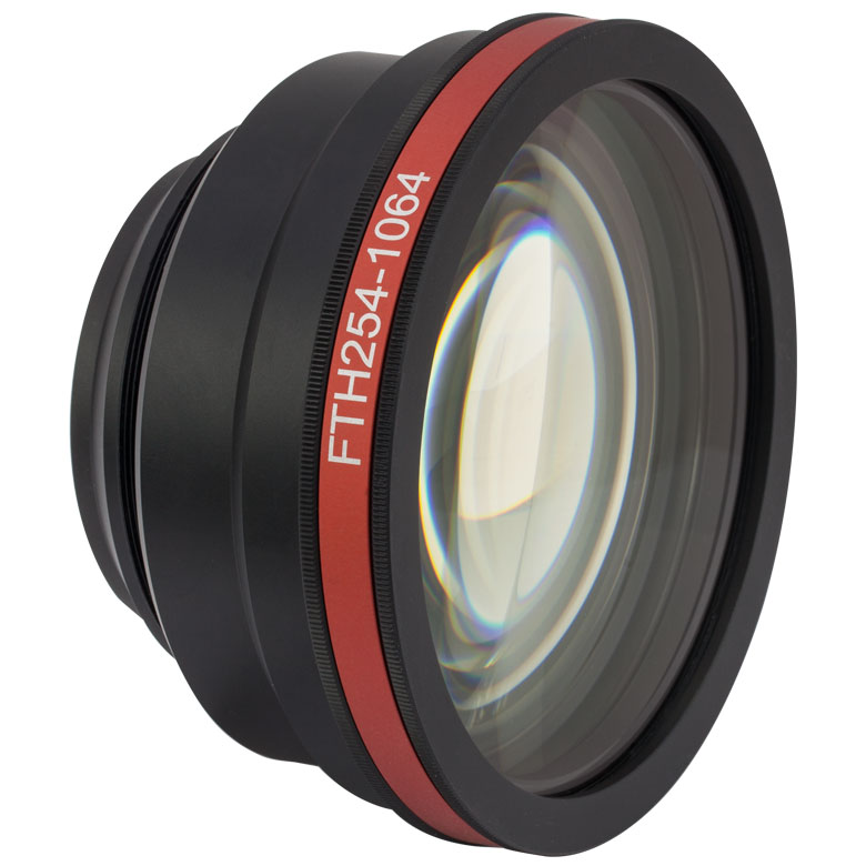 |
| Effective Focal Length (EFL) | 100 mm | 160 mm | 160 mm | 254 mm |
| Scan Angle (Max) | ±28° | ±20° | ±28° | ±25° |
| Scan Length (Max) | 98 mm | 111.7 mm | 156.4 mm | 221.7 mm |
| Scan Field (Max) | 70 mm x 70 mm | 79 mm x 79 mm | 110.6 mm x 110.6 mm | 156.7 mm x 156.7 mm |
| Beam Diametera | 12 mm | 8 mm | 12 mm | 20 mm |
| Spot Size (Diffraction Limited) | 16 µm | 39 µm | 26 µm | 25 µm |
| F-Theta Distortion (Max) | 0.1% | 1.3% | 0.1% | 0.1% |
| Field Curvature and F-Theta Distortion Graphs (Click to View) |
||||
| Working Distancea | 97.8 mm | 181.0 mm | 182.5 mm | 301.2 mm |
| Flange Focal Lengtha | 107.0 mm | 194.1 mm | 191.7 mm | 348.5 mm |
| A1a (Typical) | 7 mm | 8.3 mm | 7.5 mm | 11.5 mm |
| A2a (Typical) | 15 mm | 12.7 mm | 12.3 mm | 20.5 mm |
| ΔMa (Typical) | 20 mm | 10 mm | 20 mm | 30 mm |
| Number of Elements | 3 Plus Protective Window | 2 Plus Protective Window | 3 Plus Protective Window | 3 Plus Protective Window |
| AR Coatingb | 1020 nm - 1080 nm: Ravg < 0.3% (per Surface) 450 nm - 700 nm: Ravg < 1.0% (per Surface) |
|||
| Damage Threshold | 5 J/cm2 (1064 nm, Ø1 mm, 10 ns, 10 Hz) | |||
| Lens Length | 50.7 mm (2.00") | 12 mm (0.47") | 50.2 mm (1.98") | 67.8 mm (2.67") |
| Lens Housing Diameter at Largest Point | Ø90 mm (Ø3.54") |
Ø47.0 mm (Ø1.85") |
Ø90 mm (Ø3.54") |
Ø120 mm (Ø4.72") |
| Mounting Threads | M85 x 1.0 | M39 x 1.0 | M85 x 1.0 | M85 x 1.0 |
| Replacement Protective Window Item #c | FTHW75-1064 | FTHW42-1064 | FTHW75-1064 | FTHW110-1064 |

 Zoom
Zoom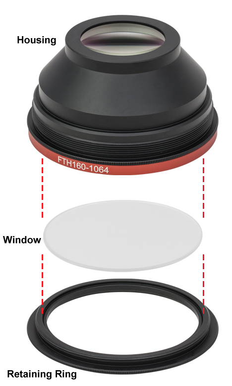
Click for Details
Figure G2.1 Changing the Window of an F-Theta Scan Lens
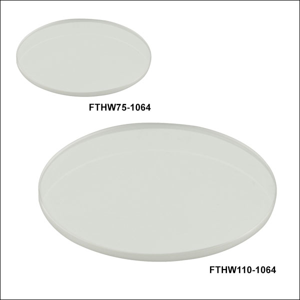
- Replacement Protective Windows for F-Theta Scan Lenses
- Available with Ø42 mm, Ø75 mm, or Ø110 mm
- Easy to Install
Replacement protective windows for the f-theta scan lenses sold above are available here. The windows have an AR coating optimized for 1064 nm (the design wavelength of the f-theta lenses) and the 450 to 700 nm range (allowing a visible laser to be used for alignment purposes).
To change a window, unscrew the front retaining ring from the larger aperture of the f-theta lens. After removing the old window, hold the retaining ring so that the threaded side is facing up (see Figure G2.1). Place the new protective window inside the recessed area in the center of the ring. Hold the f-theta lens housing so that the large aperture is facing downwards, and screw the retaining ring back into the housing to secure the window.
| Table G2.2 Specifications | |||
|---|---|---|---|
| Item # | FTHW75-1064 | FTHW42-1064 | FTHW110-1064 |
| Compatible Lenses | FTH100-1064, FTH160-1064 | FTH160-1064-M39 | FTH254-1064 |
| Diameter | 75 mm (2.95") | 42 mm (1.65") | 110 mm (4.33") |
| Diameter Tolerance | +0 mm / -0.1 mm | +0 mm / -0.15 mm | +0.5 mm / -1.0 mm |
| Thickness | 2.0 mm (0.08") | 1.6 mm (0.06") | 3.0 mm (0.12") |
| Thickness Tolerance | ±0.1 mm | ||
| Parallelism | ≤3 arcmin | ≤2 arcmin | ≤3 arcmin |
| Clear Aperture | Ø71 mm | Ø40 mm | Ø104 mm |
| Substrate | N-BK7 | ||
| Surface Quality | 20-10 Scratch-Dig | ||
| Transmitted Wavefront Error (Peak to Valley) |
<1λ @ 633 nm | <1λ @ 633 nm | <1.5λ @ 633 nm |
| AR Coatinga | 1020 nm - 1080 nm: Ravg <0.3% (per Surface) 450 nm - 700 nm: Ravg < 1.0% (per Surface) |
||
| Damage Threshold | 20 J/cm2 (1064 nm, Ø1 mm, 10 ns, 10 Hz) | ||

 Zoom
Zoom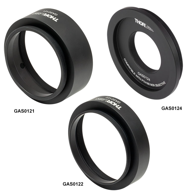
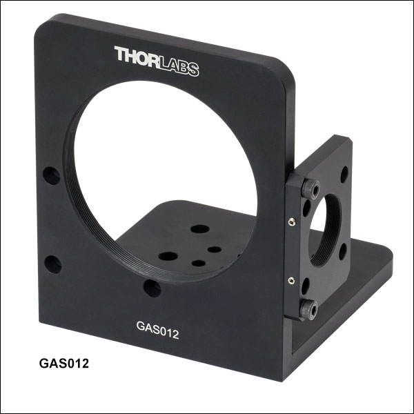
- Mounting Bracket for Integrating our F-Theta Scan Lenses with our Large Beam Galvo Mirror Pair
- Removable 30 mm-Cage- and SM1-Thread-Compatible Input Plate
- Thread Adapters (Sold Below) Required for Attaching F-Theta Lenses
- Compatible with Imperial or Metric Breadboards and Optical Tables
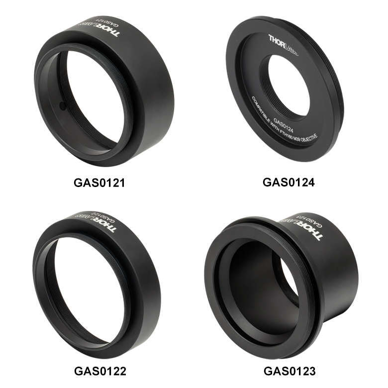
The GAS012 Mounting Bracket allows for the integration of our M85-threaded or M39-threaded f-theta scan lenses with our large-beam-diameter dual-axis galvanometer mirror pairs. It also allows the complete assembly to be integrated with optical-table- or breadboard-based optomechanical setups. To use the GAS012 mounting bracket, a thread adapter (also sold below) must also be purchased. This places the lens at the recommended distance, A1, from the second galvo mirror (see diagrams in the Overview tab). See Table G3.1 for a description of which adapter is compatible with each f-theta lens.
The bracket's input light port is a plate that features both SM1 (1.035"-40) threading and four Ø6 mm cage rod through holes for Ø1" lens tube and 30 mm cage system integration, respectively. The GAS012 bracket has a bottom mounting surface with eight #8 (M4) and nine 1/4" (M6) through holes, spaced at 12.6 mm (0.496") and 25.2 mm (0.99"), respectively, for compatibility with both imperial and metric breadboards and optical tables. When mounted, the GVS012(/M) galvo mirror pair does not sit directly on this surface, allowing all of the through holes to be used for table or breadboard mounting.
| Table G3.1 Adapter Compatibility | |||
|---|---|---|---|
| Mounting Bracket Item # | GAS012 | ||
| Thread Adapter Item # | GAS0121 | GAS0122 | GAS0124 |
| Compatible Scan Lens | FTH100-1064 FTH160-1064 |
FTH254-1064 | FTH160-1064-M39 |
| Compatible Galvo Mirror System | Large Beam Diameter Dual-Axis Galvo Systems | ||
| Assembled System Photo (Click for Details) |
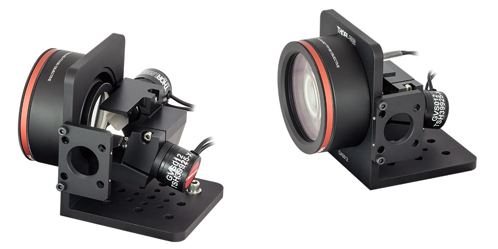 |
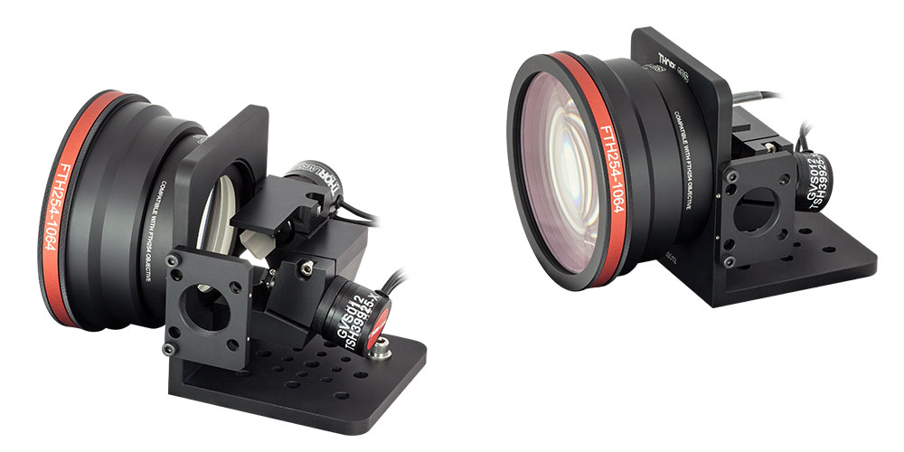 |
 |

 Zoom
Zoom

Click to Enlarge
Figure 535B FTH254-1064 Lens Mounted in 60 mm Cage System Using the FTHA2 Adapter, an LCP34T(/M) Cage Plate, and a Ø1" Pedestal Post

Click to Enlarge
Figure 535A FTH100-1064 Lens Mounted to Ø3" Lens Tube Using the FTHA1 Adapter, an SM3TC Post Mounting Adapter, and a Ø1" Pedestal Post
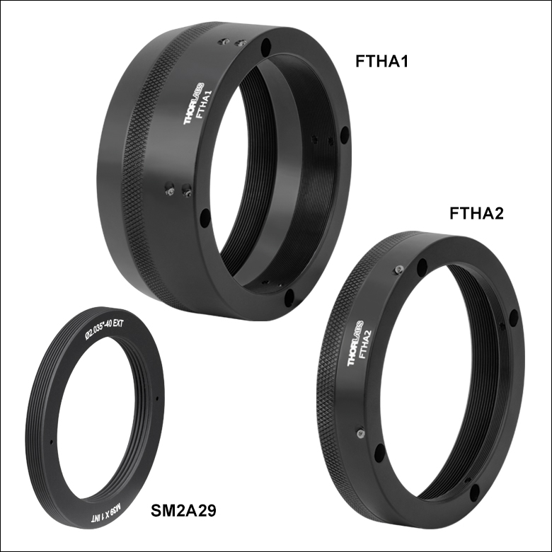
- Integrate an FTH100-1064, FTH160-1064, and FTH254-1064 Lens with a Ø3" Lens Tube or a 60 mm Cage System
- Integrate an FTH160-1064-M39 Lens with a Ø2" Lens Tube
These mounting adapters connect our f-theta scan lenses to our lens tube systems. The SM2A29 adapter offers external SM2 (2.035"-40) threads for mating our
FTH160-1064-M39 F-Theta Lens with an SM2 Lens Tube. The FTHA1 and FTHA2 adapters each feature four bores for Ø6 mm cage rods for integrating with 60 mm cage systems and internal SM3 threads for mounting to Ø3" lens tubes. These support methods cannot be used simultaneously due to mechanical clashing. For compatibility, please see Table 535C.
| Table 535C Adapter Compatibility | |||
|---|---|---|---|
| Adapter Item # |
FTHA1 | FTHA2 | SM2A29 |
| Compatible Scan Lens |
FTH100-1064 FTH160-1064 |
FTH254-1064 | FTH160-1064-M39 |
| Mounting Compatibility |
60 mm Cage Systems Ø3" Lens Tubes |
Ø2" Lens Tubes | |
Note: Due to the mass of our M85 x 1.0-threaded f-theta lenses, we strongly recommend supporting the cage system or lens tube and making the lever arm between the support and the lens as short as possible. For examples, see Figures 535A and 535B.
Assembly Diagrams
Click to Enlarge
Figure 535D FTH100-1064 Lens Mounted in FTHA1 Adapter

Click to Enlarge
Figure 535E FTH160-1064 Lens Mounted in FTHA1 Adapter

Click to Enlarge
Figure 535F FTH254-1064 Lens Mounted in FTHA2 Adapter

Click to Enlarge
Figure 535G FTH160-1064-M39 Lens Mounted in SM2A29 Adapter