 Products Home
Ultra-Thin Edgepass Filters
- Ultra-Thin Longpass and Shortpass Filters
- Constructed of PMMA/Acrylic Layers
- ODavg > 4 In Rejection Region
- Tavg > 80% in Transmission Region
FESU550
Ultra-Thin Shortpass Filter Cut-Off: 550 nm
FESU600
Ultra-Thin Shortpass Filter Cut-Off: 600 nm
FELU900
Ultra-Thin Longpass Filter Cut-On: 900 nm
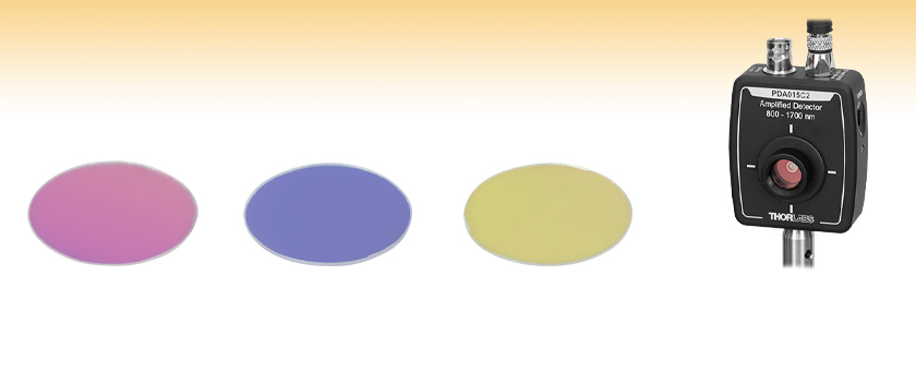
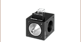
Application Idea
FELU800 Longpass and FESU850 Shortpass Filters Stacked in an SM05L03 Lens Tube and Mounted on a PDA015C2 Detector


Please Wait
| Table 1.1 Common Specifications | |
|---|---|
| Peak Optical Density at Center Wavelength | >4.0 |
| Clear Aperture | Ø ≥ 11.3 mm (Ø 0.44") |
| Thickness | <0.3 mm |
| Substratea | PMMA/Acrylic |
| Surface Quality | 60-40 Scratch-Dig |
| Cut-On or Cut-Off Tolerance | ±2% of Cut-off λ |
| Construction | Polymer Preform Heated and Pulled then Cut Into Filters |
| Slope Toleranceb | <3.0% |
Packaging Redesign
Thorlabs is investing in green initiatives to replace plastic and foam optics packaging with more sustainable solutions. Leave feedback or learn more about what went into the design of our pilot program for optics here.

Click to Enlarge
Our new case is made from recyclable steel and includes recyclable paper inserts to protect the optic inside.

Features
- 12.5 mm Outer Diameter, <0.3 mm Thick Longpass and Shortpass Filters
- ODavg > 4 in Rejection Region
- Ultra-Thin and Lightweight Construction Ideal for Integration into Portable Devices
- Ideal as Raman Spectroscopy Filters or Emission Filters for Fluorescence Applications in Compact Systems
- Custom Edgepass Filter Sizes and Shapes are Available by Contacting Tech Sales
Thorlabs offers Ultra-Thin Edgepass Filters that are ideal for isolating regions of a spectrum in compact experimental systems. These filters, manufactured by Everix®†, offer an average optical density (ODavg) in excess of 4 in the rejection region and greater than 80% average transmission in the transmission region. Please see the graphs in Tables G1.1 and G2.1 below for more information on the rejection and transmission regions for these filters.
These filters are primarily composed of poly(methyl methacrylate) (PMMA), also referred to as acrylic glass, which enables them to be directly bonded to other optical components with an acrylic-based optical adhesive or epoxy. This makes these ultra-thin filters ideal for applications in lightweight sensors, miniature diagnostics, and point-of-care diagnostics. Each filter comes in a mesh net for protection, and can be mounted in any SM05 component mount, such as our LMR05 fixed lens mounts or our SCFW6 cage filter wheel. We recommend caution when mounting the filters with retaining rings, as overtightening the rings can damage the filter's external layers.
Due to their size, these optics are best handled with a pair of tweezers. From the PMMA/Acrylic polymer used in these filters, care must be taken to avoid any chemicals that are solvents for PMMA, such as acetone or methanol, as detailed in the Cleaning PMMA/Acrylic Optics section of our Optics Handling and Care Tutorial.
Click to Enlarge
Figure 1.1 Illustration of the Construction Process for Ultra-Thin Filters
Filter Construction
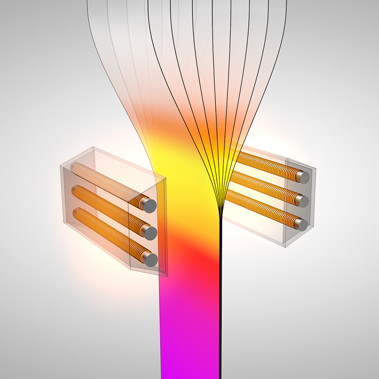
These edgepass filters are formed from a series of very thin PMMA/Acrylic-based polymer layers which are assembled into a larger block of polymers, referred to as a preform. This preform is heated and pulled in one direction, reducing the layer thickness until the layers are thin enough to cause thin film interference between the layers of the polymers. These layers are embedded into a pair of thicker acrylic covers for resistance against scratching and chipping of the surface. The resulting thin sheet is spectrally mapped to measure spectral performance, and the filters are then cut out.
Due to this process, the filters lack a defined substrate. The typical thickness observed in our ultra-thin filters is between 0.1 to 0.3 mm, roughly 6 to 20 times thinner than the 2.0 mm substrate used to form Thorlabs' hard-coated edgepass filters. These ultra-thin filters are slightly bendable and can be 3-D formed to reduce or eliminate angle-of-incident effects on the spectrum. If your application requires a particular bending curvature, please reach out to Tech Support to inquire about custom options.
†Everix is a registered trademark of Everix Optical Filters.
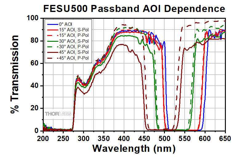
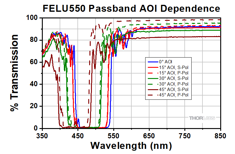
Dependence of Cut-On/Cut-Off Wavelength on Angle of Incidence (AOI)
Thorlabs' ultra-thin filters are intended to be used with collimated light normally incident on the surface of the filter. For uncollimated light or light striking the surface at an angle, the cut-on/cut-off wavelengths will shift towards the UV end of the spectrum and the shape of the transmission region (passband) will change. Measurements of the filter transmission were made at different angles of incidence (AOI) were taken using the same spectrophotometer used to make the on-axis measurements shown in the transmission graphs in tables G1.1 and G2.1. Data was collected for both s- and p-polarized states with transmission plots for select edgepass filters obtained at an AOI of 0°, 15°, 30°, and 45° shown below in Figure 2.1 and Figure 2.2.
Click to Enlarge
Figure 2.1 Plot showing the transmission of an FESU500 shortpass filter at different angles of incidence for s- and p-polarized light.
Click to Enlarge
Figure 2.2 Plot showing the transmission of an FELU550 longpass filter at different angles of incidence for s- and p-polarized light.
Please note: All measured data presented is an example of the performance of our edgepass filters. Performance will vary from filter to filter, especially at off-axis angles of incidence. Plots of transmission and optical density for all filters may be found in Tables G1.1 and G2.1 below.
Transmission Analysis: Optical Density and Slope Tolerance
The transmission and optical density properties of the ultra-thin filters are both measured to determine the transmission and blocking regions of light. The transmission of the filters is measured with collimated light incident normal to the surface, with the optical density calculated through the following equation:
Optical Density Equation:![]()
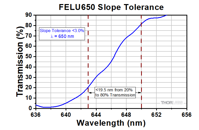
The value of the slope tolerance of Thorlabs' ultra-thin filters is defined as the percentage of the cut-on or cut-off wavelength required to transition from a transmission of 20% to a transmission of 80%. For these filters, the slope tolerance is quoted as <3%, and can be obtained from the transmission data as shown in Figure 2.3.
Click to Enlarge
Figure 2.3 Transmission graph of the FELU650 longpass filter, spanning
7 nm from T ~ 20% to T ~ 80% for a slope tolerance of 1%.
Ultra-Thin Filter Differences
Hard-Coated Filter Structure
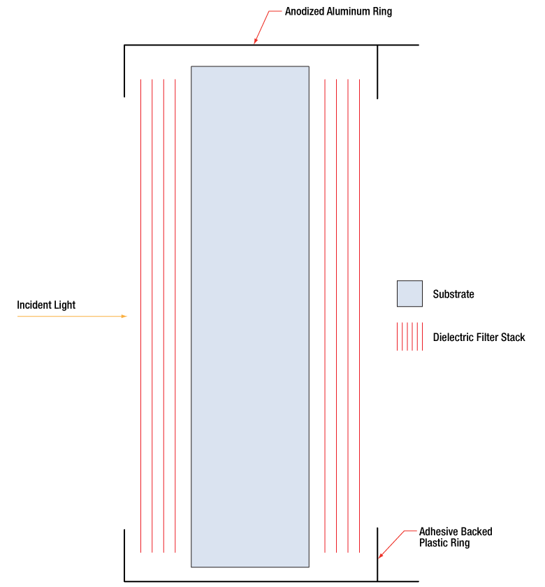 Click to Enlarge
Figure 3.1 A hard-coated filter is deposited onto the substrate surfaces. The number of layers shown in this schematic is not indicative of the number of layers in an actual hard-coated bandpass filter. The drawing is also not to scale.
Ultra-Thin Filter Structure
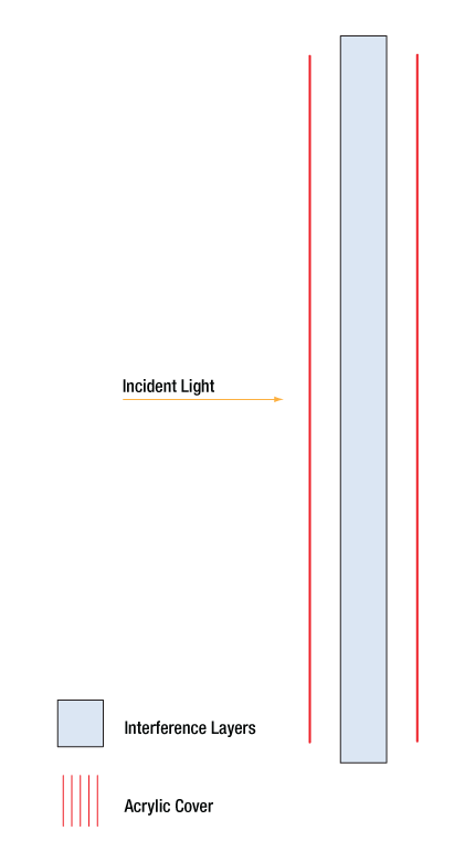 Click to Enlarge
Figure 3.2 An ultra-thin filter is formed from a polymer preform made of hundreds of layers thermally drawn into a thin sheet. Thicker acrylic layers cover the exterior to protect from chipping and breakage. The number of layers shown in this schematic is not indicative of the number of layers in an actual ultra-thin edgepass filter. The drawing is also not shown to scale.
Ultra-thin filters are a new, alternative type of filter to our traditional hard-coated optical filters. Hard-coated filters offer very high durability and transmission performance, and are useful with high-powered optical systems. These ultra-thin filters compromise some optical performance in exchange for an extremely compact design that is useful for integration into smaller systems and enable new applications.
Hard-coated filters are produced by sputtering dielectric layers onto a glass substrate, such as UV fused silica; the dielectric coatings are very durable and can be exposed to the environment without degradation of performance. The film construction is essentially modified quarter-wave stack, using interference effects to isolate spectral bands. The dense coating on these filters allows them to be constructed using a single substrate, as shown in Figure 3.1, which yields a stable, long-lasting, and high-quality optical filter. This process is automated and results in a transmitted wavefront error value that is close to that of an uncoated optic.
Ultra-thin filters are constructed differently, not using sputtering or physical vapor deposition but formed from a series of very thin PMMA/Acrylic-based polymer layers which are assembled into a larger block of polymers, referred to as a preform. This preform is heated and pulled in one direction, reducing the layer thickness further until the layers are thin enough to cause thin film interference. These interference layers are embedded into a pair of thicker acrylic covers for resistance against scratching and chipping of the surface, as shown in Figure 3.2. The resulting thin sheet is spectrally mapped to measure spectral performance, and the filters are then cut out.
Due to this method of construction, the filters lack a substrate and observe a typical thickness between 0.1 and 0.3 mm, roughly 6 to 20 times thinner than the 2.0 mm substrate used to form Thorlabs' hard-coated edgepass filters. The filters are also slightly bendable and can be 3-D formed to reduce or eliminate angle-of-incidence effects on the spectrum. The acrylic material of the ultra-thin filters means that changes in heat and humidity above the softening point of PMMA, roughly 110 - 115 °C, can induce small thickness changes in the polymer layers. These changes in layer thickness can lead to adverse alterations to spectral performance that are possibly permanent, so we recommend storing the filters in environments below ~90 °C.
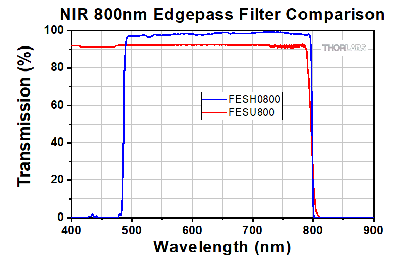
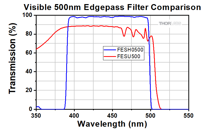
The performance of our ultra-thin edgepass filters is slightly lower than that of our hard-coated edgepass filters, with average transmissions above 80% in their transmission region and an average OD above 4 achieved in their rejection region. As can be seen in Figures 3.3 and 3.4, the hard-coated filters offer a higher performance across the transmission region in both the visible and NIR wavelength regimes, with a flatter transmission evident of the high precision and repeatability of the sputtering process used to make them. The cut-on and cut-off for hard-coated filters is also steeper compared to ultra-thin filters, as shown more closely in Figures 3.5 and 3.6.
 Click to Enlarge
Figure 3.4 NIR Performance Comparison of Hard-Coated
and Ultra-Thin Filters
 Click to Enlarge
Figure 3.3 Visible Performance Comparison of Hard-Coated
and Ultra-Thin Filters
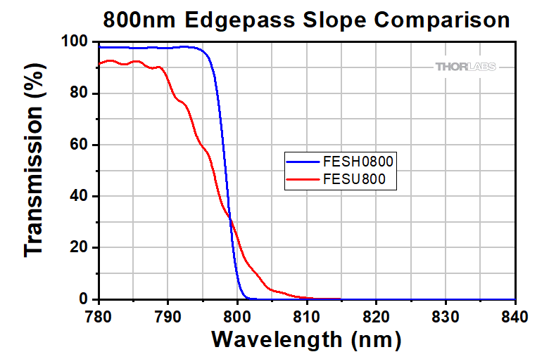 Click to Enlarge
Figure 3.6 NIR Transmission Slope Comparison of Hard-Coated
and Ultra-Thin Filters
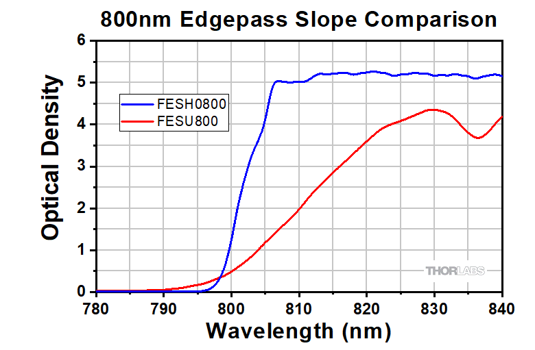 Click to Enlarge
Figure 3.5 NIR Optical Density Slope Comparison of Hard-Coated
and Ultra-Thin Filters
| Posted Comments: | |
| No Comments Posted |
| Table G1.1 Specifications | ||||||
|---|---|---|---|---|---|---|
| Item # | Cut-On Wavelength | Transmission Region (Tavg > 85%) |
Transmission Region (Tabs > 60%) |
Rejection Region (ODavg > 4, ODabs > 2) |
Transmission Dataa |
Diameter |
| FELU450 | 450 ± 9 nm | 465.9 - 1100 nm | 465.9 - 495.1 nm | 378.7 - 434.4 nm | Ø12.5 mm | |
| FELU500 | 500 ± 10 nm | 517.7 - 1100 nm | 517.7 - 550.1 nm | 420.8 - 482.6 nm | Ø12.5 mm | |
| FELU550 | 550 ± 11 nm | 569.4 - 1100 nm | 569.4 - 605.1 nm | 462.9 - 530.9 nm | Ø12.5 mm | |
| FELU600 | 600 ± 12 nm | 621.2 - 1100 nm | 621.2 - 660.1 nm | 504.9 - 579.1 nm | Ø12.5 mm | |
| FELU650 | 650 ± 13 nm | 673.0 - 1100 nm | 673.0 - 715.1 nm | 546.9 - 627.5 nm | Ø12.5 mm | |
| FELU700 | 700 ± 14 nm | 724.8 - 1100 nm | 724.8 - 770.2 nm | 589.1 - 675.7 nm | Ø12.5 mm | |
| FELU750 | 750 ± 15 nm | 776.5 - 1100 nm | 776.5 - 825.2 nm | 631.2 - 723.9 nm | Ø12.5 mm | |
| FELU800 | 800 ± 16 nm | 828.2 - 1100 nm | 828.2 - 880.2 nm | 673.2 - 772.2 nm | Ø12.5 mm | |
| FELU850 | 850 ± 17 nm | 880.0 - 1100 nm | 880.0 - 935.3 nm | 715.3 - 820.5 nm | Ø12.5 mm | |
| FELU900 | 900 ± 18 nm | 931.8 - 1100 nm | 931.8 - 990.2 nm | 757.4 - 868.8 nm | Ø12.5 mm | |
- Click on
 for a plot and downloadable data. Keep in mind that the data given is typical, and performance may vary from filter to filter, particularly outside of the specified region for each filter.
| Table G2.1 Specifications | ||||||
|---|---|---|---|---|---|---|
| Item # | Cut-Off Wavelength | Transmission Region (Tavg > 80%) |
Transmission Region (Tabs > 60%) |
Rejection Region (ODavg > 4, ODabs > 2) |
Transmission Dataa |
Diameter |
| FESU500 | 500 ± 10 nm | 400 - 482.6 nm | 450.1 - 482.6 nm | 517.7 - 575.7 nm | Ø12.5 mm | |
| FESU550 | 550 ± 11 nm | 400 - 530.9 nm | 495.1 - 530.9 nm | 569.4 - 633.3 nm | Ø12.5 mm | |
| FESU600 | 600 ± 12 nm | 400 - 579.1 nm | 540.1 - 579.1 nm | 621.1 - 690.9 nm | Ø12.5 mm | |
| FESU650 | 650 ± 13 nm | 400 - 627.4 nm | 585.1 - 627.4 nm | 673.0 - 748.4 nm | Ø12.5 mm | |
| FESU700 | 700 ± 14 nm | 400 - 675.7 nm | 630.2 - 675.7 nm | 724.8 - 806.0 nm | Ø12.5 mm | |
| FESU750 | 750 ± 15 nm | 400 - 723.9 nm | 675.2 - 723.9 nm | 776.5 - 863.6 nm | Ø12.5 mm | |
| FESU800 | 800 ± 16 nm | 400 - 772.2 nm | 720.2 - 772.2 nm | 828.3 - 921.2 nm | Ø12.5 mm | |
| FESU850 | 850 ± 17 nm | 400 - 820.5 nm | 765.2 - 820.5 nm | 880.0 - 987.7 nm | Ø12.5 mm | |
- Click on for a plot and downloadable data. Keep in mind that the data given is typical, and performance may vary from filter to filter, particularly outside of the specified region for each filter.