 Products Home / Optical Systems / Camera Lenses / Hard-Coated Bandpass Filters for Machine Vision Lenses
Hard-Coated Bandpass Filters for Machine Vision Lenses
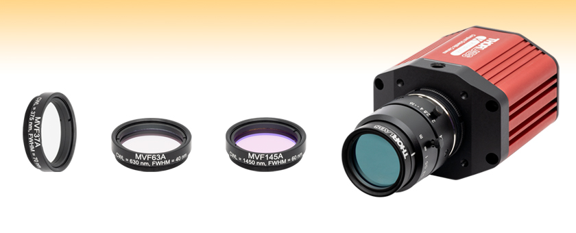
- Mounted Hard-Coated Bandpass Filters for Machine Vision Lenses with M27 x 0.5 Threads
- Center Wavelengths from 375 - 1450 nm
- Ø23.0 mm Clear Aperture
MVF37A
Machine Vision Bandpass Filter, CWL = 375 nm, FWHM = 70 nm
MVF63A
Machine Vision Bandpass Filter, CWL = 630 nm, FWHM = 40 nm
MVF37A
Machine Vision Bandpass Filter, CWL = 1450 nm, FWHM = 60 nm
Application Idea
The MVF63A machine vision filter is attached to an MVL16M23 lens mounted on a CS2100M-USB camera


Please Wait
| Table 1.1 General Specifications | |
|---|---|
| Out of Band Optical Density |
ODabs ≥ 2a |
| Transmission at CWL | ≥92% |
| Transmitted Wavefront Errorb | ≤0.6λ |
| Angle of Incidence | 0° |
| Housing Diameter | 29.0 mm |
| Clear Aperture | Ø23.0 mm |
| Surface Quality | 40-20 Scratch-Dig |
| Coating | Hard Coated |
| Operating Temperature | -50 to 100 °C |
| Storage Temperature | -100 to 200 °C |
| Edge Treatment | Mounted in Black Anodized Aluminum Housing |
| Edge Markings | Item #, Center Wavelength, FWHM |
| Substrate | Eagle XG® Glass |

Features
- Compatible with M27 x 0.5-Threaded Machine Vision Lenses
- ≥92% Transmission at a Range of Center Wavelengths from 375 nm - 1450 nm
- Pass Band Widths from 40 nm - 85 nm
- Designed for Half Cone Angles of ≤20° (or ≤15° for Item # MVF145A)
- Excellent Suppression in Rejection Region
- ODabs ≥ 2, Tavg ≤ 0.1% (375 - 940 nm CWLs)
- ODabs ≥ 3, Tavg ≤ 0.01% (Item # MVF145A)
- Custom Bandpass Filter Sizes are Available by Contacting Tech Sales
Click to Enlarge
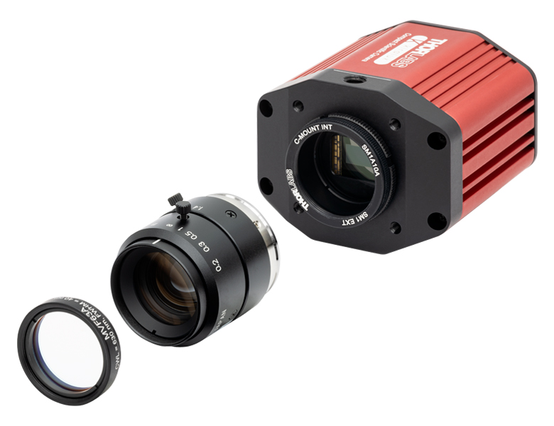
Figure 1.2 An exploded view showing how an MVF63A filter can be mounted to an MVL16M23 lens and then onto a CS2100M-USB camera.
Thorlabs' hard-coated bandpass filters for machine vision, which are designed to provide enhanced spectral isolation of key Yb:YAG, HeNe, Ar, and diode laser lines, offer excellent (ODabs ≥ 2) suppression in the blocking region while providing ≥92% transmission at the design wavelength. They are each mounted in an anodized aluminum housing with M27 x 0.5 external threads for attaching to select machine vision lenses.
The passbands of these filters range from 40 to 85 nm FWHM, depending on the center wavelength chosen, with steep cut-on and cut-off slopes. The center wavelength and passbands for these filters are specified for light normally incident on the surface. For angles of incidence (AOIs) greater than 0°, the band will shift toward a shorter center wavelength and the shape of the passband will change. For more information, see the Tutorial tab.
These bandpass filters feature durable, sputtered coatings on Eagle XG®* glass substrates. They maintain consistent performance over time, even when used in demanding industrial environments. Sputtered thin-film coatings are environmentally stable and resist spectral shifting over time. The dense coating on these filters allows them to be constructed using a single substrate, which yields a stable, long-lasting filter. This coating can withstand the standard optic cleaning procedures; see the Optic Handling and Cleaning Tutorial for more information. Please see the Comparison tab for information about the advantages of hard-coated filters compared to soft-coated filters, such as increased durability and transmission performance. These filters are ideal for factory automation, quality control, robotics, and other machine vision applications that require consistent optical performance.
Each filter is mounted in a black anodized aluminum housing that is labeled with the part number, center wavelength, and full width at half maximum. These filters can be threaded onto our M27 x 0.5-threaded machine vision lenses or any M27 x 0.5-threaded mount. We do not recommend removing the filter from its mount as the risk of damaging the filter is very high.
*Eagle XG® is a registered trademark of Corning, Inc.
Click to Enlarge
Figure 1.3 An OSW22-633E optical switch kit is imaged using a CS165CU1 camera with an MVL8M23 lens and a series of machine vision filters to highlight different features. The images were taken with (a) no filter, (b) an MVF52A filter, (c) an MVF58A filter, and (d) an MVF66A filter.
| Table 1.3 Additional Bandpass Filters | ||||
|---|---|---|---|---|
| UV/VIS Hard-Coated Bandpass Filters 300 - 694 nm CWLs |
NIR Hard-Coated Bandpass Filters 700 - 2000 nm CWLs |
IR Bandpass Filters 1750 - 12 000 nm CWLs |
Wedged Hard-Coated Bandpass Filters 532 - 785 nm CWLs |
Hard-Coated Bandpass Filter Kits |
| We also offer custom bandpass filters with other central wavelengths or FWHM. To request a quote, contact Tech Sales. | ||||

Click to Enlarge
Figure 2.1 The number of layers shown in this schematic is not indicative of the number of layers in an actual hard-coated bandpass filter. The drawing is also not to scale.
Hard-Coated Bandpass Filter Structure
A bandpass filter is created by depositing layers of material on the surface of the substrate. For our hard-coated bandpass filters, the coating is comprised of dielectric stacks alternating with dielectric spacer layers. Each dielectric stack is composed of a large number of alternating layers of low-index and high-index material. The thickness of each layer in the dielectric stack is λ/4, where λ is the design center wavelength of the bandpass filter (i.e. the wavelength designed to have highest transmittance through the filter at normal incidence). The spacer layers are placed in between the stacks and have a thickness of (nλ)/2, where n is an integer. A Fabry-Perot cavity is formed by each spacer layer sandwiched between dielectric stacks. The filter is mounted in an engraved metal ring for protection and ease of handling.
Filter Operation Overview
The constructive interference conditions of a Fabry-Perot cavity allow light at the center wavelength, and a small band of wavelengths to either side, to be transmitted efficiently, while destructive interference prevents the light outside the passband from being transmitted. However, the band of blocked wavelengths on either side of the center wavelength is small. To increase the blocking range of the filter, materials with broad blocking ranges are used as the substrate or to coat the spacer layers. Although these materials effectively block out-of-band transmission of incident radiation, they also decrease the transmission through the filter in the passband.
Filter Temperature
Click to Enlarge
Figure 2.2 This plot displays the forward (solid lines) and backward (dashed lines) transmission through the FBH800-10 and FBH800-40 hard-coated bandpass filters.
The center wavelength of the filter can be tuned slightly (~1 nm over the operating range of the filter) by changing the temperature of the filter. This is primarily due to the slight thermal expansion or contraction of the layers.
Filter Orientation
Direction of Transmission
An engraved arrow on the edge of the filter is used to indicate the recommended direction for the transmission of light through the filter. Orienting the coated side toward the source will reduce unwanted scattering and minimize reflections sent back toward the source. Using the filter in the opposite orientation will not, however, significantly affect the performance of the filter. Figure 2.2 was made by illuminating the filter with a low intensity broadband light and measuring the transmission as a function of wavelength. This plot shows that the direction of transmission through the filter has very little effect on the intensity and the spectrum of the light transmitted through the filter. The minimal variation between the forward and backward traces is most likely due to a small shift in the incident angle of the light on the filter introduced when the filter was removed, flipped over, and replaced in the jig.
Angle of Incidence (AOI)
The filter is intended to be used with collimated light normally incident on the surface of the filter. For uncollimated light or light striking the surface at an angle not normally incident to the surface, the center wavelength (wavelength corresponding to peak transmission) will shift toward lower wavelengths and the shape of the transmission region (passband) will change. Varying the angle of incidence (AOI) by a small amount can be used to effectively tune the passband over a narrow range. Large changes in the incident angle will cause larger shifts in the center wavelength but will also significantly distort the shape of the passband and, more importantly, cause a significant decrease in the transmittance of the passband. Figures 2.3 through 2.6 show examples of the change of the passband, transmission, and center wavelength (CWL) with when the AOI is changed for various filters. Filters with passband full width half maxima (FWHM) in the range of 1 nm to 5 nm are particularly susceptible to these shifts and extra care should be taken to ensure they are set to the desired AOI. Figures 2.3 through 2.6 are given in order of increasing nominal passband FWHM.
Click to Enlarge
Figure 2.4 This plot displays the changing transmission and FWHM of the passband for an FLH1064-3 hard-coated bandpass filter at varying angles of incidence (AOI). The design CWL and passband of the FLH1064-3 filter are 1064 nm and 3 nm, respectively.
Click to Enlarge
Figure 2.3 This plot displays the changing transmission and FWHM of the passband for an FLH532-1 hard-coated bandpass filter at varying angles of incidence (AOI). The design CWL and passband of the FLH532-1 filter are 532 nm and 1 nm, respectively.
Click to Enlarge
Figure 2.6 This plot displays the changing transmission and FWHM of the passband for an FLH1030-10 hard-coated bandpass filter at varying angles of incidence (AOI). The design CWL and passband of the FLH1030-10 filter are 1030 nm and 10 nm, respectively.
Click to Enlarge
Figure 2.5 This plot displays the changing transmission and FWHM of the passband for an FBH800-10 hard-coated bandpass filter at varying angles of incidence (AOI). The design CWL and passband of the FBH800-10 filter are 800 nm and 10 nm, respectively.
Figures 2.7 through 2.11 show how the properties of the FLH532-1, FLH1064-3, and FLH1030-10 hard-coated bandpass filters change as the AOI is varied.

Click to Enlarge
Figure 2.8 This plot shows the the FWHM at the CWL corresponding to the peak transmission at the given AOI. Item #'s FLH532-1, FLH1064-3, and FLH1030-10 have design center wavelengths of 532, 1064, and 1030 nm with 1, 3, and 10 nm FWHM passbands, respectively.

Click to Enlarge
Figure 2.7 This plot displays the transmission at the design center wavelength as the angle of incidence is varied. As can be seen in this graph, the transmission of filters with wider passbands are less sensitive to changes in the AOI. Item #'s FLH532-1, FLH1064-3, and FLH1030-10 have design center wavelengths of 532, 1064, and 1030 nm with 1, 3, and 10 nm FWHM passbands, respectively.

Click to Enlarge
Figure 2.11 This plot displays the center wavelength that provides the maximum transmission for a given angle of incidence for an FLH1030-10 hard-coated bandpass filter with a design CWL of 1030 nm and a passband FWHM of 10 nm.
Click to Enlarge
Figure 2.10 This plot displays the center wavelength that provides the maximum transmission for a given angle of incidence for an FLH1064-3 hard-coated bandpass filter with a design CWL of 1064 nm and a passband FWHM of 3 nm.

Click to Enlarge
Figure 2.9 This plot displays the center wavelength and peak transmission at that wavelength for a given angle of incidence for an FLH532-1 hard-coated bandpass filter with design CWL of 532 nm and passband FWHM of 1 nm.
Filter Reflectance
Thorlabs' hard-coated bandpass filters reflect out-of-band light with high efficiency. Figure 2.12 shows the measured reflectance of an FBH1200-10 hard-coated bandpass filter with a design CWL of 1200 nm and passband FWHM of 10 nm. The blocking region for this filter is specified as ODabs > 5 between the ranges of 200 - 1180 nm and 1220 - 1700 nm.
Click to Enlarge
Figure 2.12 This plot displays the reflectance of an FBH1200-10 hard-coated bandpass filter over an extended range from 200 nm to 1800 nm. As can be seen in the graph, the filter reflectance is high within the blocking region of 200 - 1180 nm and 1220 - 1700 nm. The drop in reflectance below 300 nm is due to increased absorption by the glass substrate.
Out-of-Band Filter Performance
The transmission and optical density properties of the hard-coated bandpass filters will vary for far out-of-band wavelengths. Figures 2.13 and 2.14 show the variation in transmission and optical density for wavelengths far outside the specified blocking regions of 200 - 379 nm and 401 - 1200 nm for an FBH390-10 hard-coated bandpass filter. The FBH390-10 has a design CWL of 390 nm and a passband FWHM of 10 nm. The blocking region is specified to be ODabs > 5 between the ranges of 200 - 379 nm and 401 - 1200 nm.
Click to Enlarge
Figure 2.14 This plot displays the optical density (OD) measured between 200 nm and 1600 nm for the FBH390-10 hard-coated bandpass filter. The OD drops off for wavelengths beyond 1200 nm.
Click to Enlarge
Figure 2.13 This plot displays the transmission through an FBH390-10 hard-coated bandpass filter over an extended range from 200 nm to 1600 nm. The transmission varies for wavelengths beyond 1200 nm.
Hard-Coated Filter Benefits
Soft-Coated Filter Structure
 Click to Enlarge
Figure 24A A soft-coated filter utilizes dielectric stacks sandwiched between substrate layers. The number of layers shown in this schematic is not indicative of the number of layers in an actual bandpass filter, and the drawing is not to scale.
Hard-Coated Filter Structure
 Click to Enlarge
Figure 24B A hard-coated filter is deposited onto the substrate surfaces. The number of layers shown in this schematic is not indicative of the number of layers in an actual hard-coated bandpass filter. The drawing is also not to scale.
Soft-coated and hard-coated filters are commonly sold in the optics industry. Soft-coated filters suffer from poor temperature stability, low transmission, high optical scatter, and a short shelf life owing to their laminate structure of chemically reactive layers. The hard-coated filters do not suffer from these shortcomings as they are formed of chemically inert layers on an optical substrate via a high-energy sputtering technique.
Soft-coated filters are comprised of dielectric layers sandwiched between optical substrates in a housing as shown in Figure 24A. The dielectric layers are often composed of fragile materials such as zinc sulfide, cryolite, or silver. These chemicals react with water, which degrades the performance of the filter, so the shelf life of soft-coated filters is greatly reduced in humid environments. The assembly seals will eventually fail due to the environment, handling, and the construction quality of the filter; the optical performance will rapidly degrade once the seals have failed. Soft-coated filters have a typical lifetime of one to five years in a lab environment owing to these factors.
The laminated structure of the soft-coated filters means that changes in temperature can have a drastic effect on the optical performance of the filter. The dielectric stack, epoxy, optical substrate, absorption glass, and housing may all have different coefficients of thermal expansion. This may result in the shape of the filter changing in unexpected ways with changes in temperature.
Hard-coated filters are produced by sputtering dielectric layers onto a glass substrate; the dielectric filter stack can be exposed to the environment, as shown in Figure 24B, without degradation of performance owing to the material being more environmentally stable than what is used for the soft-coated filters. The hard-coated filters are thinner than soft-coated filters, which allows them to be more easily incorporated into space-limited applications. The sputtering process is automated, highly repeatable, and results in a transmitted wavefront error value that is close to that of the uncoated optic.
The performance of soft-coated filters is limited in the visible wavelengths to approximately 80% transmission if silver is not used and approximately 50% transmission if silver is used in the dielectric stack; the transmission is further limited in the UV. As can be seen in Figure 24C and Figure 24D, the hard-coated filters have improved transmission in the UV and visible wavelength regimes. The cut-on and cut-off for hard-coated filters is relatively steep compared to the soft-coated filters. The transmission is also much flatter for the hard-coated filters compared with the soft-coated, which is due to the sputtering process used that allows more complicated cavity filter designs to be deposited with high precision and repeatability.
 Click to Enlarge
Figure 24D Visible Performance Comparison of Hard- and Soft-Coated Filters
 Click to Enlarge
Figure 24C UV Performance Comparison of Hard- and Soft-Coated Filters
| Posted Comments: | |
| No Comments Posted |
| Table G1.1 Specifications | ||||||||
|---|---|---|---|---|---|---|---|---|
| Item #a | Center Wavelengthb | FWHM Bandwidth |
Blocking Regions (Optical Density, Transmission) | Transmission Datac |
Transmission | Half Cone Angle | Clear Aperture |
Outer Diameter |
| MVF37A | 375 nm | 70 nm | 300 - 328 nm, 415 - 1000 nm (ODabs ≥ 2, Tavg ≤ 0.1%) 1000 - 1100 nm (Tavg ≤ 3.1%) |
≥92%, 345 - 405 nm | ≤20° | Ø23.0 mm | Ø29.0 mm | |
| MVF40A | 405 nm | 40 nm | 300 - 379 nm, 434 - 1050 nm (ODabs ≥ 2, Tavg ≤ 0.1%) | ≥92%, 390 - 420 nm | ||||
| MVF46A | 460 nm | 85 nm | 300 - 406 nm, 507 - 1050 nm (ODabs ≥ 2, Tavg ≤ 0.1%) | ≥92%, 420 - 495 nm | ||||
| MVF52A | 525 nm | 40 nm | 300 - 495 nm, 558 - 1050 nm (ODabs ≥ 2, Tavg ≤ 0.1%) | ≥92%, 510 - 540 nm | ||||
| MVF58A | 585 nm | 40 nm | 300 - 556 nm, 614 - 1050 nm (ODabs ≥ 2, Tavg ≤ 0.1%) | ≥92%, 570 - 600 nm | ||||
| MVF63A | 630 nm | 40 nm | 300 - 601 nm, 660 - 1050 nm (ODabs ≥ 2, Tavg ≤ 0.1%) | ≥92%, 615 - 645 nm | ||||
| MVF66A | 660 nm | 60 nm | 300 - 615 nm, 707 - 1050 nm (ODabs ≥ 2, Tavg ≤ 0.1%) | ≥92%, 635 - 685 nm | ||||
- All specifications are valid for AOI = 0°.
- Transmission at the center wavelength is ≥92% for all our machine vision filters.
- Click on
 for a plot and downloadable data. Please note that transmission is only guaranteed for the specified wavelength and that the data in the plots is typical. Performance may vary from lot to lot.
| Table G2.1 Specifications | ||||||||
|---|---|---|---|---|---|---|---|---|
| Item #a | Center Wavelengthb | FWHM Bandwidth |
Blocking Regions (Optical Density, Transmission) | Transmission Datac |
Transmission | Half Cone Angle | Clear Aperture |
Outer Diameter |
| MVF78A | 785 nm | 40 nm | 300 - 753 nm, 816 - 1050 nm (ODabs ≥ 2, Tavg ≤ 0.1%) | ≥92%, 771 - 799 nm | ≤20° | Ø23.0 mm | Ø29.0 mm | |
| MVF85A | 850 nm | 40 nm | 300 - 817 nm, 885 - 1100 nm (ODabs ≥ 2, Tavg ≤ 0.1%) | ≥92%, 834 - 866 nm | ||||
| MVF94A | 940 nm | 50 nm | 300 - 897 nm, 984 - 1150 nm (ODabs ≥ 2, Tavg ≤ 0.1%) | ≥92%, 920 - 960 nm | ||||
| MVF145A | 1450 nm | 60 nm | 300 - 1372 nm, 1540- 2000 nm (ODabs ≥ 3, Tavg ≤ 0.01%) | ≥92%, 1435 - 1465 nm | ≤15° | |||
- All specifications are valid for AOI = 0°.
- Transmission at the center wavelength is ≥92% for all our machine vision filters.
- Click on for a plot and downloadable data. Please note that transmission is only guaranteed for the specified wavelength and that the data in the plots is typical. Performance may vary from lot to lot.
- Transmitted Wavefront Error (Peak to Valley) at 632.8 nm Over Clear Aperture