 Products Home / Motorized Stages / Motorized Rotation Stages and Mounts / SM2-Threaded Rotation Mount with Resonant Piezoelectric Motors
SM2-Threaded Rotation Mount with Resonant Piezoelectric Motors
- SM2-Threaded Rotation Mount with Closed-Loop Positioning
- Open Frame Design for OEM Applications
- Control via Interface Board, GUI, or ASCII Message Calls
- Fully Integrated Drive Electronics
Application Idea
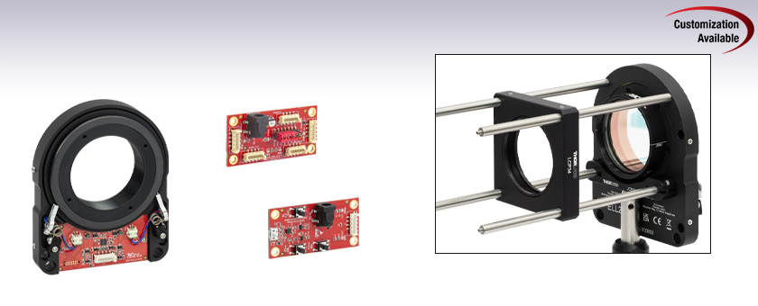
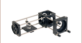
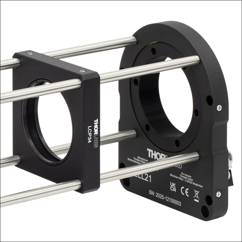
The ELL21K rotates a mounted, SM2-threaded waveplate within a 60 mm cage assembly.
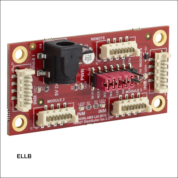
ELLB
Bus Distributor
Interface Board
ELL21K
Rotation Mount
Bundle
(Mount and Board Included)
Rotation Mount for Ø2" or Ø50.0 mm Optics
(Also Available Individually)


Please Wait
| Key Specificationsa | |
|---|---|
| Travel (No Limit Switches)b |
360° Continuous |
| Bidirectional Repeatabilityc | 0.05° (0.87 mrad) |
| Bidirectional Accuracyd | 0.035° (0.61 mrad) |
| Axis Wobblee | 0.032° (0.56 mrad) |
| Max Speedf | 260°/s |
| Max Loadg | Vertical: 100 g (3.5 oz) Horizontal: 300 g (10.6 oz) |
| DC Voltage Input | 4.5 to 5.5 V |
| Minimum Lifetime | 100 km (>403 000 Revolutions) |
| Mount Dimensions |
92.0 x 115.0 x 21.0 mm (3.62" x 4.53" x 0.83") |
| Mount Weight | 260 g (9.2 oz) |
 Thorlabs' Elliptec Technology for OEM
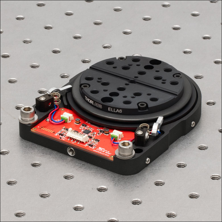
Click to Enlarge
Figure 1.1 ELL21 Mount with ELLA6 Grooved Adapter Plate
Features
- SM2-Threaded Rotation Mount for Ø2" or Ø50 mm Optics
- Ideal for OEMs and Applications Requiring Rapid and Precise Optic Rotation
- Micro-B USB and Picoflex®1 Connectors for Control Signals
- Multi-Drop Serial Communication Protocol Supported
- Absolute Magnetic Encoder Used to Position Mount (Ideal for Light Sensitive Applications)
- Bus Distributor Facilitates Control of up to Four Elliptec® Devices
- Moving World Adapters Attach Using M3 x 0.5 Taps for Additional Mounting Features:
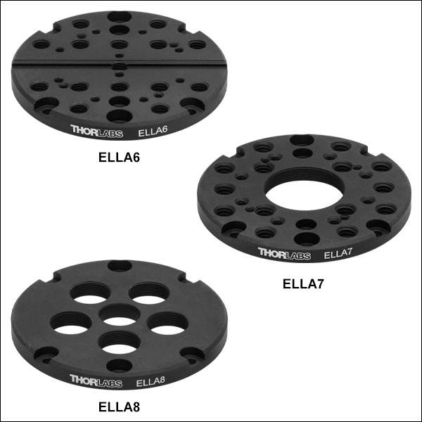
- ELLA6(/M) Adapter with Keyway for Fiber Alignment Accessories
- ELLA7(/M) Adapter with SM1 Threads and Taps for 30 mm Cage Systems
- ELLA8 Adapter with Five SM05-Threaded Holes for Mounted Filters/Optics
- ELLC2 Accessory Upgrade Pack Available Below
Driven by Thorlabs' Elliptec® piezoelectric resonant motor technology, this rotation mount is designed to be a compact solution for applications requiring optic rotation. The rotation mount is offered as a standalone unit (Item #'s ELL21 and ELL21/M), or as part of a bundle (Item #'s ELL21K and ELL21K/M), which also contains an interface board for manual control of the mount, power supply, and cables for connecting the mount and interface board to each other and to a PC. Thorlabs also offers the ELLC2 Accessory Pack which can be used to upgrade standalone units to kits.
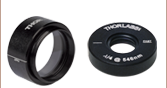
The rotating cell of each mount is internally SM2 (2.035"-40) threaded and includes two SM2RR retaining rings for mounting Ø2" or Ø50 mm optics. It is designed to be lightweight and compact, and the closed-loop operation provides rotation to specified orientations with a repeatability of 0.05°. The assembled components of the ELL21K(/M) bundle are shown in Figure 1.1, with key features labeled. Please see The Elliptec® Motor tab for more information.
The moving world is also compatible with three adapter plates (sold separately) that offer a variety of mounting threads and bores for other applications. The ELLA6(/M) adapter has an array of mounting holes, 30 mm cage system compatibility, and a keyway for fiber accessories. The ELLA7(/M) adapter has similar mounting holes and cage system compatibility in addition to a central SM1 (1.035"-40) threaded bore. The ELLA8 adapter has five SM05 (0.535"-40) threaded ports for use with mounted filters and other optics, as well as a smooth Ø1/2" central bore.
The motors are highly dynamic and have no gearing. The tips of both motor housings are in firm contact with the plastic track at the base of mount, as can be seen in Figure 1.2. The motors are installed with opposite orientations and translation in both directions occurs when one motor pushes the track forward while the other pulls it backward. The rotation mount is not designed for continuous operation. We recommend operation with duty cycles of 40% or less. When power is not applied to the motors, the stage is held in place by an approximately 0.01 N·m combined torque exerted by the stationary arms of the motors.
The open frame format, versatility, and simplicity of this rotation mount makes it attractive for OEM applications, as it can be customized according to customer requirements and produced in high-volume quantities. Please contact us to discuss your specific requirements so that we may tailor a solution to meet the needs of your application.
Control
There are multiple options for powering, driving, and controlling this rotation mount, which are detailed in the Positioning the Rotation Mount section of the Operation tab. The mount possesses a 3.3 V serial bus and is designed to be operated with or without the interface board; the Pin Diagram tab provides pin assignments. Thorlabs offers software for our Elliptec products capable of providing full and independent control of the mount. When the interface board is used as an accessory to change the position of the mount, its status in the software is automatically updated.
Click to Enlarge
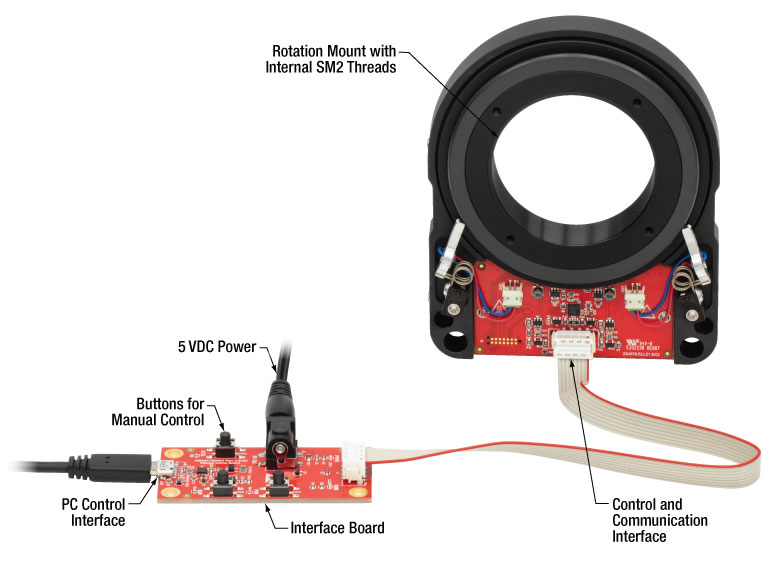
Figure 1.2 The components of the ELL21K Rotation Mount Bundle are shown connected and with key features labeled.
Multiple Elliptec devices can be controlled using the ELLB Bus Distributor or by splicing multiple connectors onto one ribbon cable. A single bus distributor can connect up to four Elliptec devices; up to 16 devices can be connected if the buses are daisy chained. This bus can be controlled one of three ways: through an interface board (included with the bundles below) to connect to a PC running the Elliptec software, by connecting to an Arduino®2 or Raspberry Pi®3 board, or by wiring the connector pins to a user-supplied control board. Alternatively, up to 16 devices can be spliced onto a single ribbon cord. The devices can then be simultaneously controlled by the interface board or selectively controlled by the Elliptec software. See the manual for instruction on how to splice multiple devices onto a ribbon cord and the Pin Diagrams tab for pin assignments when making custom connections.
- Picoflex is a registered trademark of Molex Incorporated.
- Arduino is a registered trademark of Arduino Sa Société Anonym (SA).
- Raspberry Pi is a registered trademark of the Raspberry Pi Foundation.
| Elliptec Resonant Motor Products | |||||||
|---|---|---|---|---|---|---|---|
 |
 |
 |
 |
 |
 |
 |
 |
| Multi-Position Sliders |
28 mm Linear Stage |
60 mm Linear Stage |
Rotation Stage |
Ø1/2" Rotation Mount |
Ø1" Rotation Mount |
Ø2" Rotation Mount |
Motorized Iris |
| Specificationsa | |
|---|---|
| Performance | |
| Travel | 360° Continuousb |
| Maximum Speedc | 260°/s |
| Bidirectional Repeatabilityd | 0.05° (0.87 mrad) |
| Bidirectional Accuracye | 0.035° (0.61 mrad) |
| Backlash | 0.018° (0.31 mrad) |
| Encoder Resolution (Absolute Magnetic Encoder) |
65536 counts/rev |
| Minimum Incremental Motion | 0.0055° (96 µrad) |
| Minimum Holding Torque (Both Motors Engaged) |
6.3 cN•m |
| Axis Wobblef | 0.032° (0.56 mrad) |
| Maximum Total Loadg | Vertical: 100 g (3.5 oz) Horizontal: 300 g (10.6 oz) |
| Minimum Lifetimeh | >403 000 Revolutions (100 km) |
| Electrical | |
| Motor Type | Elliptec® Resonant Piezo |
| DC Voltage Input | 4.5 to 5.5 V |
| Typical Current Consumption, During Movement |
800 mA |
| Typical Current Consumption, During Standby |
50 mA |
| Communications | |
| Bus | Multi-Drop 3.3 V/5 V TTL RS232 |
| Connector on Rotation Stage Board | Picoflex® |
| Connectors on Interface Board | Picoflex®, Micro USB, DC Jack [6.3 mm OD (GND), 2.1 mm ID (+5 V)] |
| Speed | 9600 baud |
| Data Length (1 Stop Bit, No Parity) | 8 bit |
| Protocol Data Format | ASCII HEX |
| Module Address and Command Format | Mnemonic Character |
| Mechanical | |
| Mounting Thread | SM2 (2.035"-40) |
| Dimensions of the Rotation Mount Board | 92.0 x 115.0 x 21.0 mm (3.62" x 4.53" x 0.83") |
| Weight of Rotation Mount Board | 260 g (9.2 oz) |
| Environmental Operating Conditions | |
| Temperature Range | 15 to 40 °C (59 to 104 °F) |
| Maximum Relative Humidity (Non-Condensing) |
<80% at 31 °C |

Click to Enlarge
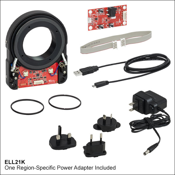
Figure 2.1 Components of the ELL21K Bundle
(One Region-Specific Power Adapter Included with the Power Supply)
Click to Enlarge
Figure 2.2 Mechanical Drawing of the Rotation Mount
For more information on mounting options see the Operation tab.
Click to Enlarge
Figure 2.3 Mechanical Drawing of the Interface Board
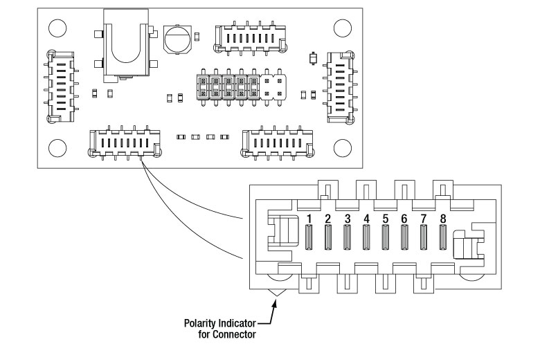
| Connector J1 Pinouta | ||
|---|---|---|
| Pin | Type | Function |
| 1 | PWR | Ground |
| 2 | OUT | ODTX - Open Drain, Transmit 3.3 V TTL RS232 |
| 3 | IN | RX Receive - 3.3 V TTL RS232 |
| 4 | OUT | In Motion, Open Drain, Active Low, Max 5 mA |
| 5 | IN | JOG/Mode, Active Low, Max 5 V |
| 6 | IN | BW Backward, Active Low, Max 5 V |
| 7 | IN | FW Forward, Active Low, Max 5 V |
| 8 | PWR | VCC +5 V ±10%; 800 mA |

Click to Enlarge
Figure 3.1 Pinout diagram of the Picoflex® connector is shown referended to a partial diagram
of the ELL21 Rotation Mount Board.
| ELLB Connector J1, J2, J3, and J4 Pinouta,b | ||
|---|---|---|
| Pin | Type | Function |
| 1 | PWR | Ground |
| 2 | OUT | ODTX - Open Drain, Transmit 3.3 V TTL RS232 |
| 3 | IN | RX Receive 3.3 V TTL RS232 |
| 4 | OUT | In Motion, Open Drain, Active Low, Max 5 mA |
| 5 | IN | Not Connected |
| 6 | IN | Not Connected |
| 7 | IN | Not Connected |
| 8 | PWR | VCC +5 V ± 10%; 800 mA per Connected Device |
Click to Enlarge
Figure 3.2 Pinout diagram of the Picoflex® connector is shown referenced to a simplified diagram
of the ELLB Bus Distributor. The polarity indicator on the connector
must be adjacent to the red wire on the supplied 8-connector cables.
Operation Notes
This tab contains information on handling, mounting, and operating the ELL21K(/M) Rotation Mount Bundle.
Contents- Handling
- Mounting and Loading the Rotation Mount
- Supplying Power
- Operation of the Motors
- Positioning the Rotation Mount
- Resonance Frequencies
Click to Enlarge
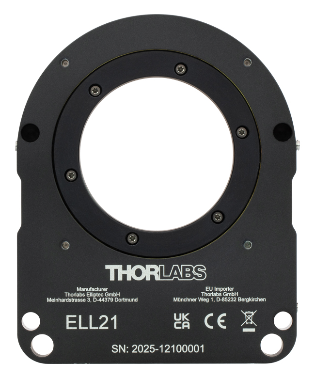
Figure 4.2 The Rotation Mount, Back
Click to Enlarge
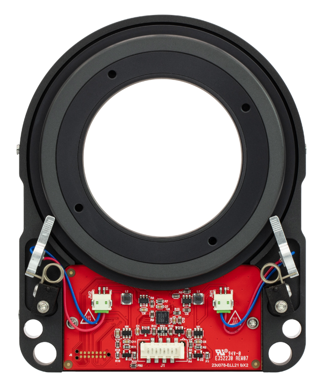
Figure 4.1 The Rotation Mount, Front
Handling
The rotation mount and interface board included in the ELL21K(/M) bundle are robust to general handling. To ensure reliable operation, keep the surface of the plastic track contacted by the motors free of oils, dirt, and dust. It is not necessary to wear gloves while handling the rotation mount, but avoid touching the track to keep it free of oils from fingerprints. If it is necessary to clean the track, it may be wiped with isopropyl alcohol or mineral spirits (white spirit). Do not use acetone, as this solvent will damage the plastic track.
ESD precautions should be taken, as an electrostatic discharge can produce an electrical signal that may cause an unintended movement of the mount. Limit the strength of magnetic fields in proximity to the magnetic sensor to ±5 mT to avoid negatively affecting positioning operations.
Mounting and Loading the Rotation Mount
The rotation mount may be mounted either vertically or horizontally. The Elliptec motors should be facing up if the mount is used horizontally. The mount has several mounting features that can be used with Thorlabs components or within a custom OEM assembly. Four 4-40 threaded holes on the back of the mount are spaced 60 mm apart for compatibility with our 60 mm cage system. Each mount also features an 8-32 (M4 x 0.7) tap for post mounting and 1/4" bores for horizontal mounting on a table surface. There are also two Ø6 mm through holes for ER rods and close proximity mounting of two devices. Two additional 6.5 mm deep blind holes for ER05 cage rods ensure alignment of mounts in close proximity.
Click for Details
Figure 4.3 The rotation mount can be mounted in a 60 mm cage system using the 4-40 threaded holes on the back.

Click for Details
Figure 4.4 The rotation mount can be post-mounted and ER cage rods holes allow two mounts to be aligned in close proximity.
Click to Enlarge
Figure 4.5 Features of the Rotation Mount
The maximum allowed weight of the mounted optic is 100 g when mounted vertically and 300 g when mounted horizontally. The load must be centered on the mount in order to achieve these values. In all cases of mounting and loading, ensure that nothing interferes with the moving parts of the rotation mount and that the mount and its load are securely fastened to prevent jostling during movement. Jostling of the stage or the load can cause an encoder error.
Supplying Power
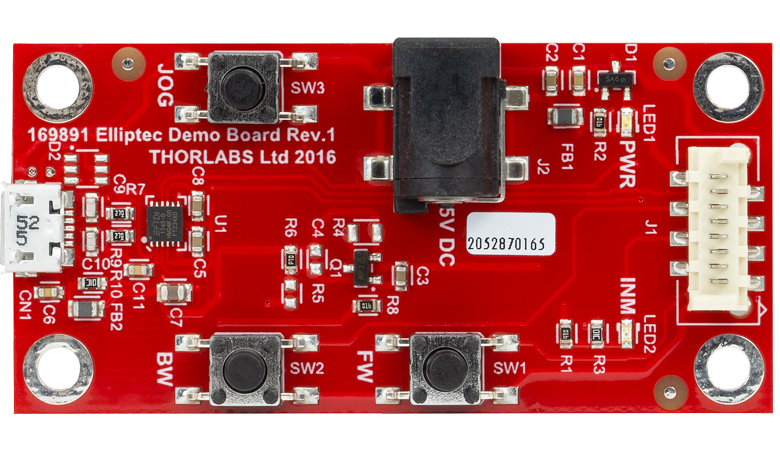
When the setup includes the interface board, power may be supplied through the Micro-B USB connector and/or the 5 VDC power socket located on the board. The electronics on the interface board convert the applied DC signal to a sinusoidal signal oscillating at the required resonance frequency.
The ELL21K(/M) bundle includes a 5 VDC power supply whose connector mates with the power socket on the interface board. Delivering power through this socket also allows the Micro-B USB connector to be used for a computer to control the mount remotely. The power supplied by a computer through the USB 2.0 connection is not sufficient to power the mount. If computer control is not necessary, another option for supplying power to the mount is a CPS1 portable USB 5 V battery pack connected to the Micro-B USB connector on the interface board.
When the implementation does not include the interface board, the connection with the power source is made using the pins on the Picoflex® connector that is included on the rotation mount board. A pinout diagram of this connector is included in the Pin Diagram tab, and information on powering and addressing the rotation mount is given in the manual and the communications protocol manual, respectively.
Click to Enlarge
Figure 4.6 The Interface Board
Click to Enlarge
Figure 4.7 Features of the Interface Board
Operation of the Motors
The motion of the rotation mount is controlled by forcing the piezoelectric elements to vibrate at specific ultrasonic frequencies. For each motor, there is one ultrasonic resonant frequency that will push the mount forward, and another that will pull the mount backward. Operating a motor at one of its resonance frequencies causes the tip of the motor to continuously cycle in a tight clockwise elliptical path. When the motor is driven at its other resonant frequency, the tip of the motor cycles through that same path in a counterclockwise direction. Both resonant frequencies are around 100 kHz. The total displacement at the tip of motor is a function of the mechanical load it is driving and the voltage supplied to the piezo element. In the case of no loading and a 5 V maximum driving voltage at a resonant frequency, the tip of the motor expands and contracts no more than a few microns while tracing the elliptical path. Please see The Elliptec® Motor tab for more information and an animation illustrating the operational principle of the motors.
Positioning the Rotation Mount
Note that the rotation mount is not intended for continuous operation. We recommend operation with duty cycles of less than 40% during general use, while operation with duty cycles greater than 60% should be limited to a few seconds.
The movement of the mount may be controlled through computer control via the Elliptec® software package that may be downloaded, or by sending simple signals to digital lines on the mount's board. A link to download the software and accompanying documentation can be found in the Software tab.
Multiple Elliptec devices can be controlled using the ELLB Bus Distributor or by splicing multiple connectors onto one ribbon cable. A single bus distributor can connect up to four Elliptec devices; up to 16 devices can be connected if the buses are daisy chained. This bus can be controlled one of three ways: through an interface board (included with the bundles below) to connect to a PC running the Elliptec software, by connecting to an Arduino® or Raspberry Pi® board, or by wiring the connector pins to a user-supplied control board. Note that if an interface board is used, its on-unit buttons will be disabled. Alternatively, up to 16 devices can be spliced onto a single ribbon cord. The devices can then be simultaneously controlled by the interface board or selectively controlled by the Elliptec software. See the manual for instruction on how to splice multiple devices onto a ribbon cord and the Pin Diagrams tab for pin assignments when making custom connections. The communications protocol manual describes how to use the software to individually address each connected device. A link to download the software and accompanying documentation can be found in the Software tab.
The default increment to move the mount forward and backward is 10°, and a custom increment can be set using the Elliptec software or by sending the appropriate ASCII message(s) as specified in the communications protocol manual. The Elliptec software can be used to move the mount to absolute and relative positions, in addition to jogging the mount forward or backward. The software is also used to set the jog step size, read the position of the mount, and adjust the position of Home, as is described in the previous section.
Readings from the magnetic sensor, which can resolve angular increments of 0.0055° (96 µrad), are used to position the mount and when executing the Home command. The travel range of the mount is not limited, but the reported orientation of the mount is always expressed as a value between 0° and 359.99°. The minimum incremental movement of the mount is 0.0055° (96 µrad), and it can be positioned with a repeatability of 0.05° (0.87 mrad) in response to signals from the magnetic sensor.
Resonance Frequencies
On power-up, the factory default setting instructs each motor driving the rotation mount to search for the resonance frequencies that will deliver the best performance. During this process, the rotation mount will translate a forward and backward by a small amount. If movement on start-up is undesirable, it is possible to disable this calibration procedure by using the serial port to initialize the frequencies on power-up. A new search for optimal resonance frequencies may be performed at any time; to maintain optimal performance, it is recommended that new searches be performed after changes in loading and/or ambient temperature. Please see the manual for details.
Click to Enlarge
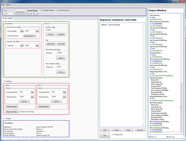
The Elliptec Piezoelectric Resonant Motor Control Software GUI
Software for Devices Driven by Elliptec® Piezoelectric Resonant Motors
All devices based on the Elliptec® resonant piezo motor may be controlled by the Elliptec system software, which features an intuitive graphical user interface (GUI). The source code, in C# format, is included in software bundle available for download, and custom applications can be created in any language. The image at right shows a screen capture of the GUI, and the button that follows links to the download page.
Commands are entered in the Sequencer command / wait order section located at the center-left of the GUI. An example of a sequence of commands that might be sent to the device is "Aho0" to move to the rotation stage at address "A" to the home position in the clockwise direction, and then "Afw" to move the stage at address "A" forward by the jog increment. The command "As1" is used to perform the frequency search that will identify the optimal resonant frequencies, for the current operating conditions, for Motor 1 at adddress "A."
Software
Version 1.6.5 (May 6, 2025)
Includes the Elliptec System Software, with an easy-to-use GUI. Also available for download is the Communications Protocol manual, which details the communication commands for the Elliptec software package.
| Posted Comments: | |
| No Comments Posted |
Rotation Mount and Stage Selection Guide
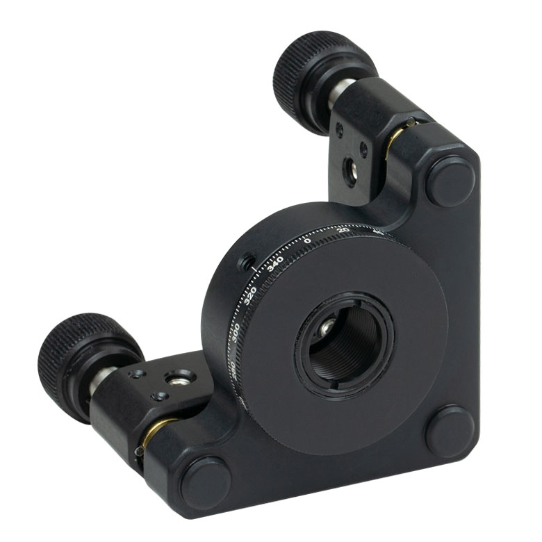
Thorlabs offers a wide variety of manual and motorized rotation mounts and stages. Rotation mounts are designed with an inner bore to mount a Ø1/2", Ø1", or Ø2" optic, while rotation stages are designed with mounting taps to attach a variety of components or systems. Motorized options are powered by a DC Servo motor, 2 phase stepper motor, piezo inertia motor, or an Elliptec™ resonant piezo motor. Each offers 360° of continuous rotation.
Manual Rotation Mounts
| Rotation Mounts for Ø1/2" Optics | |||||||
|---|---|---|---|---|---|---|---|
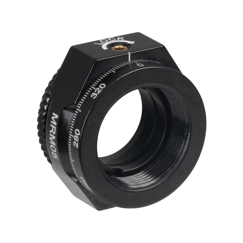
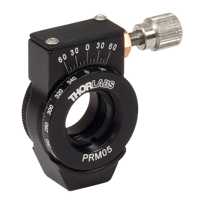
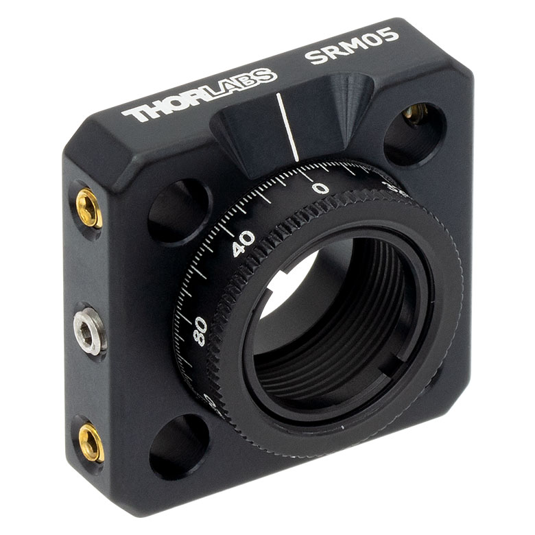
| Item # | MRM05(/M) | RSP05(/M) | CRM05 | PRM05(/M)a | SRM05 | KS05RS | CT104 |
| Click Photo to Enlarge |
 |
 |
 |
 |
 |
 |
 |
| Features | Mini Series | Standard | External SM1 (1.035"-40) Threads |
Micrometer | 16 mm Cage-Compatible | ±4° Kinematic Tip/Tilt Adjustment Plus Rotation | Compatible with 30 mm Cage Translation Stages and 1/4" Translation Stagesb |
| Additional Details | |||||||
| Rotation Mounts for Ø1" Optics | ||||||||
|---|---|---|---|---|---|---|---|---|
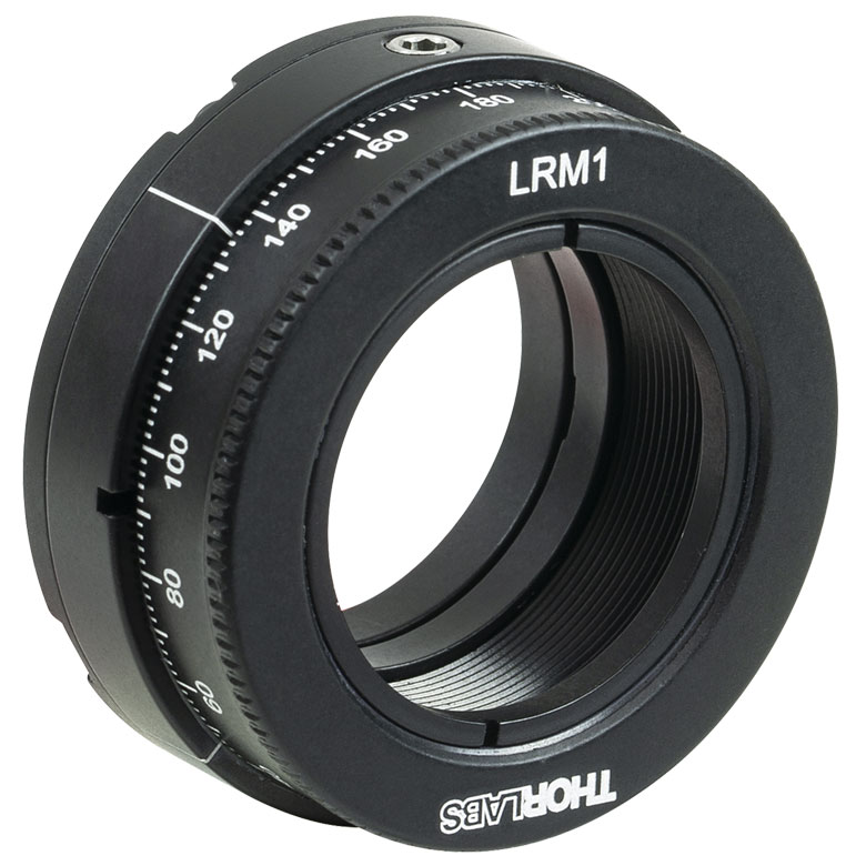
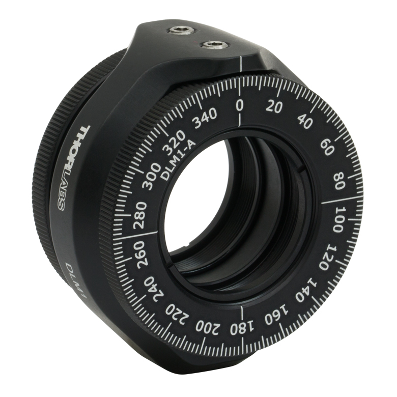
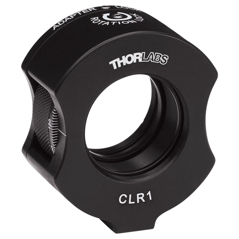
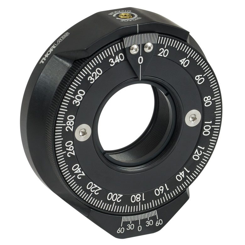
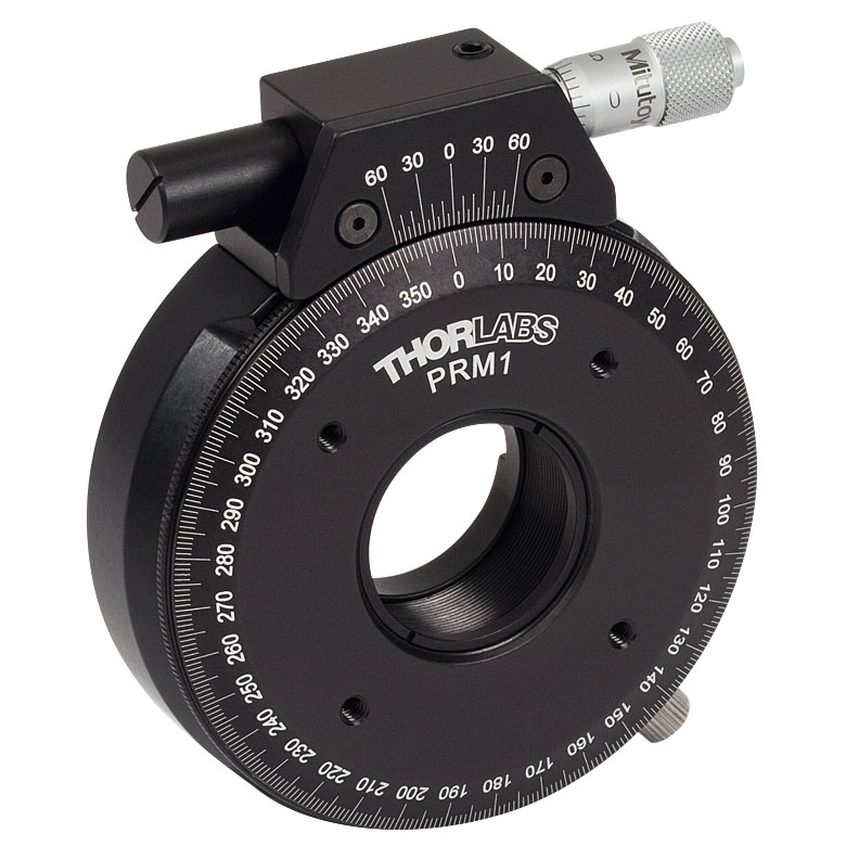
| Item # | RSP1(/M) | LRM1 | RSP1D(/M) | DLM1(/M) | CLR1(/M) | RSP1X15(/M) | RSP1X225(/M) | PRM1(/M)a |
| Click Photo to Enlarge |
 |
 |
 |
 |
 |
 |
|
 |
| Features | Standard | External SM1 (1.035"-40) Threads |
Adjustable Zero | Two Independently Rotating Carriages | Rotates Optic Within Fixed Lens Tube System |
Continuous 360° Rotation or 15° Increments |
Continuous 360° Rotation or 22.5° Increments |
Micrometer |
| Additional Details | ||||||||
| Rotation Mounts for Ø1" Optics | ||||||
|---|---|---|---|---|---|---|
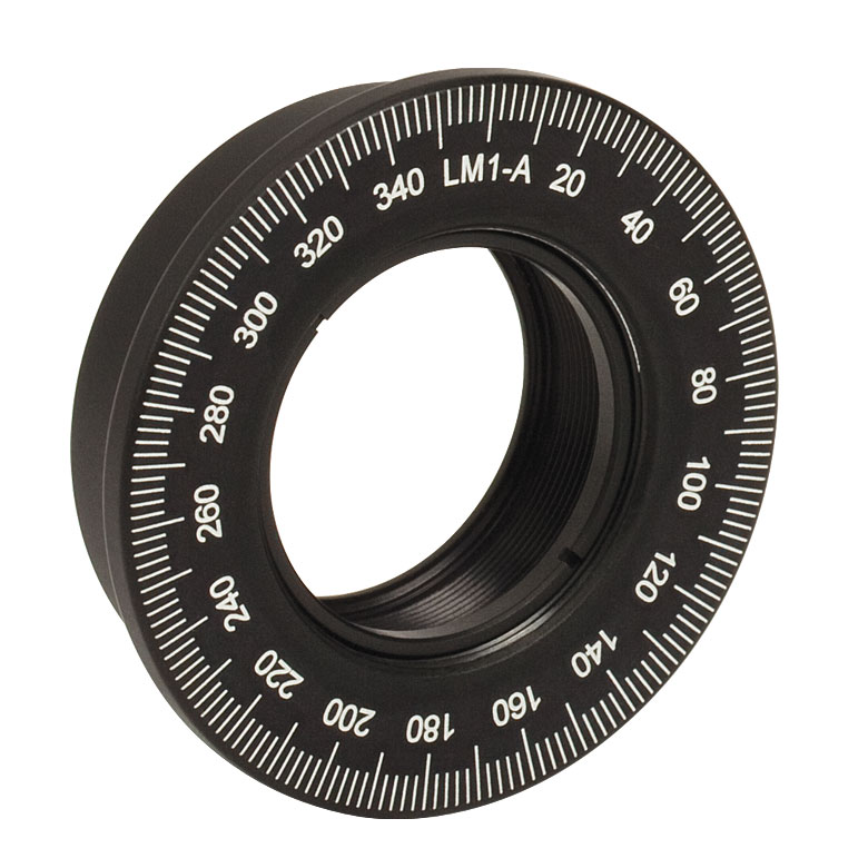
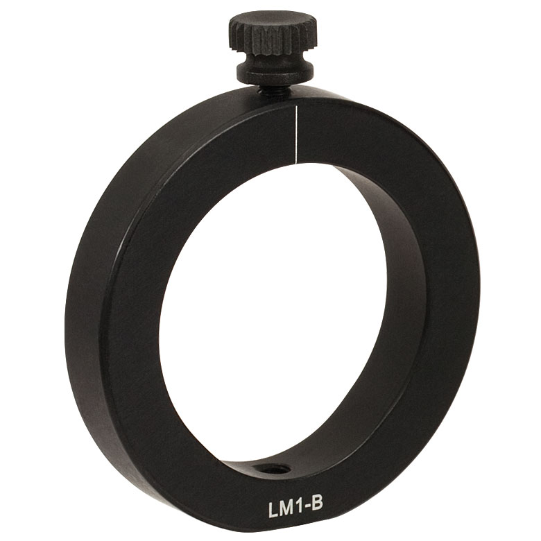
| Item # | LM1-A & LM1-B(/M) |
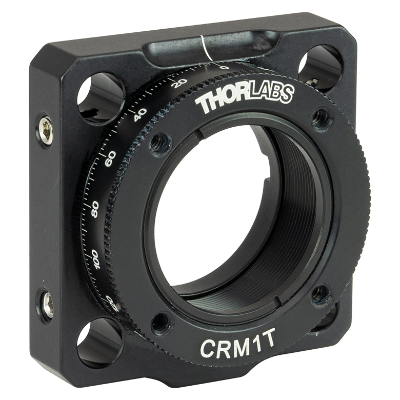
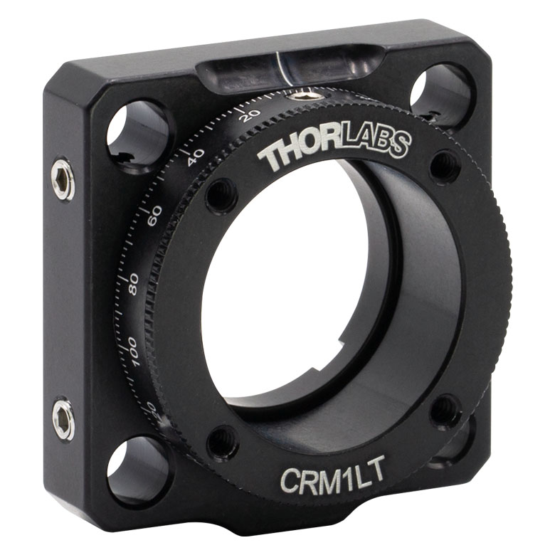
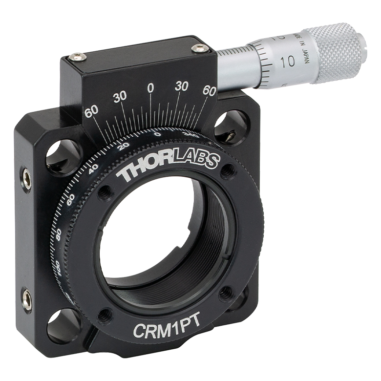
CRM1T(/M) | CRM1LT(/M) | CRM1PT(/M) | KS1RS | K6XS |
| Click Photo to Enlarge |
  |
 |
 |
 |
 |
 |
| Features | Optic Carriage Rotates Within Mounting Ring | 30 mm Cage-Compatiblea | 30 mm Cage-Compatible for Thick Opticsa |
30 mm Cage-Compatible with Micrometera |
±4° Kinematic Tip/Tilt Adjustment Plus Rotation | Six-Axis Kinematic Mounta |
| Additional Details | ||||||
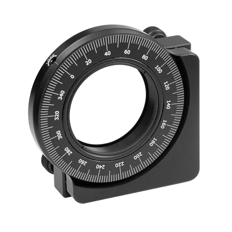
| Rotation Mounts for Ø2" Optics | |||||||
|---|---|---|---|---|---|---|---|
| Item # | RSP2(/M) | RSP2D(/M) | PRM2(/M) | LM2-A & LM2-B(/M) |
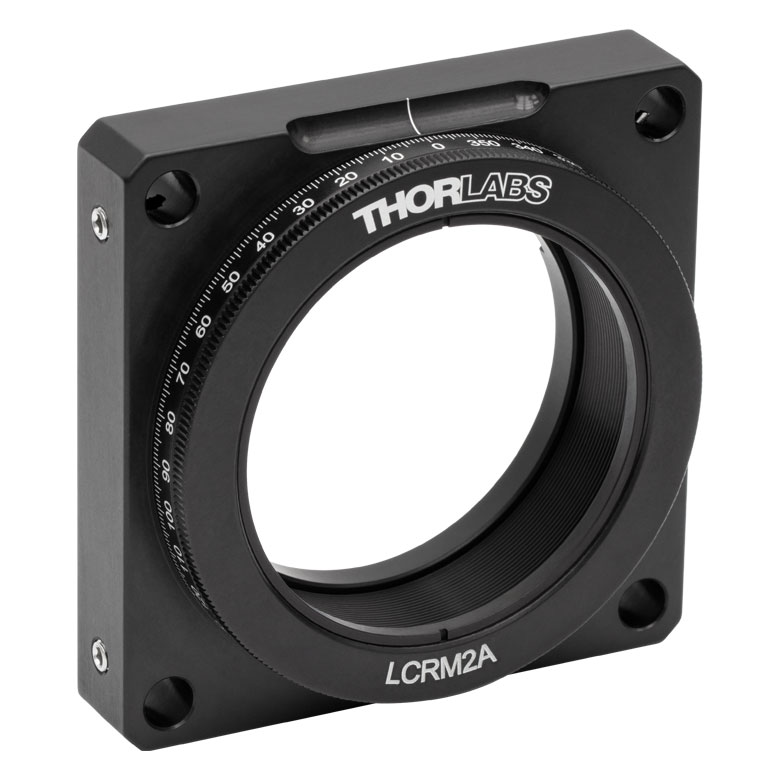
LCRM2A(/M) | KS2RS | K6X2 |
| Click Photo to Enlarge |  |
 |
 |
  |
 |
 |
 |
| Features | Standard | Adjustable Zero |
Micrometer | Optic Carriage Rotates Within Mounting Ring | 60 mm Cage-Compatible | ±4° Kinematic Tip/Tilt Adjustment Plus Rotation | Six-Axis Kinematic Mount |
| Additional Details | |||||||
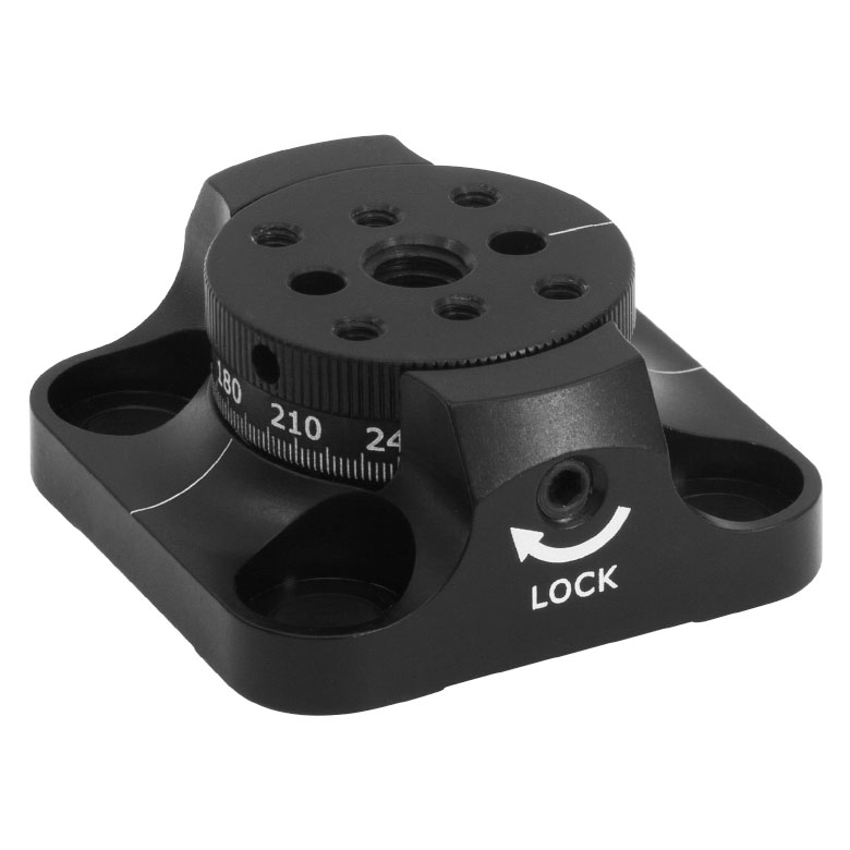
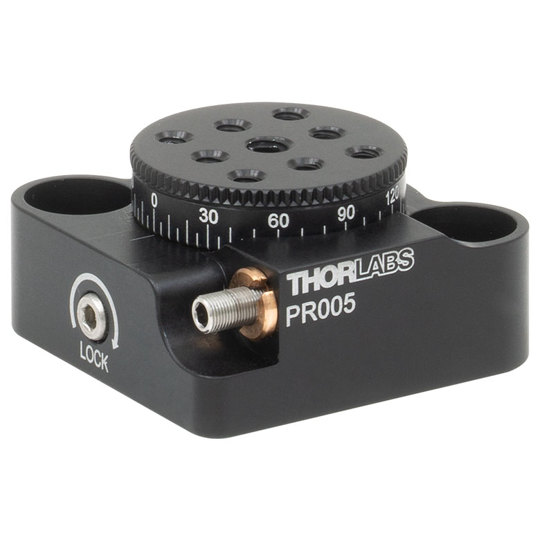
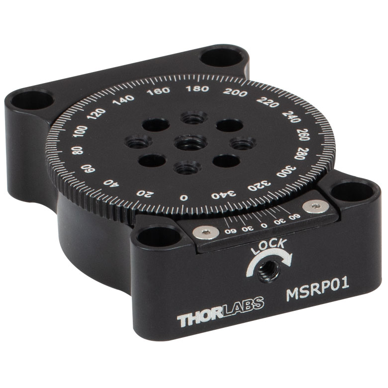
Manual Rotation Stages
| Manual Rotation Stages | ||||||
|---|---|---|---|---|---|---|
| Item # | RP005(/M) | PR005(/M) | MSRP01(/M) | RP01(/M) | RP03(/M) | QRP02(/M) |
| Click Photo to Enlarge |
 |
 |
 |
 |
 |
 |
| Features | Standard | Two Hard Stops | ||||
| Additional Details | ||||||
| Manual Rotation Stages | ||||||
|---|---|---|---|---|---|---|
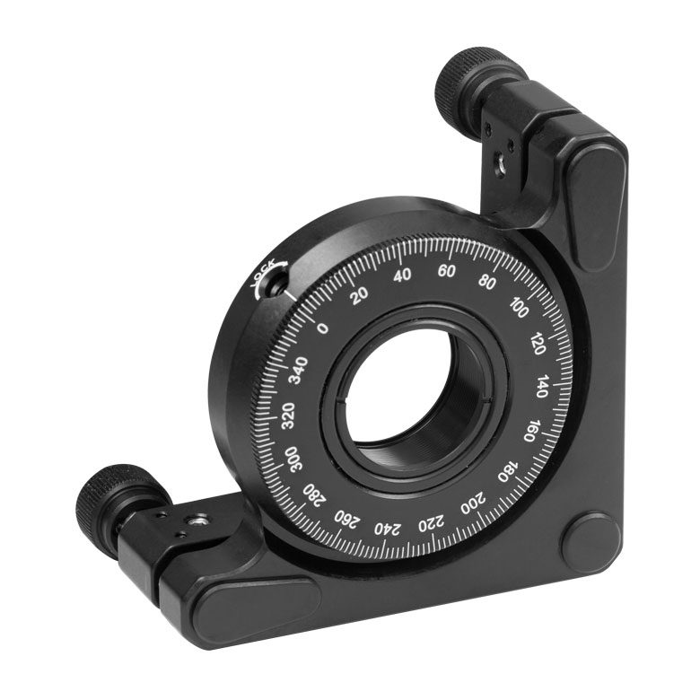
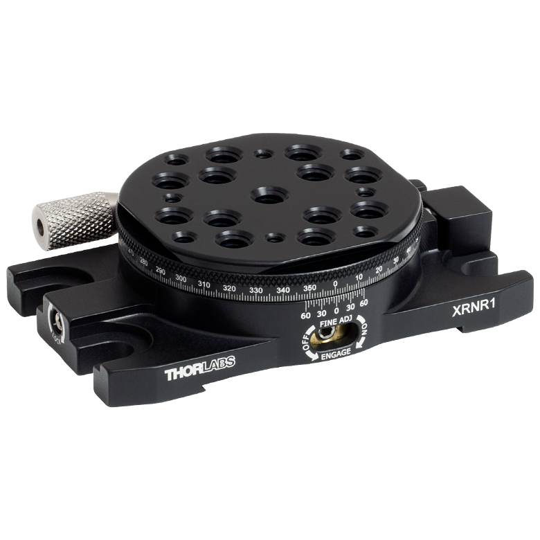
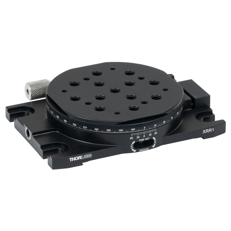
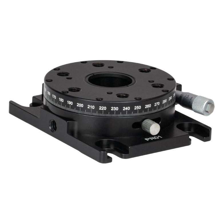
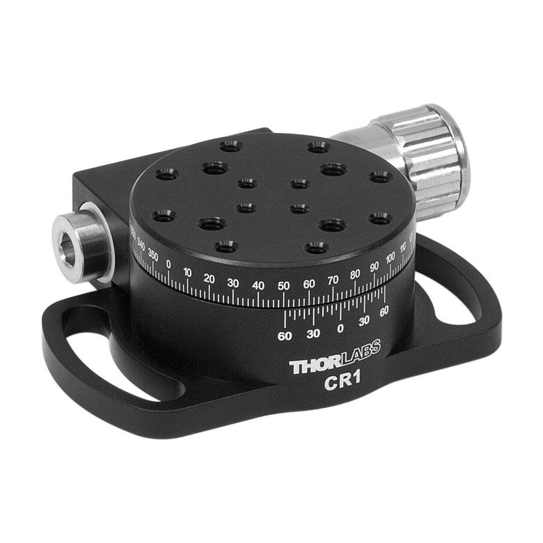
| Item # | XRNR1(/M) | XRR1(/M) | PR01(/M) | CR1(/M) | XYR1(/M) | OCT-XYR1(/M) |
| Click Photo to Enlarge |
 |
 |
 |
 |
 |
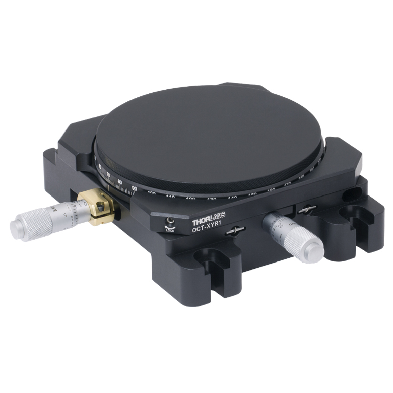 |
| Features | Fine Rotation Adjuster and 2" Wide Dovetail Quick Connect |
Fine Rotation Adjuster and 3" Wide Dovetail Quick Connect |
Fine Rotation Adjuster and SM1-Threaded Central Aperture |
Fine Pitch Worm Gear | Rotation and 1/2" Linear XY Translation | |
| Additional Details | ||||||
Motorized Rotation Mounts and Stages
| Motorized Rotation Mounts and Stages with Central Clear Apertures | |||||
|---|---|---|---|---|---|
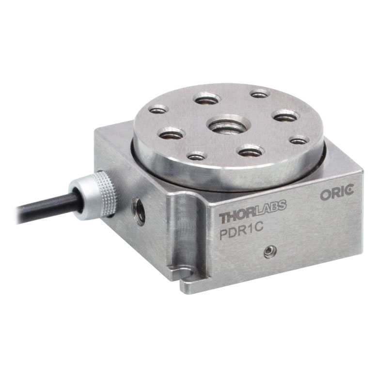
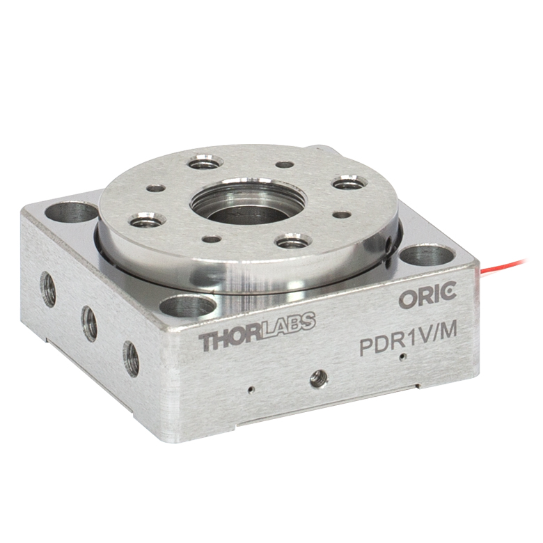
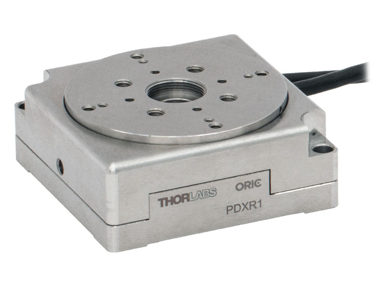
| Item # | DDR25(/M) | PDR1C(/M) | PDR1(/M) | PDR1V(/M) | PDXR1(/M) |
| Click Photo to Enlarge |
 |
 |
 |
 |
 |
| Features | Compatible with SM05 Lens Tubes, 16 mm Cage System, & 30 mm Cage System |
Compatible with 16 mm Cage System |
Compatible with SM05 Lens Tubes & 30 mm Cage System |
Vacuum-Compatible; Also Compatible with SM05 Lens Tubes & 30 mm Cage System |
Compatible with SM05 Lens Tubes & 30 mm Cage System |
| Additional Details | |||||
| Motorized Rotation Mounts and Stages with Central Clear Apertures | |||||||
|---|---|---|---|---|---|---|---|
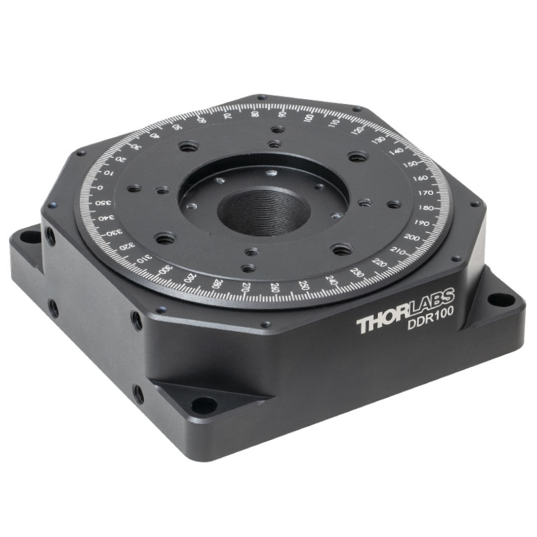
| Item # | K10CR1(/M) | PRM1Z8(/M)a | DDR100(/M) | ELL16 | ELL14 | ELL21(/M) | HDR50(/M) |
| Click Photo to Enlarge |
 |
 |
 |
 |
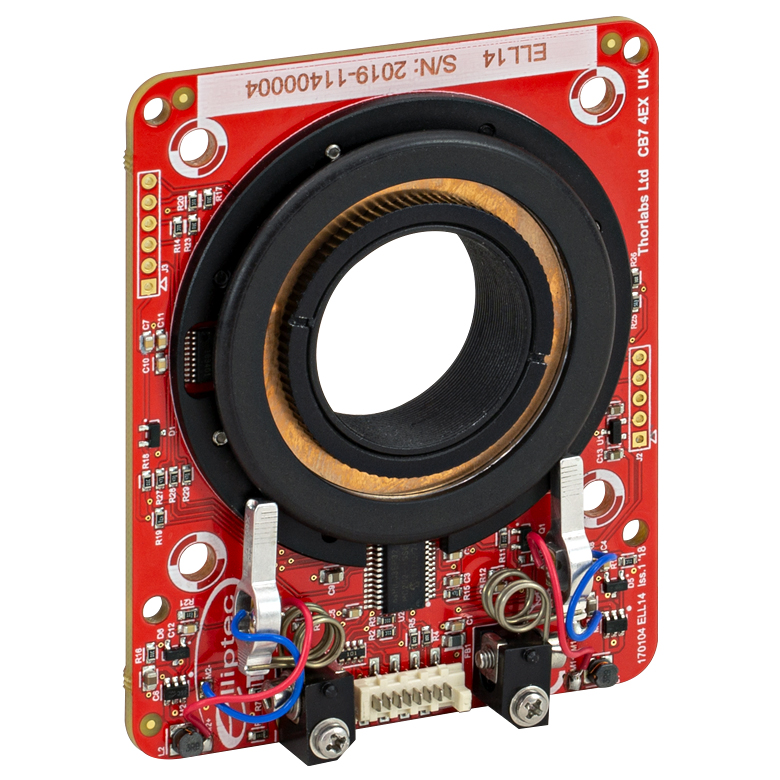 |
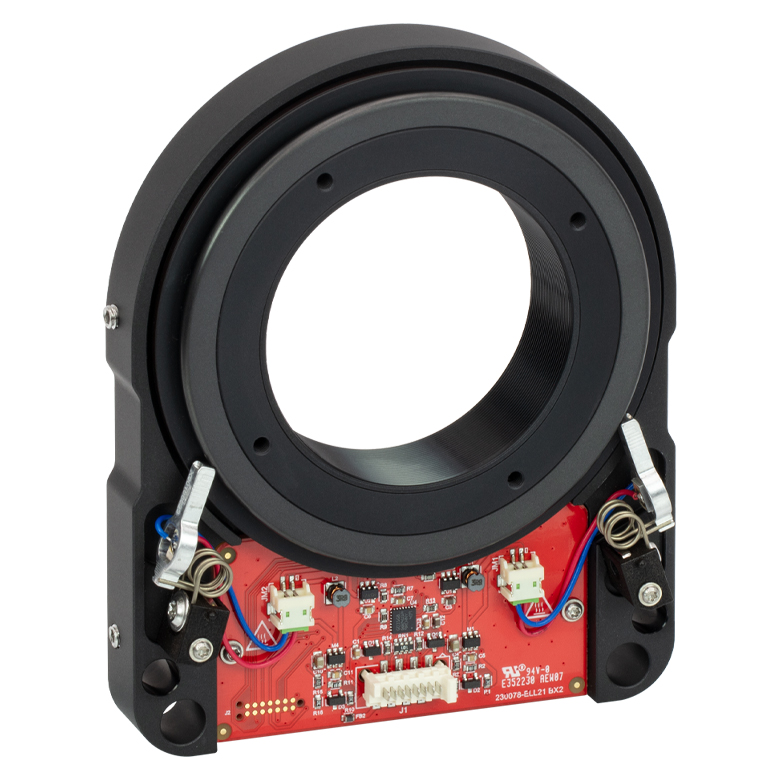 |
 |
| Features | Compatible with SM1 Lens Tubes & 30 mm Cage System | Compatible with SM1 Lens Tubes, 16 mm Cage System, 30 mm Cage System |
Compatible with SM05 Lens Tubes, Open Frame Design for OEM Applications |
Compatible with SM1 Lens Tubes, Open Frame Design for OEM Applications |
Compatible with SM2 Lens Tubes, Open Frame Design for OEM Applications |
Compatible with SM2 Lens Tubes |
|
| Additional Details | |||||||
| Motorized Rotation Mounts and Stages with Tapped Platforms | ||
|---|---|---|
| Item # | PRMTZ8(/M)a | ELL18(/M)b |
| Click Photo to Enlarge |
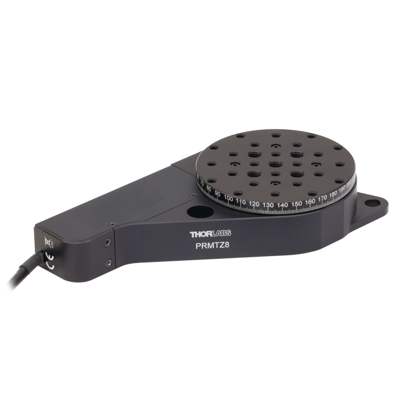 |
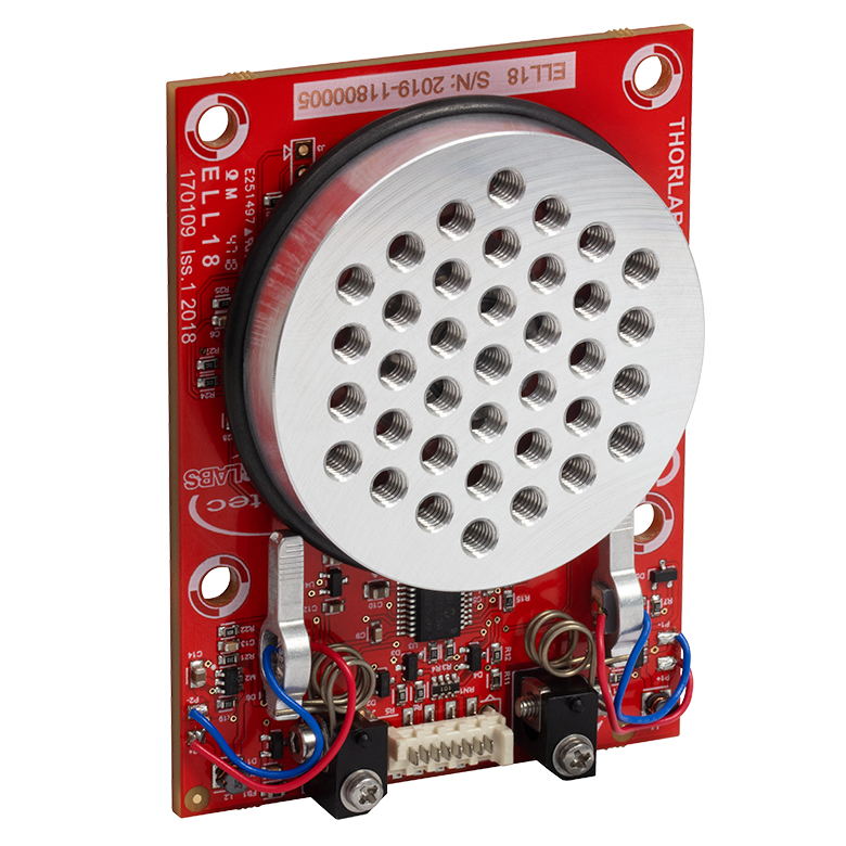 |
| Features | Tapped Mounting Platform for Mounting Prisms or Other Optics | Tapped Mounting Platform, Open Frame Design for OEM Applications |
| Additional Details | ||

 Zoom
Zoom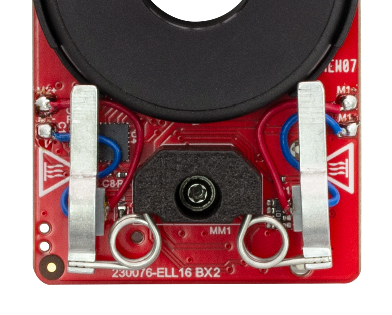
Click to Enlarge
Figure G1.1 The motors' aluminum tips contact the black plastic track encircling the rotation mount. This track should not be touched to prevent debris and oil building up on the track.
- Ideal for OEM Evaluation Testing
- Easily Integrate into a Setup
- Operate using Manual and/or Computer Control
- Included Power Supply is Required for Powering the Mount
The Rotation Mount Bundle is a complete package that includes the ELL21(/M) rotation mount. The ELL21K(/M) package facilitates quick integration of the rotation mount into laboratory setups and other experimental applications. It also provides a convenient means to evaluate incorporating this technology into OEM applications.
The tips of both motor housings are in firm contact with the plastic track encircling the rotation mount, as can be seen in Figure G1.1. The motors are installed with opposite orientations and clockwise (and counterclockwise) rotation occurs when one motor pushes the track forward while the other pulls it backward.
| Included in the ELL21K(/M) Bundle | |
|---|---|
| ELL21(/M) Rotation Mount | 5 V Power Supply with Region-Specific Power Adapter |
| Interface Board | 8-Conductor 28 AWG Ribbon Cable |
| Micro-B USB Cable | PC-Based Software for Download |

 Zoom
ZoomClick to Enlarge
Figure G2.1 Features of the ELL21(/M) Rotation mount
The ELL21(/M) Rotation Mount is offered to meet the needs of applications whose designs require multiple networked Elliptec® resonant motor products. It possesses an SM2-threaded bore for mounting Ø2" optics. Details describing the dimensions, including the spacing of mounting holes, and other specifications of the mount are given in the Specs tab. Please contact us to discuss customizing the rotation mount.
The PCB of the rotation mount incorporates a male 8-pin Picoflex® connector (header). Each ELL21(/M) mount ships with the female 8-pin Picoflex® connector (receptacle) that mates with the connector (header) on the board.

 Zoom
Zoom
- Adapters Attach Using M3 Counterbores
- ELLA6(/M) Adapter Features:
- 3 mm Keyway for Fiber Alignment Accessories
- 4-40 Mounting Holes for 30 mm Cage System
- 1/4"-20 (M6 x 1.0), 6-32 (M3 x 0.5), 4-40 (M3 x 0.5) Taps
- ELLA7(/M) Adapter Features:
- SM1 (1.035"-40) Thread for Ø1" Lens Tubes and Mounted Optics
- 4-40 Mounting Holes for 30 mm Cage System
- 1/4"-20 (M6 x 1.0) and 6-32 (M3 x 0.5) Taps
- ELLA8 Adapter Features Five SM05 (0.535"-40) Threaded Bores for Ø1/2" Lens Tubes or Mounted Optics
These adapter plates provide additional mounting features for the ELL21(/M) Rotation Mount. The plates mount to the moving world using four included (M3 x 0.5) screws. Note that imperial and metric adapters are compatible with either type of stage. All three adapters are also compatible with our HDR50(/M) rotation stage and the ELLA6(/M) and ELLA7(/M) adapters are also compatible with the PRM1(/M)Z8 rotation stage.
The ELL6(/M) adapter features an array of mounting holes for compatibility with stages and mounts including the GN05(/M) small goniometric stage, MS series 1/4" travel stages, T12 series 1/2" travel stages, and BSH series cube and prism mounts.

Click for Details
Figure G3.4 ELLA8 5-Position SM05-Threaded Adapter Plate

 Zoom
Zoom| Specifications | ||
|---|---|---|
| Item # | ELLC2 | |
| DC Voltage Input to Controller | 4.5 to 5.5 V | |
| Typical Current Consumption Per Module |
Movement | 800 mA |
| Standby | 50 mA | |
| Operating Temperature Range | 15 to 40 °C | |
| Ribbon Cable Length (1 Included) | 250 mm (9.8") | |
| Dimensions (Interface Board Only) | 66.0 mm x 32.0 mm x 12.5 mm (2.60" x 1.26" x 0.49") |
|
| Weight (Interface Board Only) | 10.8 g (0.022 lbs) | |
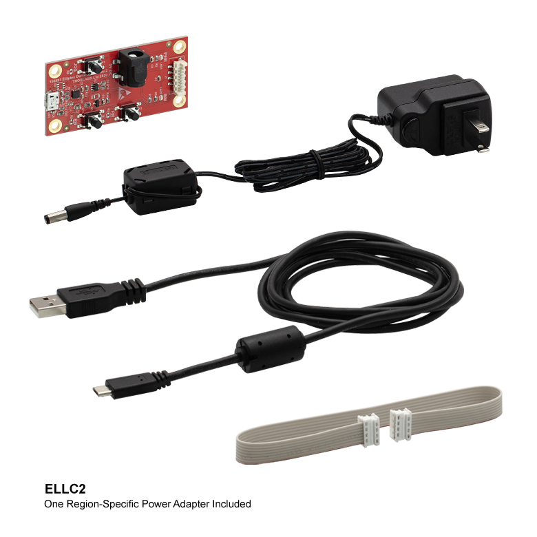
- Convert Any Single ELL Device into a Kit by Adding the Following:
- Interface Board
- USB Micro-B Cable
- Picoflex®1 Cable
- 5 V Power Supply with Regional Adapter (US, UK, AU, or EU)
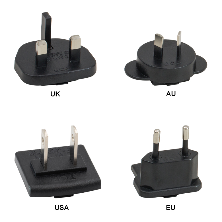
Click for Details
Figure 749A Region-Specific Adapters for the ELLC2 Power Adapter
Thorlabs' ELLC2 Accessory Upgrade Pack is designed to include all of the items necessary to convert any single ELL slider, stage, or mount into an ELL kit2. The included interface board features three buttons to control the position of a connected ELL stage and the USB port enables direct connection to a PC via the included USB Micro-B cable. A 0.25 m Picoflex® cable with 8 loaded circuits that connects the interface board to the ELL device and a 5 V power supply with a regional adapter (US, UK, AU, or EU) are also included with the kit.
1. Picoflex® is a registered trandemark of Molex Incorporated.
2. Mounting brackets for the ELL17(/M), ELL18(/M), and ELL20(/M) can be ordered by contacting Tech Support.
| Included in the ELLC2 Accessory Upgrade Kit | |
|---|---|
| USB 2.0 Micro-B Cable, 1.5 m Long | 5 V Power Supply with Region-Specific Power Adapter, 1.5 m Long |
| Interface Board | 8-Conductor 28 AWG Ribbon Cable, 250 mm Long |

 Zoom
Zoom| Specifications | ||
|---|---|---|
| Item # | ELLB | |
| Voltage Rating | 4.5 to 5.5 V | |
| Typical Current Consumption Per Module | Movement | 800 mA |
| Standby | 50 mA | |
| Maximum Board Current | 4.0 A | |
| Operating Temperature Range | 15 to 40 °C | |
| Ribbon Cable Length (4 Included) | 250 mm | |
| Maximum Supported Ribbon Cable Length |
500 mm | |
| Dimensions | 65.0 mm x 32.0 mm x 12.5 mm (2.56" x 1.26" x 0.49") |
|
| Weight | 11 g (0.02 lbs) | |
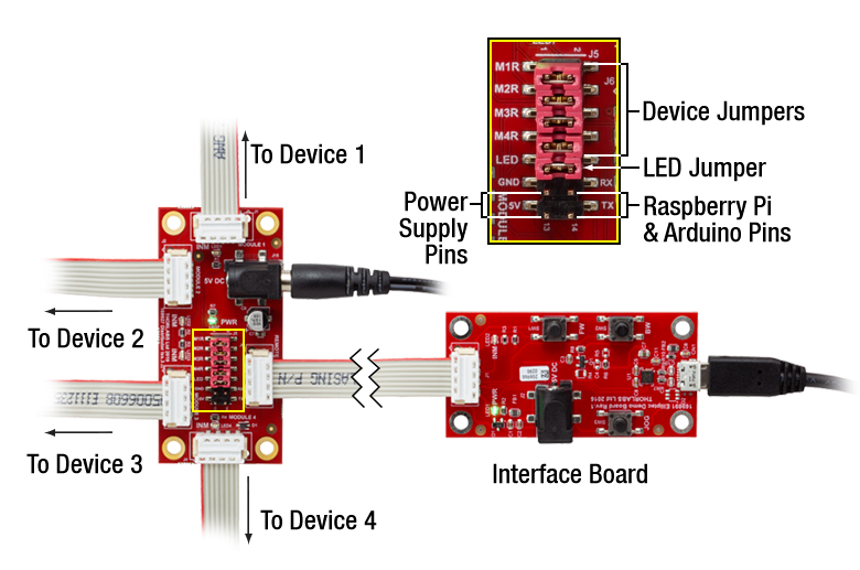
Click to Enlarge
Figure 683A A single bus distributor can be used to control up to four Elliptec devices. The bus can be connected to a PC using the interface board provided with the bundles sold above. Note that the bus is then controlled by the Elliptec software and that the buttons on the interface board are disabled.
- Control and Power up to Four Elliptec® Devices with One Bus
- Daisy Chain Bus Boards to Control up to 16 Elliptec Devices
- Controlled Remotely Using Elliptec System Software (See Software Tab Above)
- Connect to PC Using USB Interface Board Included with Elliptec Bundles
- Five Jumpers and Four 8-Conductor 28 AWG Ribbon Cables Included
- Compatible with Raspberry Pi® and Arduino® Boards
The ELLB Bus Distributor connects up to four Elliptec® devices. Connected devices can be controlled with or without the interface board included with the above bundles. When using the interface board, each connected device is controlled remotely by a PC running the Elliptec software package. The interface board connects to the bus's input port labeled REMOTE; once connected, the interface board's buttons are disabled. For control without using the interface board, see the Pin Diagrams tab for custom connections.
Multiple ELLB Bus Distributors can be daisy chained to control and power up to 16 Elliptec devices; simply connect one of the four MODULE outputs to the second board's REMOTE input. Indicator LEDs are provided to show which device is active. The communications protocol manual describes how to use the software to individually address each connected device. A link to download the software and accompanying documentation can be found in the Software tab.
The bus includes a Ø6.3 mm power connector that supports a 5 V supply with a maximum current of 4 A. As more devices are connected, simultaneous control of the units will require more current to be provided by the power supply; please see the Specs tab for the amount of current drawn by each Ellitpec device. A 5 V, 1 A power supply is included with the above ELL9 and ELL12 bundles. Depending on the current draw of the Elliptec devices connected, this supply provides enough current to power two devices simultaneously.
Fourteen control pins, detailed in Figure 683A, are included for additional functionality. Four pairs of pins are each shorted with a jumper that, when in place, enables the Elliptec software to receive feedback from connected Elliptec devices. The pair of pins labeled LED is shorted with a jumper that, when removed, will disable the indicator LEDs. The 5V and GND allow an optional, user-provided 5 V, 2 A power supply to be used in place of a source connected to the Ø6.3 mm power connector. The RX and TX pins can be used to control the bus with a Raspberry Pi® or Arduino® board, respectively, instead of the Elliptec interface board.
The board is mounted using the Ø3.5 mm through holes provided in each corner. Four 8-conductor, 28 AWG ribbon cables are included.
| Compatible Elliptec Devices | |||||
|---|---|---|---|---|---|
 |
 |
 |
 |
 |
 |
| Multi-Position Sliders | 28 mm Linear Stage | 60 mm Linear Stage | Rotation Stage | Rotation Mount | Motorized Iris |