 Products Home / Optomechanical Components / Optomechanical Mounts / Rotation Mounts / Stepper Motor Rotation Mount
 Stepper Motor Rotation Mount

- Integrated Controller
- Continuous 360° Rotation
- Rotates Optic Within a 30 mm Cage System
- Maximum Speed of 10 Degrees/s
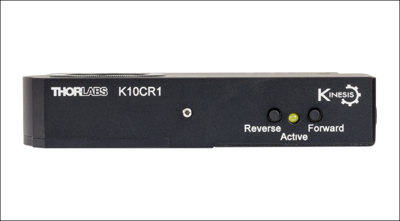
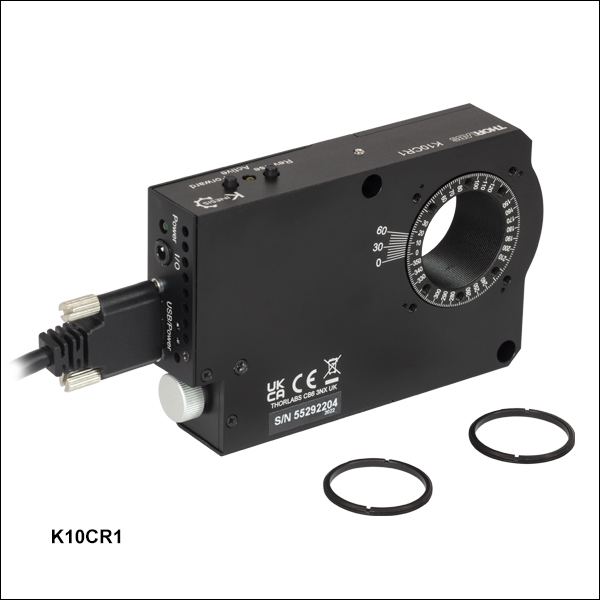
K10CR1
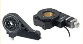
The 30 mm Cage System Rods are Attached to the Fixed Housing while the SM1 Lens Tube Rotates
Application Idea
Thumbscrew for Manual Rotation Adjustment


Please Wait
| Key Specificationsa | |
|---|---|
| Travel Range | 360° Continuousb |
| Maximum Speed | 10 Degrees/s |
| Minimum Speed | 0.005 Degrees/s |
| Maximum Accelerationc | 20 Degrees/s2 |
| Unidirectional Repeatabilityd | ±60 µrad |
| Backlash | ±200 µrad |
| Maximum Load Capacitye | 22 N |
| Repeatable Incremental Movement (Min)f | 0.03° |
| Absolute Accuracyd | ±0.14° |
| Home Location Accuracy | ±100 µrad |
| Dimensions (L x W x H) | 107 mm x 66.0 mm x 21.5 mm (4.21" x 2.60" x 0.84") |
| Weight | 0.22 kg (0.48 lbs) |

Click to Enlarge
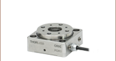
The K10CR1 can be mounted horizontally using adapters sold separately (see below for details).

Click to Enlarge
Two precision Ø6 mm bores allow our Cage Rods to be used to align multiple mounts along the same axis. Once in position, a side-located set screw on each hole secures the stage to the rod.
Features
- Rotates Optics and SM1 (1.035"-40) Lens Tubes within a 30 mm Cage System
- Full 360° Bidirectional Rotation
- Vernier Scale with 12 Arcminute Graduations
- Unidirectional Repeatability of ±60 µrad
- Built-In Controller Powered using USB 2.0 or USB 3.0 Connection
- Input/Output Port for Control via TTL Signals
- No External Controller Required
- Several Adapters Available:
- Table Mounting Plate
- Rotating Platform Adapter
- 60 mm Cage System Adapter
Thorlabs' K10CR1(/M) Rotation Mount, part of our growing Kinesis® line of motorized optomechanics, stages, and controllers, is a compact stage designed to rotate Ø1" optics or SM1 Lens Tubes within a fixed 30 mm Cage System. Unlike our other rotation mounts, where the cage rods are threaded into the rotating dial, the K10CR1(/M) has four, 4-40 tapped holes for the cage rods on each side of the fixed housing. This allows optics, such as wave plates and cylindrical lenses, to be rotated while leaving the other optics in the cage system fixed. The rotating SM1 bore passes through the mount; optics up to 0.67" (17.0 mm) thick may be secured inside the bore using the two included SM1RR retaining rings.
Rotation is driven via a stepper motor equipped with a high ratio worm gear (120:1), providing a unidirectional repeatability of ±60 µrad and a maximum speed of 10 degrees/s. The integrated controller is USB 2.0 and 3.0 compatible; a USB 3.0 cable is provided for compatibility with most computers. The mount is powered by the host PC via the USB cable, minimizing the number of cables needed during operation. In addition, the mount settings can be adjusted using the software, allowing the mount to be used without a PC; in this case power is provided by a USB hub or charger. A jack is provided for TTL input / output signals, which allows for custom timing control and eases synchronization with other components. For more details on these connections, please see the Pin Diagrams tab.
The mount can be operated with the user friendly APT™ software or Kinesis software, which allow the user to quickly set up complex move sequences. For example, all relevant operating parameters are set automatically by the software for Thorlabs' stage and actuator products. Advanced custom motion control applications and sequences are also possible using the extensive ActiveX® programming environment described in more detail on the Motion Control Software and APT Tutorials tabs. In addition to software control, pushbutton operation is possible, as shown in the image below and to the left. The button function is software-selectable and can be set to either jog the stage a set distance or to move the stage to a set position. Pressing both buttons for two seconds zeros the stage to the "home" position, which is facilitated by a precision home limit switch.
Click to Enlarge
Control buttons located on the edge of the K10CR1 rotation mount; the functions are set via the software and persist if the stage is disconnected from the PC and powered via a USB hub or charger.
The thumbscrew on the side of the housing can be used for manual rotation adjustment. An engraved vernier scale, with 2° graduations on the main dial and 12 arcmin graduations on the vernier scale, also aids in manual alignment. While this manual adjustment can be useful for visual alignment of mounted components, please note that the positioning data will be lost and the mount will need to be homed in order to use software control.
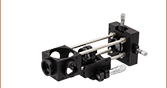
The K10CR1(/M) can be directly mounted to a Ø1/2" Post or Ø1" Post via 8-32 (M4) taps on two perpendicular edges. As shown in the image to the right, two Ø6 mm rods, such as our cage rods, can be used to align multiple rotation mounts along the same axis in post mounting applications (note that these two bores are not located at the correct spacing for attaching cage plates). Six 4-40 (M3) taps on the front surface of the moving dial allow components to be mounted, such as our K6A1 or K6A1/M Prism Mounting Adapter.
Alternatively, several mounting adapters are available below. The K10CR1A1 adapter plate facilitates mounting the K10CR1 horizontally, as shown in the image above. Secondly, the K10CR1A2(/M) plate is secured on the rotating dial to provide a variety of taps and a keyway for our flexure stage accessories. Finally, the K10CR1A3 bracket allows the K10CR1(/M) to be inserted within a 60 mm cage system.
| Specifications | |
|---|---|
| Mount Specifications | |
| Travel Range | 360° Continuousa |
| Maximum Speed | 10 Degrees/s |
| Minimum Speed | 0.005 Degrees/s |
| Maximum Accelerationb | 20 Degrees/s2 |
| Unidirectional Repeatabilityc | ±60 µrad |
| Backlash | ±200 µrad |
| Resolution (Theoretical) | 0.0000073° (0.128 µrad) |
| Maximum Load Capacityd | 22 N |
| Minimum Repeatable Incremental Movemente | 0.03° |
| Absolute Accuracyc | ±0.14° |
| Home Location Accuracy | ±100 µrad |
| Maximum Wobble (Axial) | 500 µrad |
| Motor Specifications | |
| Motor Type | 2-Phase Stepper Motor |
| Motor Drive Voltage | 8 V Nominal |
| Terminal Resistance | 20 Ω |
| Output Power | 2.5 W Nominal |
| Step Size | 1.8° |
| Rotor Inductance | 4.2 mH per Phase |
| Bearing Type | 4-Point Ball Bearing |
| Drive Mechanism | Worm Gear, Ratio 1:120 |
| Homing Limit Switch | Hall Effect |
| General Specifications | |
| Operating Temperature Range | 5 to 40 °C (41 to 104 °F) |
| Dimensions (L x W x H) | 107 mm x 66.0 mm x 21.5 mm (4.21" x 2.6" x 0.84") |
| Weight | 0.22 kg (0.48 lbs) |
Maximum Load Specification Details
| Parametera | Value |
|---|---|
| Max Load (Q) | 22 N (2.25 kg or 5.0 lbs) |
| Max Torque (Mz) | 140 mN•m |
| Max Transversal Torque (Mx) | 1.5 N•m |
| Typical Stiffness (Ka) | 380 µrad/N•m |
Resolution Calculation
For the stepper motor in the K10CR1(/M), there are 200 full steps per revolution of the motor and 2048 microsteps per full step. The output shaft of the motor goes into a 120:1 reduction gearbox.
The angular displacement of the rotation mount per encoder count is given by
200 x 2048 x 120 = 49,152,000.0 microsteps per revolution of the top platform
49,152,000.0/360 = 136533.33 microsteps per degree of movement.
K10CR1(/M) Pin Configurations
The USB 3.0 port is compatible with a USB 2.0 Micro B connector if the Micro B connector is plugged into the shaded region in the photo above. The I/O port requires a user-supplied 3.5 mm 4-way jack plug and cable; the pinout of the mating plug is shown to the right.
Compatible I/O Connector
3.5 mm 4-Way Jack Plug
This is the compatible connector for the I/O port; Thorlabs does not provide this connector.
Thorlabs offers two platforms to drive our wide range of motion controllers: our Kinesis® software package or the legacy APT™ (Advanced Positioning Technology) software package. Either package can be used to control devices in the Kinesis family, which covers a wide range of motion controllers ranging from small, low-powered, single-channel drivers (such as the K-Cubes™ and T-Cubes™) to high-power, multi-channel, modular 19" rack nanopositioning systems (the APT Rack System).
The Kinesis Software features .NET controls which can be used by 3rd party developers working in the latest C#, Visual Basic, LabVIEW™, or any .NET compatible languages to create custom applications. Low-level DLL libraries are included for applications not expected to use the .NET framework. A Central Sequence Manager supports integration and synchronization of all Thorlabs motion control hardware.

Kinesis GUI Screen
APT GUI Screen
Our legacy APT System Software platform offers ActiveX-based controls which can be used by 3rd party developers working on C#, Visual Basic, LabVIEW™, or any Active-X compatible languages to create custom applications and includes a simulator mode to assist in developing custom applications without requiring hardware.
By providing these common software platforms, Thorlabs has ensured that users can easily mix and match any of the Kinesis and APT controllers in a single application, while only having to learn a single set of software tools. In this way, it is perfectly feasible to combine any of the controllers from single-axis to multi-axis systems and control all from a single, PC-based unified software interface.
The software packages allow two methods of usage: graphical user interface (GUI) utilities for direct interaction with and control of the controllers 'out of the box', and a set of programming interfaces that allow custom-integrated positioning and alignment solutions to be easily programmed in the development language of choice.
A range of video tutorials is available to help explain our APT system software. These tutorials provide an overview of the software and the APT Config utility. Additionally, a tutorial video is available to explain how to select simulator mode within the software, which allows the user to experiment with the software without a controller connected. Please select the APT Tutorials tab above to view these videos.
Software
Kinesis Version 1.14.47
The Kinesis Software Package, which includes a GUI for control of Thorlabs' Kinesis and APT™ system controllers.
Also Available:
- Communications Protocol
Software
APT Version 3.21.6
The APT Software Package, which includes a GUI for control of Thorlabs' APT™ and Kinesis system controllers.
Also Available:
- Communications Protocol
The APT video tutorials available here fall into two main groups - one group covers using the supplied APT utilities and the second group covers programming the APT System using a selection of different programming environments.
Disclaimer: The videos below were originally produced in Adobe Flash. Following the discontinuation of Flash after 2020, these tutorials were re-recorded for future use. The Flash Player controls still appear in the bottom of each video, but they are not functional.
Every APT controller is supplied with the utilities APTUser and APTConfig. APTUser provides a quick and easy way of interacting with the APT control hardware using intuitive graphical control panels. APTConfig is an 'off-line' utility that allows various system wide settings to be made such as pre-selecting mechanical stage types and associating them with specific motion controllers.
APT User Utility
The first video below gives an overview of using the APTUser Utility. The OptoDriver single channel controller products can be operated via their front panel controls in the absence of a control PC. The stored settings relating to the operation of these front panel controls can be changed using the APTUser utility. The second video illustrates this process.
APT Config Utility
There are various APT system-wide settings that can be made using the APT Config utility, including setting up a simulated hardware configuration and associating mechanical stages with specific motor drive channels. The first video presents a brief overview of the APT Config application. More details on creating a simulated hardware configuration and making stage associations are present in the next two videos.
APT Programming
The APT Software System is implemented as a collection of ActiveX Controls. ActiveX Controls are language-independant software modules that provide both a graphical user interface and a programming interface. There is an ActiveX Control type for each type of hardware unit, e.g. a Motor ActiveX Control covers operation with any type of APT motor controller (DC or stepper). Many Windows software development environments and languages directly support ActiveX Controls, and, once such a Control is embedded into a custom application, all of the functionality it contains is immediately available to the application for automated operation. The videos below illustrate the basics of using the APT ActiveX Controls with LabVIEW, Visual Basic, and Visual C++. Note that many other languages support ActiveX including LabWindows CVI, C++ Builder, VB.NET, C#.NET, Office VBA, Matlab, HPVEE etc. Although these environments are not covered specifically by the tutorial videos, many of the ideas shown will still be relevant to using these other languages.
Visual Basic
Part 1 illustrates how to get an APT ActiveX Control running within Visual Basic, and Part 2 goes on to show how to program a custom positioning sequence.
LabVIEW
Full Active support is provided by LabVIEW and the series of tutorial videos below illustrate the basic building blocks in creating a custom APT motion control sequence. We start by showing how to call up the Thorlabs-supplied online help during software development. Part 2 illustrates how to create an APT ActiveX Control. ActiveX Controls provide both Methods (i.e. Functions) and Properties (i.e. Value Settings). Parts 3 and 4 show how to create and wire up both the methods and properties exposed by an ActiveX Control. Finally, in Part 5, we pull everything together and show a completed LabVIEW example program that demonstrates a custom move sequence.
Part 1: Accessing Online Help
Part 2: Creating an ActiveX Control
Part 3: Create an ActiveX Method
Part 4: Create an ActiveX Property
Part 5: How to Start an ActiveX Control
The following tutorial videos illustrate alternative ways of creating Method and Property nodes:
Create an ActiveX Method (Alternative)
Create an ActiveX Property (Alternative)
Visual C++
Part 1 illustrates how to get an APT ActiveX Control running within Visual C++, and Part 2 goes on to show how to program a custom positioning sequence.
MATLAB
For assistance when using MATLAB and ActiveX controls with the Thorlabs APT positioners, click here.
To further assist programmers, a guide to programming the APT software in LabVIEW is also available here.
Click to Enlarge
Figure 1: An example of how to read a vernier scale. The red arrow indicates what is known as the pointer. Since the tick mark labeled 10 on the vernier scale aligns with one of the tick marks on the main scale, this vernier scale is reading 75.60 (in whatever units the tool measures).
Reading a Vernier Scale
Vernier scales are typically used to add precision to standard, evenly divided scales (such as the scale on Thorlabs' rotation mounts). A vernier scale has found common use in many precision measurement tools, the most common being calipers and micrometers. The direct vernier scale uses two scales side-by-side: the main scale and the vernier scale. The vernier scale has a slightly smaller spacing between its tick marks (10% smaller than the main). Hence, the lines on the main scale will not line up with all the lines on the vernier scale. Only one line from the vernier scale will match well with one line of the main scale, and that is the trick to reading a vernier scale.
Figures 1 through 3 show a vernier scale system for three different situations. In each case, the scale on the left is the main scale, while the small scale on the right is the vernier scale. When reading a vernier scale, the main scale is used for the gross number, and the vernier scale gives the precision value. In this manner, a standard ruler or micrometer can become a precision tool.
The 0 on the vernier scale is the "pointer" (marked by a red arrow in Figs. 1 - 3) and will indicate the main scale reading. In Figure 1 we see the pointer is lined up directly with the 75.6 line. Notice that the only other vernier scale tick mark that lines up well with the main scale is 10. Since the vernier 0 lines up with the main scale’s 75.6, the reading from Figure 1 is 75.60 (in whatever units the tool measures in).
That is essentially all there is to reading a vernier scale. It's a very straightforward way of increasing the precision of a measurement tool. To expound, let’s look at Figure 2. Here we see that the pointer is no longer aligned with a scale line, instead it is slightly above 75.6, but below 75.7; thus the gross measurement is 75.6. The first vernier line that coincides with a main scale line is the 5, shown with a blue arrow. The vernier scale gives the final digit of precision; since the 5 is aligned to the main scale, the precision measurement for Figure 2 is 75.65.
Since the vernier scale is 10% smaller than the main scale, moving 1/10 of the main scale will align the next vernier marking. This asks the obvious question: what if the measurement is within the 1/10 precision of the vernier scale? Figure 3 shows just this. Again, the pointer line is in between 75.6 and 75.7, yielding the gross measurement of 75.6. If we look closely, we see that the vernier 7 (marked with a blue arrow) is very closely aligned to the main scale, giving a precision measurement of 75.67. However, the vernier 7 is very slightly above the main scale mark, and we can see that the vernier 8 (directly above 7) is slightly below its corresponding main scale mark. Hence, the scale on Figure 3 could be read as 75.673 ± 0.002. A reading error of about 0.002 would be appropriate for this tool.
As we've seen here, vernier scales add precision to a standard scale measurement. While it takes a bit of getting used to, with a little practice, reading these scales is fairly straightforward. All vernier scales, direct or retrograde, are read in the same fashion.
Click to Enlarge
Figure 2: An Example of a vernier scale. The red arrow indicates the pointer and the blue arrow indicates the vernier line that matches the main scale. This scale reads 75.65.
Click to Enlarge
Figure 3: An Example of a vernier scale. The red arrow indicates the pointer and the blue arrow indicates the vernier line that matches the main scale. This scale reads 75.67, but can be accurately read as 75.673 ± 0.002.
| Posted Comments: | |
Siyuan Qiu
(posted 2023-11-24 15:01:50.917) Dear Sir/Madam, our K10CR1 seems to stuck during rotation. We used the motion control software provided by Thorlabs, but while the angle reading of the software changes, our K10CR1 doesn't rotate physically. We would like to hear some advice on how to fix this problem. Thanks a lot! do'neill
(posted 2023-11-29 08:46:51.0) Response from Daniel at Thorlabs. I will reach out to you directly to help troubleshoot this with you. user
(posted 2023-08-02 15:41:30.97) Dear Sir/Ma'am, We are using K10CR1/M. During rotation, there were a range of position where the stepper motor would get stuck and would remain in same position while producing noise till the software updates the position. Kindly help urgently. fguzman
(posted 2023-08-03 07:45:46.0) Thanks for enquiry. Sorry to see you are having troubles with your stage. We will contact you directly to further troubleshoot this. user
(posted 2022-11-04 13:36:56.633) is the coding of this product the same as PRM1Z8? cwright
(posted 2022-11-04 10:24:30.0) Response from Charles at Thorlabs: Thank you for your query. The K10CR1 is a stepper motor and uses the integrated stepper motor dlls, while the PRM1Z8 would use the KcubeDCServo dlls. Other than this the process is the same and the same guides can be followed. Unfortunately as no contact information was left, we cannot reach out to help with this. Edmund Koch
(posted 2021-11-29 08:06:09.073) It would be very helpful if the TriggerOut signal could signal different positions. e.g. in regular intervals of 1°. Some kinesis devices can do so.
By this it would be possible to aquire data within one roundtrip without stopping the device, taking data and programming the new position. DJayasuriya
(posted 2021-12-03 03:48:46.0) Thank you for your inquiery. There may be a possibility of doing this. We will get in touch with you directly to discuss your application further. Tao Yuan
(posted 2021-11-23 17:18:49.397) I am using Matlab to control K10CR1/M, with APT active x object.
There are two errors:
1, I can not make h.MoveAbsolute() work.
The whole matlab will crash, with I run this function.
I run it like this:
h.SetAbsMovePos(0,135)
h.MoveAbsolute(0,true)
2, K10CR1 do not respond to some of the commands.
for example, I have this code:
.....
h.MoveJog(0,2);
.....
the function h.MoveJog might be skipped some time. DJayasuriya
(posted 2021-11-26 09:13:16.0) Thank you for your inquiery. We will get in touch with you directly to resolve your issue. Tao Yuan
(posted 2021-11-19 13:26:20.61) I am using APT server in MATLAB to control K10CR1/M. But whenever I set parameters by h.SetJogVelParams, I get no response from the system. Did I do something wrong? DJayasuriya
(posted 2021-11-22 04:39:04.0) Thank you for your inquiery, we will get in touch with you shortly to resolve your issue. DJayasuriya
(posted 2021-11-22 04:39:04.0) Thank you for your inquiery, we will get in touch with you shortly to resolve your issue. Hans K.
(posted 2021-08-12 19:50:16.603) Hello all,
during the initialization of the K10CR1 stage via C++ API, the command ISC_LoadSettings creates a memory exception, with which Windows then immediately terminates this application. This happens completely randomly and is annoying when initializing multiple such stages in a setup.
After weeks of communication with Thorlabs support, no one from the Thorlabs Software group seems to care. rcapehorn
(posted 2021-08-16 05:58:19.0) Response from Robert at Thorlabs. I apologise for the extended period in which your question has been open with us. I have checked with the software development team and can confirm that this is under active review, I apologise that this was not relayed to you. I am happy to share we have an interim solution for you, while the full investigation takes place. Your local tech support contact will follow up shortly. abhi akn
(posted 2021-06-22 16:20:00.287) Dear Sir/Ma'am,
We are using K10CR1/M. During 'homing' suddenly the stepper motor would get stuck after few steps and would remain in same position while producing noise till the software updates the position. We have faced this same issue while manual homing or using kinesis software for two different rotatoin stages. Kindly help urgently. user
(posted 2021-05-04 17:17:12.707) To whom it may concern,
I would like to integrate this rotator into a program where multiple pieces of equipment are being controlled by a host computer. However, I am using Labwindows/CVI and every resource I have found has been for LabVIEW. I found a document for host-controller communications for APT communications. Will this document provide the information I need to setup communication with the rotator? jcater
(posted 2021-05-05 12:19:09.0) Response from Jack at Thorlabs: Thank you for your inquiry. Whilst we do not directly support LabWindows CVI at this moment in time, I will reach out to you directly to try assist further. Alyssa Mutzafi
(posted 2021-05-04 20:35:03.847) Hi,
I would like to use two rotators in a LabVIEW program. Is it possible to use the same APT for both of them?
(We are now working with one and everything works fine)
Thank you jcater
(posted 2021-05-05 05:05:39.0) Response from Jack at Thorlabs: Thank you for your inquiry. Our APT software can be used to control multiple units at once. In LabVIEW you will have to create a new control for each individual unit. Jose Marticorena
(posted 2021-04-02 12:37:21.167) Hello,
I am looking to clarify what the requirements are to power the K10CR1/M; and to clarify what the I/O port requirments are...for example do we expect to supply the 5V/ground or is this provided by the stage? Yan Kai
(posted 2021-01-23 11:51:33.087) This motor can not work on well with APT, it will give me a error when i use the software with APT. I can not be solved even i asked help from the engineer. cwright
(posted 2021-01-26 03:11:24.0) Response from Charles at Thorlabs: Hello and thank you for contacting us. I am sorry to hear you are having issues but I am sure we will be able to resolve this. Uunfortunately I cannot find an email or case regarding the issue so we will need to reach out by email for some more details. Joshua Clayton
(posted 2019-12-12 18:40:40.967) Hi! We're going to put the K10CR1 into a commercial LiDAR product.
We have a pair of K10CR1, which is part of a testbench system in the lab, where the windows GUI is fine for controlling, them, however, The end product will be a small form factor Linux machine.
A little googling led me to https://www.thorlabs.com/software/apt/APT_Communications_Protocol_Rev_15.pdf
and https://github.com/UniNE-CHYN/thorpy, but nothing specific to the K10CR1 for Linux; What is the best resource for learning to move it programatically from Linux? DJayasuriya
(posted 2019-12-17 08:27:23.0) Response from Dinuka at Thorlabs: Hello, thank you for your query. Unfortunately, neither Kinesis, nor APT, nor their respective APIs are compatible with Linux. KDC10CR1 can be controlled from a Linux system only via serial commands. The documentation of Kinesis' & APT's serial communications protocol can be found on our website. We also have plenty of examples, internally, of scripts written in various languages (C++, Python, MATLAB, LabVIEW) which make use of these commands. If you would like copies of these example scripts, please contact your local technical support office. Andrew Hillier
(posted 2019-12-11 14:56:46.643) Can the APT or Kinesis software operate this rotation stage using the USB 2.0 mini plug, or does it need to use the USB 3.0? DJayasuriya
(posted 2019-12-12 09:23:54.0) Response from Dinuka at Thorlabs: Hello, thank you for your feedback. The unit is designed to for USB 3 connection it can also be powered using a Micro B USB 2 connection. Yes this stage can be controlled using APT or Kinesis software. Hope this helps. user
(posted 2019-10-17 20:32:53.233) This is an amazing product. It provides flexible mounting options along with the utility of rotating optical elements.
However, I think that there should be a version of this product that allows for higher rotation speeds.
One such product (along with a piece of ground glass on an SM-threaded mount) would provide a complete solution for setting up a rotating diffuser, which is necessary in many systems for turning spatially coherent light into incoherent light. This would save customers the need of having to buy everything separetely and building the system from scratch. We would have the option of just buying that high-speed motorized rotation mount along with a piece ground glass -both from the Thorlabs catalog- and get our rotating diffusers without much more trouble. AManickavasagam
(posted 2019-10-18 10:50:25.0) Response from Arunthathi at Thorlabs: Thanks for your feedback. I will relay your feedback internally. Though we do not have an equivalent high speed version (with 1” aperture), just to let you know we do offer a high speed compact rotation mount such as the DDR25 that has optical threading which you could use to mount a ground glass and is cage compatible. Please feel free to contact your local tech support office if you would like to discuss further regarding your application and suitability. Richard Grzebieta
(posted 2019-05-29 03:19:53.463) Hi I would like to mount the K10CR1/M upside down and have the load in the z (Hanging off it) direction. Will the max load of 22N still apply? rmiron
(posted 2019-05-29 10:18:50.0) Response from Radu at Thorlabs: Hello, Richard. I am not sure that I correctly understand what configuration you have in mind, but the answer can be found in the information posted in the "Specs" tab. In a nutshell, if that 22 N load will not be applying more than 140 mN*m about the axis of rotation or more than 1.5 N*m about axes located in the plane of rotation, then the stage should operate nominally and meet all of its other specifications. user
(posted 2019-03-27 13:02:29.71) Dear all
I'd like to use the K19CR1/M motor with an extension cable (1.8m) and the cable (1.5m) included in the delivery. Unfortunately the control software doesn't work properly anymore like this. Jogs still work but when I try to move to a defined angle I get a timeout error. Do you have an idea for a solution? user
(posted 2019-03-28 12:00:46.0) Response from Radu at Thorlabs: The fact that jogs run successfully while moves result in timeout errors tells us that the messages sent by K10CR1/M to your PC are not seen, even though K10CR1/M successfully reads the messages coming from your PC. That might be a consequence of high unidirectional losses at the junction between the two cables. I suggest that you replace them with a cable that is long enough to connect the two devices directly. There is significant variation in the quality of USB cables available on the market. A couple of the companies that we know to provide USB cables of consistent quality are CIE Group & Space Shuttle Hi-Tech, so it might be worth trying to source them from there. naveenballa
(posted 2019-01-23 17:23:14.707) Hi,
I have a labview related query. I am trying to use this motor to rotate my polarizer in steps and measure my signal after each rotation step. I am using APT controls with labview. I want to make sure the motor has stopped before I measure the signal. If anyone has an example code on how to implement this, please share. I can use a waiting step after each rotate command but I am looking for an alternative solution. Thanks! rmiron
(posted 2019-04-09 05:13:33.0) Response from Radu at Thorlabs: The "MoveRelative (int waitTimeout)" and "MoveAbsolute (int waitTimeout)" methods return upon the completion of the demanded move, provided that the waitTimeout parameter is larger than the time it takes the move to complete (in ms). Therefore, I suggest that you place one of these commands and the command for measuring the signal, in separate frames of a flat sequence. That will ensure that the stage is not moving when a measurement is taken and vice-versa. ckwjp327
(posted 2018-08-22 18:55:36.71) Dear all,
I would like to ask if there is any difference using the USB2.0 and USB3.0 cable for K10CR1? Sometimes "FT_IO_ERROR" will be shown. the powered USB 3.0 hub is used to drive the K10CR1, also the mobile phone and USB relay board are also connected to the same hub?
Or any standard on the USB cable? As sometimes the power LED flashes but do not rotate.
Thank you very much! AManickavasagam
(posted 2018-08-24 05:42:50.0) Response from Arunthathi @ Thorlabs: Thanks for your query. For data exchange the K10CR1 would be USB 2 compatible, the unit has USB 3 port for providing sufficient power without the need for using external power supply. FT_IO_ERROR suggests that an error has occurred while reading the data from the device, like a USB disconnect has occurred.
I have contacted you directly to troubleshoot the issue you have. user
(posted 2018-07-12 11:33:53.46) Dear all,I'm controlling the motor doing experiment,since i need big amount of data,the motor moved all day,and then it became unstable,sometimes it can‘t respond to my MOVE, HOME,JOG instructions both under your kinesis GUI,did the motor break and can it be corrected?thank you AManickavasagam
(posted 2018-07-17 09:09:38.0) Response from Arunthathi at Thorlabs: Thanks for your query. We would need further details from you to troubleshoot and assist with the issue you have. Please contact your local tech suppport office for assistance. mailfert
(posted 2018-05-14 13:31:26.013) Dear all,
Since my previous post, I'm not able to go to an absolute position only (everything else is OK for me).
Could you tell me which function should I use to move to an absolute position please?
Best regards, it's close to be an emergency...
Sébastien Mailfert bhallewell
(posted 2018-05-22 08:17:41.0) Response from Ben at Thorlabs: Thank you for your feedback. In future, I would recommend directly emailing your local Tech Support teams to resolve this issue.
You will need to ensure that you have called SetMoveAbsolutePosition(position) & assigned a 'position' value. This will then enable you to wire an Invoke Node for a MoveAbsolute(waitTimeout) command whereby the Timeout is a finite amount of time in which the move should return a MoveComplete message.
I will contact you to ensure this is working for you. mailfert
(posted 2018-05-11 11:10:52.747) Dear all,
I'm controlling the motor with LabVIEW.
I'm able to program some commands (Go home, move one step in one direction or the opposite one).
But I'm not able to:
1- go to an absolute position (I tried "MoveAbsolute" without success)
2- set the step size
I can control these parameters via the interface but not via "Invoke Mehod node".
Best regards sibo
(posted 2017-10-31 12:27:38.167) Which is the kind of stastistic distribution followed by the absolute accuracy ? I supposed is following a normal distribution. The +/- 0.14d, is it equal to one or two standard deviation?
Thank you in advance. bwood
(posted 2017-11-06 05:58:31.0) Response from Ben at Thorlabs: Thank you for your feedback. You are correct that we use a normal distribution, and our specifications are generally based on two standard deviations. garyliu127
(posted 2017-08-29 10:50:45.907) Hi,
We ran into some problem when using 2 sets of K10CR1 in our machine. The resource and power in the computer might not be enough which cause our program not functioning properly. Therefore, we want to know is there an additional power supply for K10CR1/M, and what are the specs for the power supply such as the voltage? current?
Thank you bwood
(posted 2017-08-31 06:25:18.0) Response from Ben at Thorlabs: Thank you for your feedback. There isn't an alternative power supply; the power supplied by the USB connection should be enough. I would suggest introducing a powered USB hub, which should be able to provide enough power. yyh3190
(posted 2017-06-13 10:13:34.05) hi
i use the K10cr1/m rotating stage
how can use the kinesis software in matlab? bwood
(posted 2017-06-13 08:19:06.0) Response from Ben at Thorlabs: Thank you for your feedback. Kinesis has a full .NET API, which can be used with a wide range of third party software, including MatLab. I would suggest taking a look at the ".NET API Help" file, installed with Kinesis. Feel free to contact your local tech support office with any questions which arise from the file. xjiang225
(posted 2017-05-11 18:48:39.027) I'm using the communication protocol to send commands to the K10CR1. Some of the messages are useful(such as home and jog), but I can't get some other messages work, such as MGMSG_MOT_MOVE_RELATIVE on pg.55 and MGMSG_MOT_MOVE_ABSOLUTE on pg.58. I think I have read the protocol carefully but can't figure out why. Can you send me an example(long version) on either of these commands with K10CR1?Thank you very much! bwood
(posted 2017-05-12 05:59:35.0) Response from Ben at Thorlabs:Thank you for using our feedback feature. The easiest way to generate serial communications examples is directly through Kinesis, our motion control software. Firstly, download the software and begin controlling the stage. If you can then open "File" then "Options". On the "Application Options" tab press Ctrl+APT on your keyboard. This will allow you to expose the serial commands Kinesis is using to control the K10CR1 in real time. From this point, you can effectively generate example messages for any possible function of the stage. I hope this methodology helps, but feel free to contact me at techsupport.uk@thorlabs.com, if you have any difficulties or further questions. joos
(posted 2016-10-24 11:13:48.377) Dear Sir / Madam,
I am currently interfacing the K10CR1 with python using the APT.dll of the APT User version 3.3.6064.16307. I am assuming the hardwaretype HWtype is 50 because it is the only one to work but can you confirm me this please. I am also facing the following problem that the velocity parameters after initialisation with InitHWDevice() are too low (typically 0.017 °/s instead of 10°/s even though MOT_GetVelParams() returns good values) and I have to explicitly specify them using MOT_SetVelParams().
I don't have the problem with the controller TDC001 interfaced as HWtype 31. Can you help me on this ?
Maxime Joos bhallewell
(posted 2016-10-28 09:59:42.0) Response from Ben at Thorlabs: Thank you for getting in touch with us. I invite you to take a look at our Communication Protocol document within the following link.
https://www.thorlabs.de/Software/Motion%20Control/APT_Communications_Protocol_Rev_18.pdf
Checking the details of this method on pg.38 this may stem from the conversion factors used in the Get/SetVelParams method for the K10CR1. Within pg.16 & 17 of the communications protocol we outline the conversion between microstep counting & 'real world' units of position, velocity & acceleration for various stepper-actuated stages. We unfortunately have not updated this document to include conversions for our K10CR1 stage. We will update the document to include these conversions & I will send you a copy directly. frolovtsev
(posted 2016-10-16 13:24:22.823) I noticed that my stepper motor (s/n 55000282) skips steps, but the position counter works like without missing. Is the problem with missing steps solvable? Thank you. msoulby
(posted 2016-10-19 09:19:02.0) Response from Mike at Thorlabs: We will contact you directly to troubleshoot this problem with you. gronle
(posted 2016-07-13 15:30:14.483) I use the C++ library of Kinesis to access to K10CR1. We have two K10CR1s connected to the computer. Both serial numbers are recognized, however the command TLI_GetDeviceInfo always returns the TLI_DeviceInfo struct filled with information of the first device, only, independent if the given serialNo is the one from the first or second device. However, serialNo which does not correspond to any device lead to an error. Might this be a bug in the Kinesis software (1.6.0)?
Thank you msoulby
(posted 2016-07-14 10:57:28.0) Response from Mike at Thorlabs: We will contact you directly to dicuss this with you in more detail. samini79
(posted 2016-07-07 17:31:36.44) Os of my computer is window xp and versions of ATP config and user are 1.1.0 and 2.3.4701.37075. In this situation, K10CR1/M is not connected with my computer. error code = 10001, internal code = 13560709, 13520709. So I download new version of ATP and Kinesis, but installations are failed because the new programs are not suitable to window xp. Would you provide some solution about recognization of K10CR1/M in window XP? Thank you. bhallewell
(posted 2016-07-07 08:37:51.0) Response from Ben at Thorlabs: Thank you for your question here. Support was added for K10CR1 upon release of the item early last year. APT V3.4.0 is the oldest version of software which can support the stage, which unfortunately is not compatible with Windows XP. mccully
(posted 2016-06-16 22:56:06.323) I have had no luck with APT or kinesis software in controlling the K10 rotary stage. The APT does not recognize the motor. The Kinesis software says "caught exception: BuildDeviceList failed error code 7". This device is a paperweight if it can not be controlled.
Thank you. bwood
(posted 2016-06-17 04:04:56.0) Response from Ben at Thorlabs: I am sorry to hear about your problems with our K10CR1 rotary stage. We will be contacting you directly to gather more information on your setup, and to troubleshoot this issue further. mccully
(posted 2016-06-16 22:36:51.29) I have been unable to get the APT software to work. I have tried multiple versions. I have tried multiple PCs (windows 7 and windows 8). The software will not allow motor selection in the configuration software (only option is "none"), and absolutely nothing comes up in the user software. I have had no luck using labview basic examples to control the motor as well. Dear Sir or Madam,
I use Windows XP on my computer. I know that this version of Windows is not supported any more by APT software.
Would you kindly provide me a last stable version of APT, which is compatible with Windows XP? cevered
(posted 2015-12-16 05:25:00.0) Thank you for your feedback. We can indeed supply an archived version of APT which is compatible with Windows XP. I will be in contact via email with a link to the set up file. |
Rotation Mount and Stage Selection Guide
Thorlabs offers a wide variety of manual and motorized rotation mounts and stages. Rotation mounts are designed with an inner bore to mount a Ø1/2", Ø1", or Ø2" optic, while rotation stages are designed with mounting taps to attach a variety of components or systems. Motorized options are powered by a DC Servo motor, 2 phase stepper motor, piezo inertia motor, or an Elliptec™ resonant piezo motor. Each offers 360° of continuous rotation.
Manual Rotation Mounts
| Rotation Mounts for Ø1/2" Optics | |||||||
|---|---|---|---|---|---|---|---|
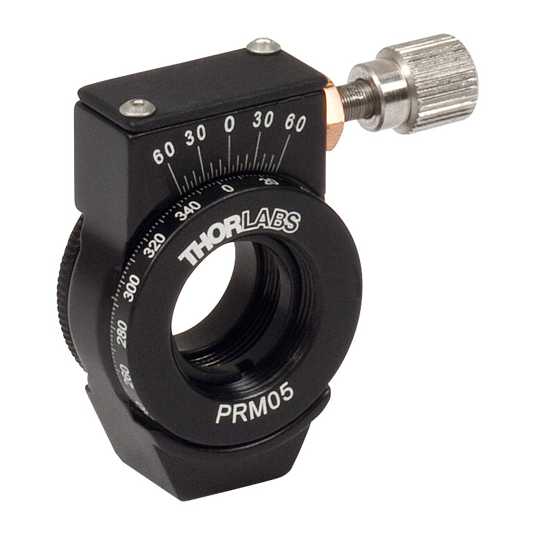
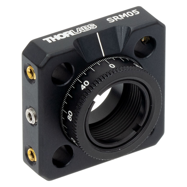
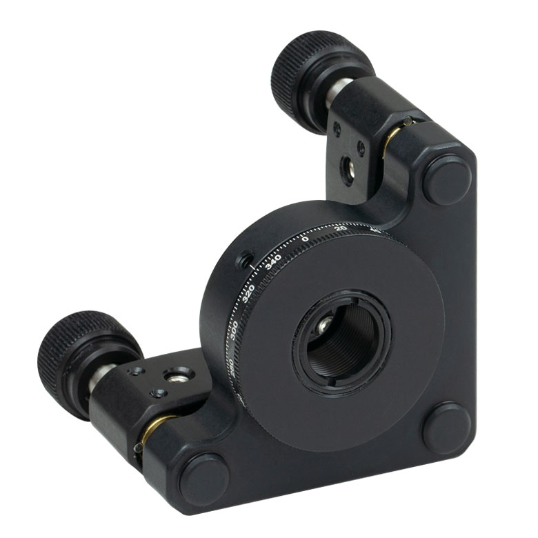
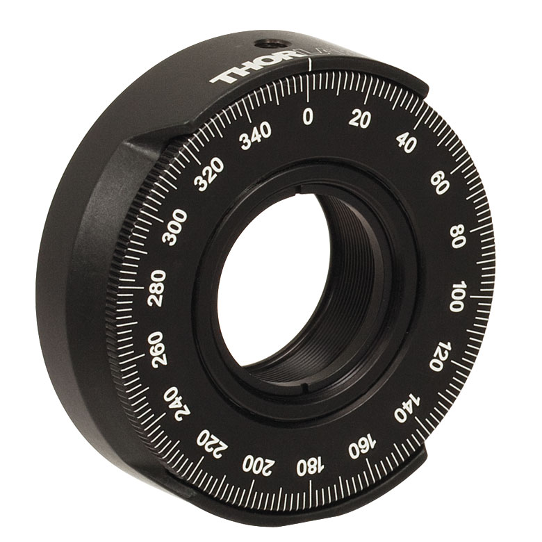
| Item # | MRM05(/M) | RSP05(/M) | CRM05 | PRM05(/M)a | SRM05 | KS05RS | CT104 |
| Click Photo to Enlarge |
 |
 |
 |
 |
 |
 |
 |
| Features | Mini Series | Standard | External SM1 (1.035"-40) Threads |
Micrometer | 16 mm Cage-Compatible | ±4° Kinematic Tip/Tilt Adjustment Plus Rotation | Compatible with 30 mm Cage Translation Stages and 1/4" Translation Stagesb |
| Additional Details | |||||||
| Rotation Mounts for Ø1" Optics | ||||||||
|---|---|---|---|---|---|---|---|---|
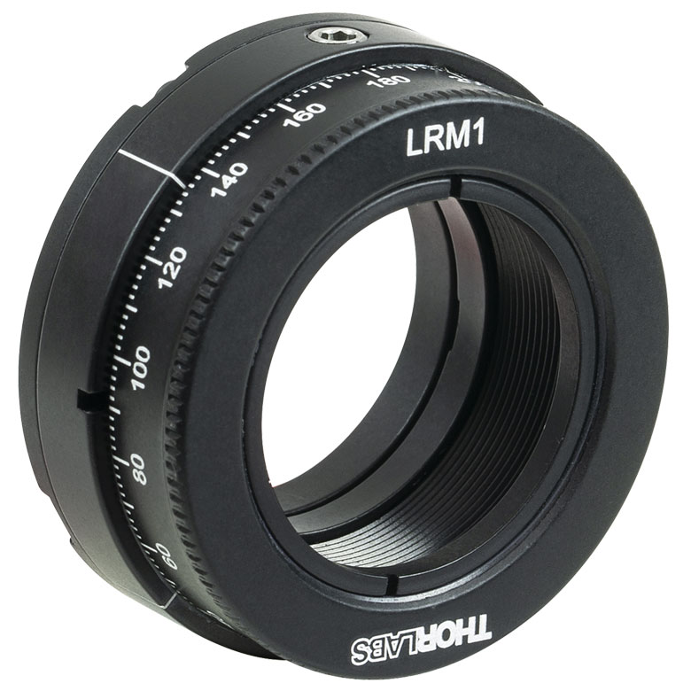
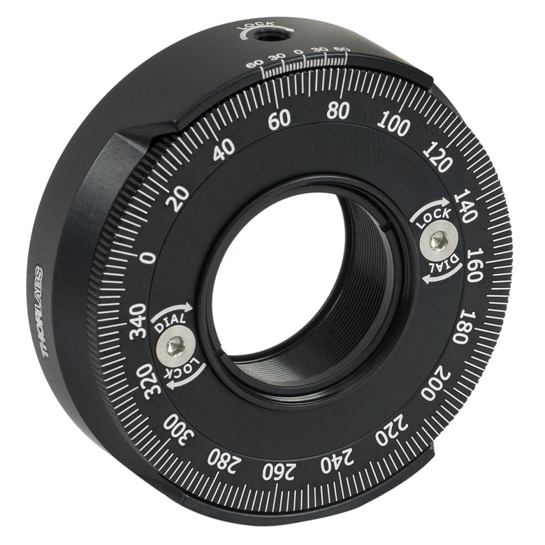
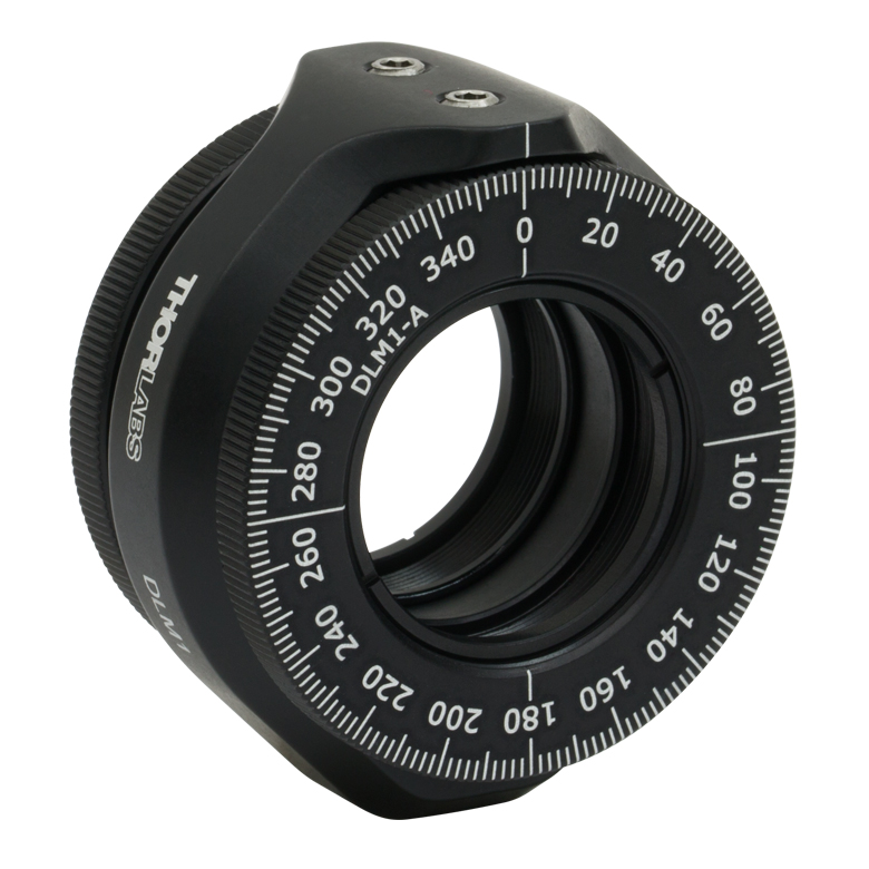
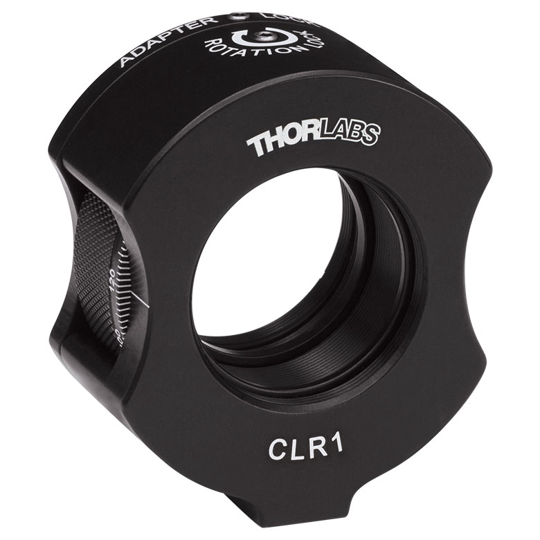
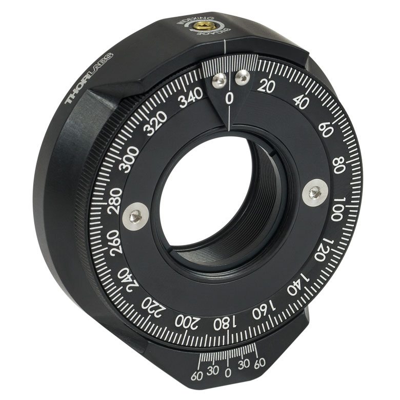
| Item # | RSP1(/M) | LRM1 | RSP1D(/M) | DLM1(/M) | CLR1(/M) | RSP1X15(/M) | RSP1X225(/M) | PRM1(/M)a |
| Click Photo to Enlarge |
 |
 |
 |
 |
 |
 |
|
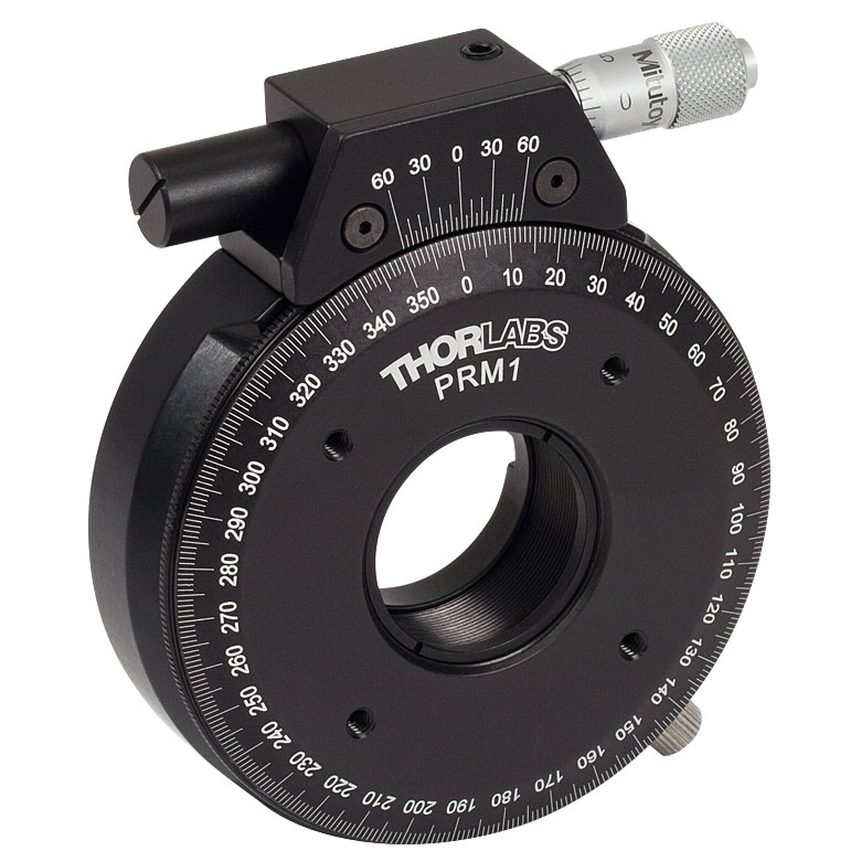 |
| Features | Standard | External SM1 (1.035"-40) Threads |
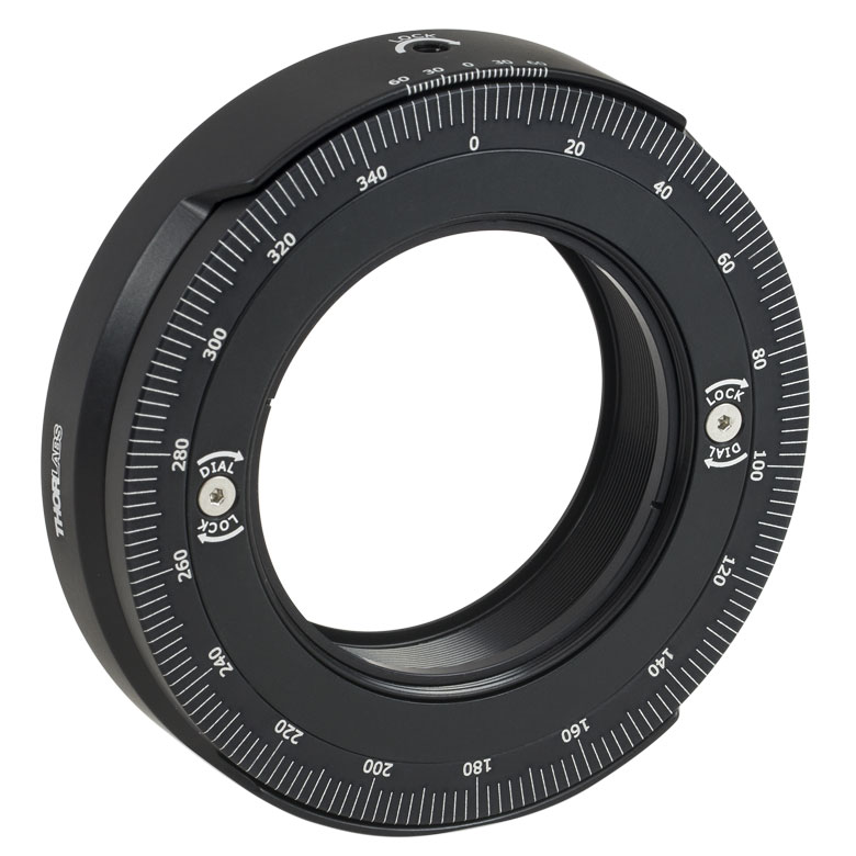
Adjustable Zero | Two Independently Rotating Carriages | Rotates Optic Within Fixed Lens Tube System |
Continuous 360° Rotation or 15° Increments |
Continuous 360° Rotation or 22.5° Increments |
Micrometer |
| Additional Details | ||||||||
| Rotation Mounts for Ø1" Optics | ||||||
|---|---|---|---|---|---|---|
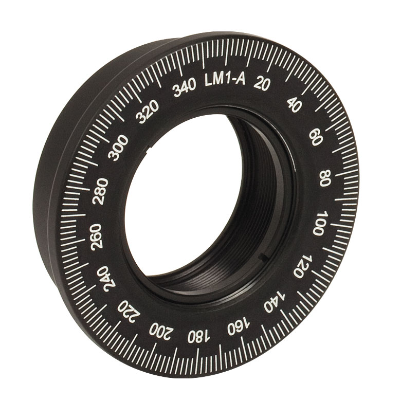
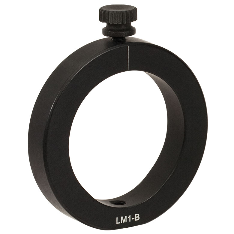
| Item # | LM1-A & LM1-B(/M) |
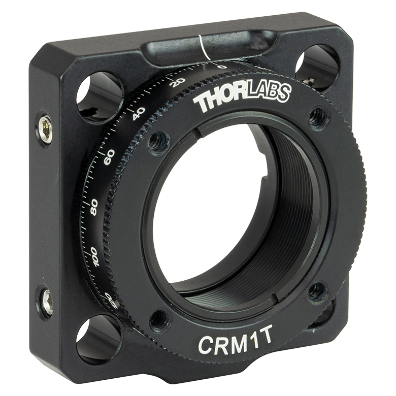
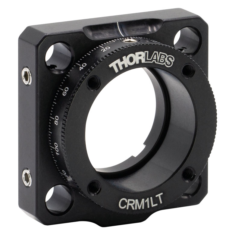
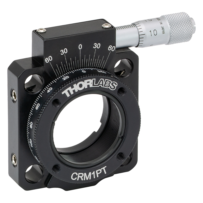
CRM1T(/M) | CRM1LT(/M) | CRM1PT(/M) | KS1RS | K6XS |
| Click Photo to Enlarge |
  |
 |
 |
 |
 |
 |
| Features | Optic Carriage Rotates Within Mounting Ring | 30 mm Cage-Compatiblea | 30 mm Cage-Compatible for Thick Opticsa |
30 mm Cage-Compatible with Micrometera |
±4° Kinematic Tip/Tilt Adjustment Plus Rotation | Six-Axis Kinematic Mounta |
| Additional Details | ||||||
| Rotation Mounts for Ø2" Optics | |||||||
|---|---|---|---|---|---|---|---|
| Item # | RSP2(/M) | RSP2D(/M) | PRM2(/M) | LM2-A & LM2-B(/M) |
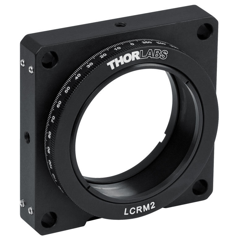
LCRM2(/M) | KS2RS | K6X2 |
| Click Photo to Enlarge |  |
 |
 |
  |
 |
 |
 |
| Features | Standard | Adjustable Zero |
Micrometer | Optic Carriage Rotates Within Mounting Ring | 60 mm Cage-Compatible | ±4° Kinematic Tip/Tilt Adjustment Plus Rotation | Six-Axis Kinematic Mount |
| Additional Details | |||||||
Manual Rotation Stages
| Manual Rotation Stages | ||||||
|---|---|---|---|---|---|---|
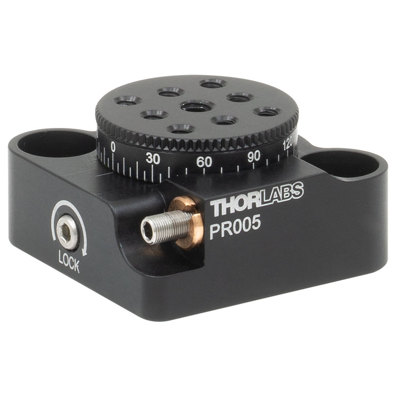
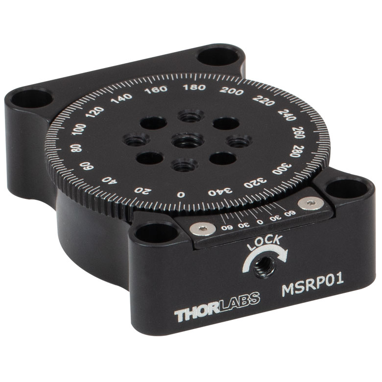
| Item # | RP005(/M) | PR005(/M) | MSRP01(/M) | RP01(/M) | RP03(/M) | QRP02(/M) |
| Click Photo to Enlarge |
 |
 |
 |
 |
 |
 |
| Features | Standard | Two Hard Stops | ||||
| Additional Details | ||||||
| Manual Rotation Stages | ||||||
|---|---|---|---|---|---|---|
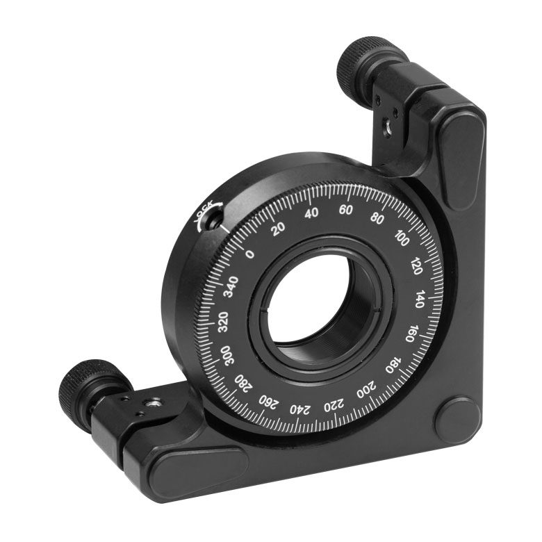
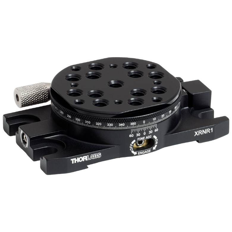
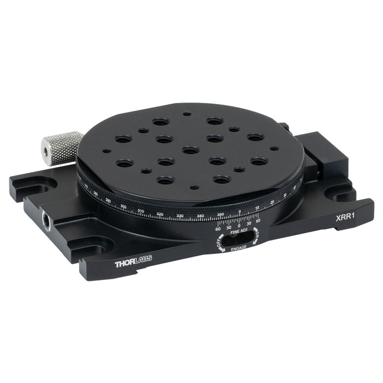
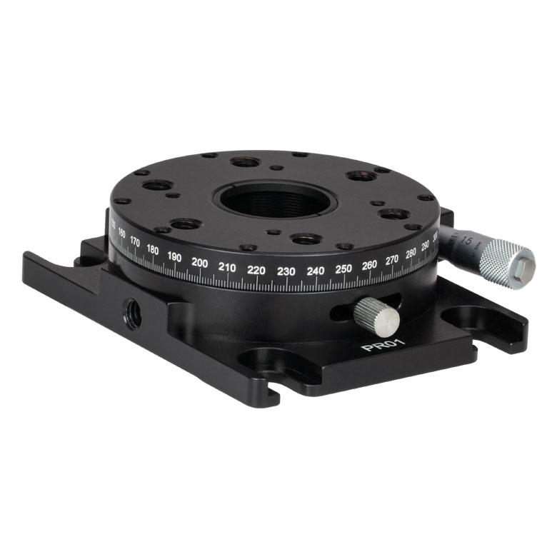
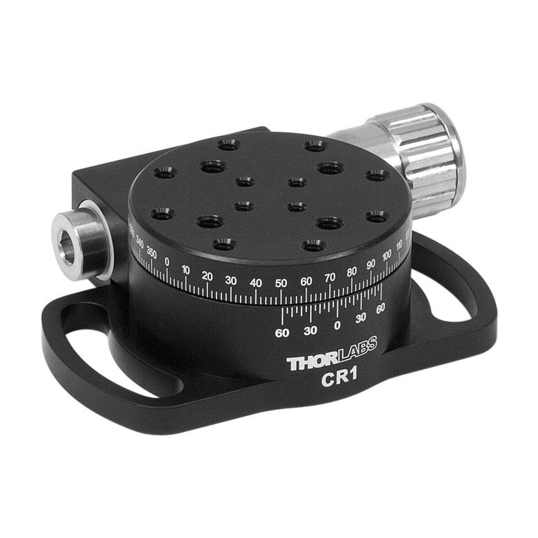
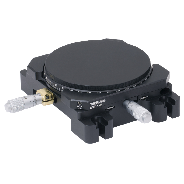
| Item # | XRNR1(/M) | XRR1(/M) | PR01(/M) | CR1(/M) | XYR1(/M) | OCT-XYR1(/M) |
| Click Photo to Enlarge |
 |
 |
 |
 |
 |
 |
| Features | Fine Rotation Adjuster and 2" Wide Dovetail Quick Connect |
Fine Rotation Adjuster and 3" Wide Dovetail Quick Connect |
Fine Rotation Adjuster and SM1-Threaded Central Aperture |
Fine Pitch Worm Gear | Rotation and 1/2" Linear XY Translation | |
| Additional Details | ||||||
Motorized Rotation Mounts and Stages
| Motorized Rotation Mounts and Stages with Central Clear Apertures | |||||
|---|---|---|---|---|---|
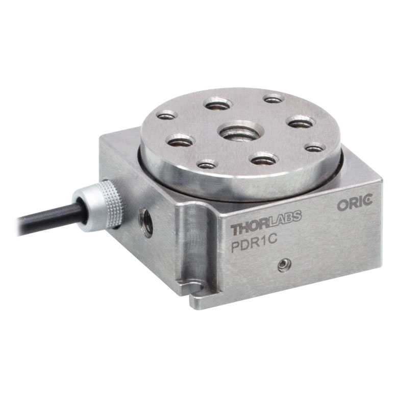
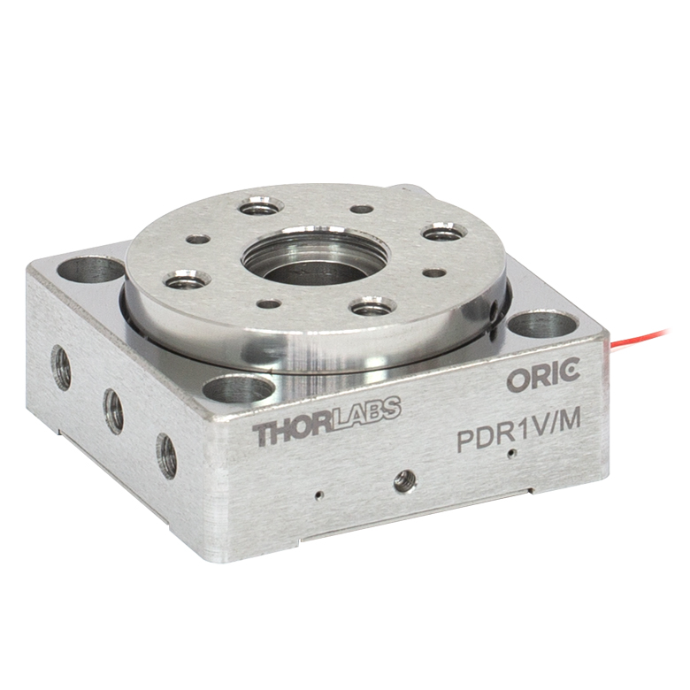
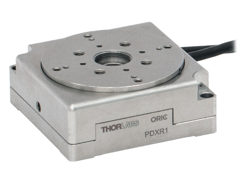
| Item # | DDR25(/M) | PDR1C(/M) | PDR1(/M) | PDR1V(/M) | PDXR1(/M) |
| Click Photo to Enlarge |
 |
 |
 |
 |
 |
| Features | Compatible with SM05 Lens Tubes, 16 mm Cage System, & 30 mm Cage System |
Compatible with 16 mm Cage System |
Compatible with SM05 Lens Tubes & 30 mm Cage System |
Vacuum-Compatible; Also Compatible with SM05 Lens Tubes & 30 mm Cage System |
Compatible with SM05 Lens Tubes & 30 mm Cage System |
| Additional Details | |||||
| Motorized Rotation Mounts and Stages with Central Clear Apertures | |||||
|---|---|---|---|---|---|
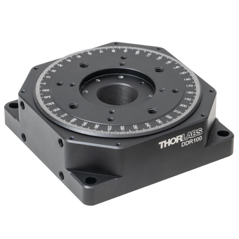
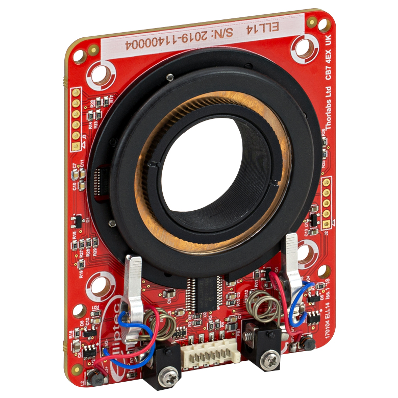
| Item # | K10CR1(/M) | PRM1Z8(/M)a | DDR100(/M) | ELL14 | HDR50(/M) |
| Click Photo to Enlarge |
 |
 |
 |
 |
 |
| Features | Compatible with SM1 Lens Tubes & 30 mm Cage System | Compatible with SM1 Lens Tubes, 16 mm Cage System, 30 mm Cage System |
Compatible with SM1 Lens Tubes, Open Frame Design for OEM Applications |
Compatible with SM2 Lens Tubes |
|
| Additional Details | |||||
| Motorized Rotation Mounts and Stages with Tapped Platforms | ||
|---|---|---|
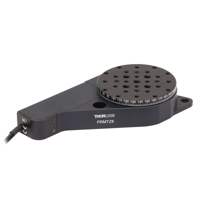
| Item # | PRMTZ8(/M)a | ELL18(/M)b |
| Click Photo to Enlarge |
 |
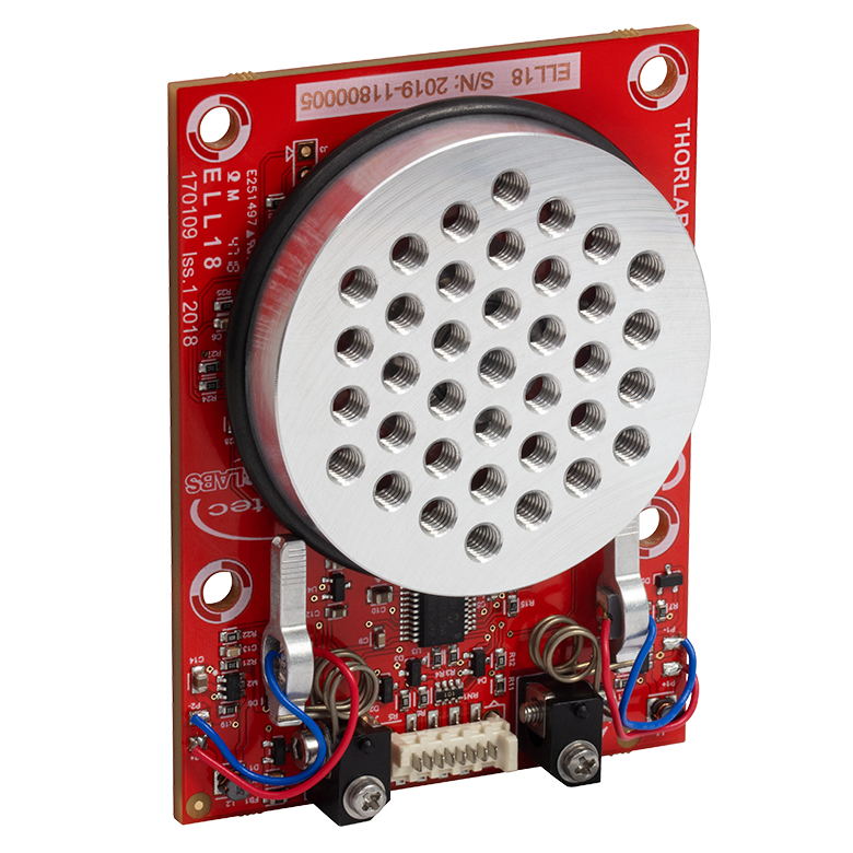 |
| Features | Tapped Mounting Platform for Mounting Prisms or Other Optics | Tapped Mounting Platform, Open Frame Design for OEM Applications |
| Additional Details | ||

 Zoom
Zoom- Full Bidirectional 360° Rotation
- SM1 (1.035"-40) Threading for Mounting Ø1" Lens Tubes
- Four 4-40 Tapped Holes for 30 mm Cage Systems on Each Side of Housing
- Compact Size: 4.21" x 2.60" x 0.84" (107.0 mm x 66.0 mm x 21.5 mm)
- Two SM1RR Retaining Rings Included
Adapters are available that allow the user to mount the K10CR1(/M) directly to a table, add a tapped platform, or integrate it into a 60 mm cage system. These adapters are sold separately below.
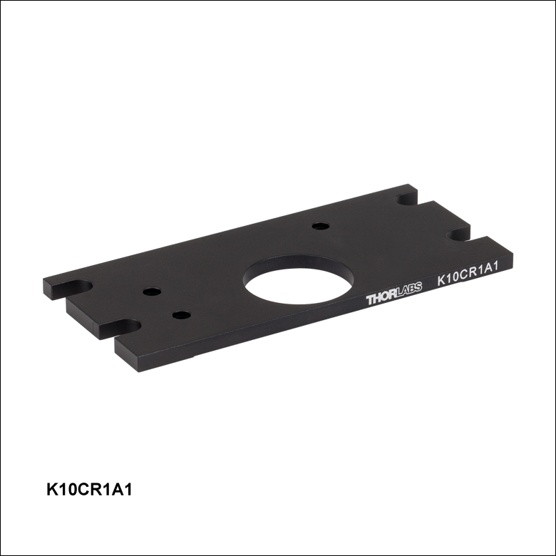
Table Mounting Adapter
The K10CR1A1 Mounting Plate is designed to mount the K10CR1(/M) rotation mount horizontally to an optical table or breadboard for use as a rotation stage. The plate comes with three 8-32 and three M4 button head screws for attaching an imperial or metric stage, respectively. Four slots accept 1/4" or M6 screws, which are ideal for securing the stage to a breadboard.
Click to Enlarge
The K10CR1 attached to a K10CR1A1 Mounting Plate, with a K10CR1A2 adapter plate attached to the moving world.
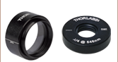
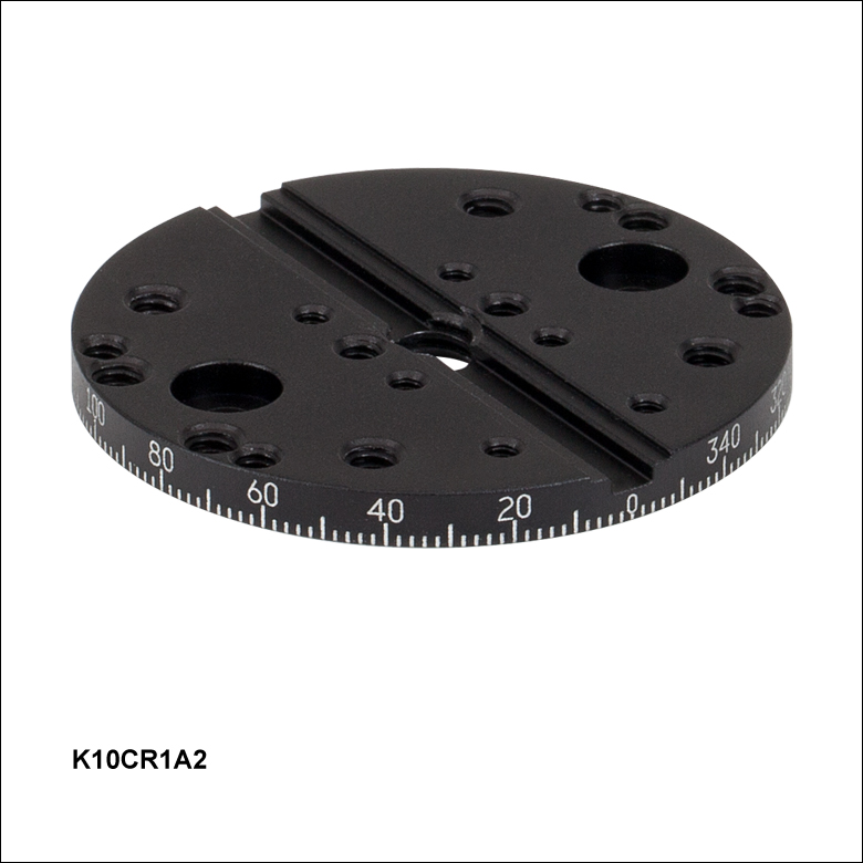
Rotating Platform Adapter
When the stage is mounted horizontally, the SM1 mounting feature may not be needed. In these cases, the K10CR1A2(/M) adapter plate attaches to the surface of the rotating dial with two included 4-40 (M3) button head screws. This Ø1.81" (Ø46.0 mm) plate provides a central 3.0 mm groove and 6-32 (M3) taps for attaching Thorlabs' flexure stage accessories. In addition, an array of six 2-56 (six M2), six 4-40 (two M2.5 and four M3), eight 6-32 (four M3 and four M4), and one 1/4"-20 (M6) taps allow for a variety of optomechanical components to be attached, including GN05 (GN05/M) Goniometers, PM3 (PM3/M) Prism Clamping Arms, and T12X (T12X/M) and MS1 (MS1/M) Translation Stages.
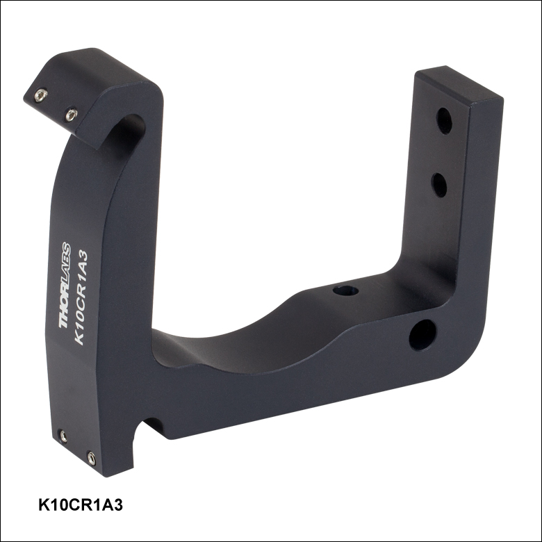
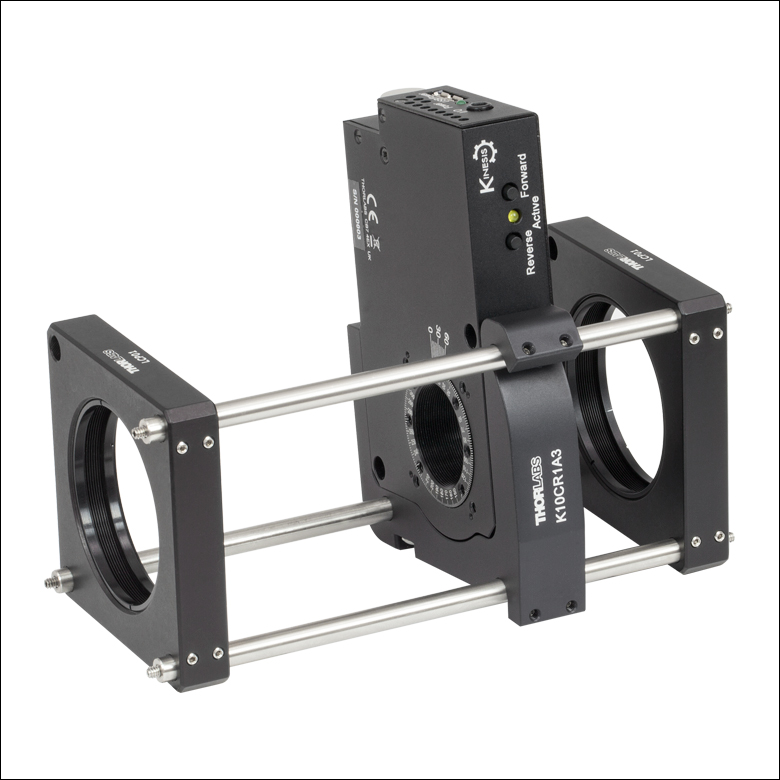

60 mm Cage System Adapter
The K10CR1A3 is a bracket that attaches to the edge of the K10CR1(/M) and allows the rotation mount to be integrated into 60 mm Cage Systems. The K10CR1A3 comes with three 8-32 and three M4 button head screws for attaching the bracket to both imperial and metric stages.
Once the bracket is attached to the stage, one cage rod is slid through the Ø6 mm bore in the bracket. Slots on the other edge of the bracket allow the rotation mount to pivot outside of the cage system for installation of optics or other components, as shown in the photos to the right. The design limits the number of cage rods used in a cage segment containing the rotation mount to three. A 0.050" hex key is included for tightening the locking setscrews onto the cage rods.
Please note that the K10CR1A3 bracket mounts the stage inside the 60 mm cage system at a 7° angle. While a fixed 30 mm cage system can still be attached to the front and back faces of the K10CR1(/M), the 30 and 60 mm cage system rods will not be aligned, although the optic axes will be collinear.