ORIC® Piezo Inertia Stage Controllers
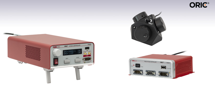
- Multichannel or Compact Single Channel Controller Versions
- Open- and Closed-Loop Operation
- High Positioning Resolution Up to 10 nm
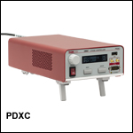
PDXC
ORIC® Piezo Inertia Stage Controller
MCMK3
USB HID Joystick
PDXC2
Compact ORIC® Piezo Inertia Stage Controller

Please Wait
| Table 1.1 Compatible ORIC® Piezo Inertia Stages |
|---|
| 4.5 mm Vertical Translation Stage |
| 5 mm Linear Translation Stages |
| 12 mm Linear Translation Stages |
| 20 mm Linear Translation Stages |
| 50 mm Linear Translation Stages |
| Rotation Stages |
| Vacuum-Compatible Stages |
Features
- Two Controller Versions:
- PDXC Controller with Standalone or PC Operation and Multi-Stage Control
- PDXC2 Controller with Compact Design, Single Channel, and PC Only Control
- Supports Both Open- and Closed-Loop Operation
- Compatible with ORIC Piezo Inertia Linear, Vertical, and the PDR1C(/M) and PDXR1(/M) Rotation Stages (See Table 1.1)
- High Current Coupled with Optimized Waveforms Stably Drive Stages at Up to 20 mm/s
- High Positioning Resolution Up to 10 nm
- Optimized PID Parameters Provide ±2% Speed Deviation in Closed-Loop Mode
- Stage Stays at Any Precise Position Within a 10 nm Range With Dynamic Adjustment in Closed-Loop Mode [PDX1(/M) Stage Only]
- Optional Joystick Accessory and Extension Cable Available Separately Below
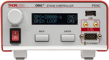
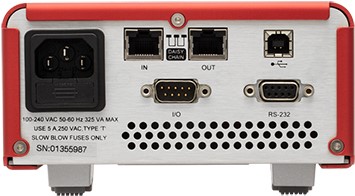
Thorlabs' ORIC® Piezo Inertia Stage Controllers operate the ORIC linear, vertical, or rotation (Item # PDR1C(/M) and PDXR1(/M)) piezo inertia drive stages. They offer both open- and closed-loop control, drive speeds up to 20 mm/s, and up to 10 nm position resolution on select ORIC stages. The PDXC controller can be operated with the on-unit buttons and display, or with a PC connection. It has one 15-pin D-sub or two SMC ports for mutichannel control, and two ethernet ports enable daisy-chaining several controllers together for simultaneous stage control. The PDXC2 controller features a compact and lightweight design, one 15-pin D-sub port for single channel control, and is entirely operated by PC with the Kinesis® software.
ORIC Stage Compatibility
Both Controllers are designed to drive one PDXZ1(/M) piezo inertia vertical translation stage with encoder, one PDX1(/M), PDX1A(/M), PDX1AV(/M), PDX2(/M), PDX3(/M), or PDX4(/M) piezo inertia linear translation stage with encoder, or one PDXR1(/M) piezo inertia rotation stage with encoder, in both open- and closed-loop modes; one open-loop PD2(/M) linear stage; or one open-loop PD3(/M) linear stage. These stages connect to the controllers via a 15-pin D-sub port on the front panel.
Our open-loop PD1(/M) single-axis stage, PD1D(/M) dual-axis stage, PDR1C(/M) rotation stage, and the vacuum-compatible PD1V(/M) single-axis stage can be connected to the SMC ports on the PDXC controller or connected to the PDXC2 controller using the PDXC2AD D-sub to SMC adapter cable. When connected to the PDXC controller, up to two PD1, PDR1C, or PD1V stages can be driven simultaneously with the same step size and in the same direction; a single PD1D(/M) stage will use both SMC ports. The PD1D(/M) dual-axis stage can only be operated one axis a time with the PDXC2 controller.
Control and Software
The PDXC controller features embedded software, which allows this unit to be fully operated using the on-unit buttons, LCD display, and knob or using external trigger signals. For convenient local control, the unit can switch between D-sub and SMC output modes and switch between open-loop and closed-loop operations as well as perform homing and encoder calibration using the LCD display without being connected to a PC. The controller also supports remote PC control with the PDXC software or command-line via the USB or RS-232 port on the back panel.
The PDXC2 controller is entirely operated by PC via the USB or ethernet connections on the back panel, or the RS-232 port on the front panel. All the basic operating parameters and operations can be controlled with the Kinesis® software through either the USB or ethernet connections. Command-line control is possible through the USB and RS-232 ports.
Both controllers are compatible with an HID device, such as the MCMK3 Joystick (sold below), which can be connected to the USB port on their front panels to control stage movement.
External I/O control for stages with an encoder is also supported (for both controllers) via a 9-pin I/O port, including analog input and outputs for the stage position and trigger input and output signals. An I/O cable comes included to breakout the Trigger In, Trigger Out, Analog In, and Analog Out pins to BNCs. There are several built-in external trigger modes to support either single- or multi-channel operation, thus enabling applications that require more than one axis of motion, such as raster scanning.
Power Supplies
The PDXC unit comes with a compatible region-specific power cord. For all applications, use an IEC320 compatible power cord fitted with a plug appropriate for your particular power socket. Ensure the line voltage rating marked on the rear panel agrees with your local power supply and that the appropriate fuses are installed. The PDXC controller is compatible with 100 - 240 VAC, 50 - 60 Hz power sources.
The PDXC2 unit is powered by the included DS12 12 VDC power adapter which operates at an input voltage of 100 - 240 VAC and ships with a region-specific AC cable. For all applications, use an IEC320 compatible power cord fitted with a plug appropriate for your particular power socket. Make sure that the line voltage rating marked on the power adapter agrees with your local power supply.
Extension Cable
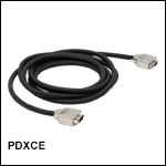
The PDXCE Extension Cable provides 3000.0 mm (118.11") of extra length when connecting the controller to an ORIC stage with a D-Sub connector.
| Item # | PDXC | PDXC2 | |
|---|---|---|---|
| Performance Specificationsa | |||
| SMC Port | Number of Ports | Two | None |
| Voltage | 0 to 40 V | - | |
| Frequency | 20 kHz Max | - | |
| D-Sub Port | Number of Ports | One | |
| Voltage | -10 to 50 V | 0 to 56 V | |
| Frequency | 20 kHz Max | ||
| Max Current Limit | 10 A | ||
| Front USB | Type A, USB HID Host | ||
| Back USB | Type B, USB Device 2.0 | ||
| I/O Port | Voltage of Analog In/Out | -10 to 10 V, ±2% | |
| Voltage of Trigger In/Out | 0 to 5 V, TTL | ||
| Daisy Chain Ports | Two RJ-45 Ports | None | |
| Ethernet PC Communication | None | One RJ-45 Port | |
| Dimensions (L x W x H) | 314.2 mm x 150.0 mm x 84.3 mm (12.37” x 5.91” x 3.32”) |
115.2 mm x 150.0 mm x 48.5 mm (4.54” x 5.91” x 1.91”) |
|
| Weight | 5 kg | 0.53 kg | |
| Operating Temperature | 10 - 35 °C | ||
| Input Power | 100 - 240 VAC, 50 - 60 Hz | 12 V, 3 A DAC | |
| Compatible Stages | PDXZ1(/M), PD2(/M), PDX2(/M), PDX4(/M), PDX1(/M), PDX1A(/M), PDX1AV(/M), PD1(/M)b,c, PD1V(/M)b,c, PD1D(/M)b,c,d, PD3(/M)b, PDX3(/M), PDR1C(/M)b,c, PDXR1(/M) |
||
Click to Enlarge
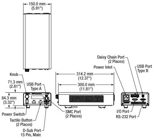
Figure 2.1 PDXC Controller Mechanical Drawing. Please see the Pin Diagrams tab for more information.
Click to Enlarge
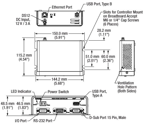
Figure 2.2 PDXC2 Compact Controller Mechanical Drawing. Please see the Pin Diagrams tab for more information.
PDXC Front Panel
15-Pin D-Sub
For PDX1(/M), PDX1A(/M), PDX1AV(/M), PD2(/M), and PD3(/M) Stages
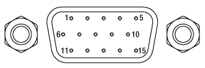
For open- and closed-loop operations, with a resolution up to 10 nm and speed up to 20 mm/s.
| Pin(s) | Voltage Range | Name | Description |
|---|---|---|---|
| 1 | -7.5 to +12.5 V | Encoder_B_N | Encoder B- |
| 2 | -7.5 to +12.5 V | Encoder_B_P | Encoder B+ |
| 3 | 0 V | GND | Digital Ground |
| 4 | -7.5 to +12.5 V | Encoder_A_N | Encoder A- |
| 5 | -7.5 to +12.5 V | Encoder_A_P | Encoder A+ |
| 6,7 | - | - | Reserved |
| 8 | +5 V | +5 V | 5 V Power |
| 9 | -7.5 to +12.5 V | Encoder_Z_N | Encoder Z- |
| 10 | -7.5 to +12.5 V | Encoder_Z_P | Encoder Z+ |
| 11 | -10 to +50 V | SigOut2 | Piezo Output 2 |
| 12 | 0 V | PGND | Power Ground |
| 13 | -10 to +50 V | SigOut1 | Piezo Output 1 |
| 14 | 5 V TTL | EEPROM | 1-Wire EEPROM |
| 15 | - | - | Reserved |
CH1 & CH2
SMC Male
For PD1(/M), PD1D(/M), and PDR1(/M) Stages

0 to 40 V
The SMC ports can be used to control open-loop PD1 and PDR1 series stages.
USB (Type A)

Connects a general HID mouse to control the stage movement by scrolling the wheel back and forth. When the device is set in open-loop operation, it will move a set number of pulses with each scroll, while in closed-loop operation it will move at a set step distance with each scroll.
PDXC Back Panel
Two RJ-45 Ports
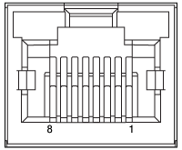
Connects to another PDXC device either using the IN or OUT port with the included ethernet cable. Up to 12 devices can be connected in series.
I/O Port
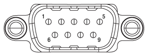
An I/O cable is provided to breakout the Trigger In, Trigger Out, Analog In, and Analog Out pins to BNCs on included cable.
| Pin | Voltage Range | Name | Description |
|---|---|---|---|
| 1 | 5 V TTL | Ext_Sync_p | Daisy-Chain Clock |
| 2 | 5 V TTL | Ext_Sync_n | Daisy-Chain Clock |
| 3 | - | N.C. | Not Connected |
| 4 | 0 V | GND | Ground Pin |
| 5 | 0 V | GND | Ground Pin |
| 6 | - | N.C. | Not Connected |
| 7 | -10 to +10 V | RS_485_p | Positive Differential Signal of Daisy-Chain |
| 8 | -10 to +10 V | RS_485_n | Negative Differential Signal of Daisy-Chain |
| Pin | Voltage Range | Name | Description |
|---|---|---|---|
| 1 | - | - | Reserved |
| 2 | 0 V | GND | Ground Pin |
| 3 | 0 to 5 V | Trigger In | Trigger to Update New Target Position |
| 4 | 0 V | GND | Ground Pin |
| 5 | -10 to +10 V | Analog In | Input as New Target Position |
| 6 | - | - | Reserved |
| 7 | 0 V | GND | Ground Pin |
| 8 | 0 to 5 V | Trigger Out | Trigger When Actual Position is on Target |
| 9 | -10 to +10 V | Analog Out | Output to Reflect the Actual Position |
Computer Connections
USB (Type B)

The USB port connects to a computer for software or command-line control.
RS-232
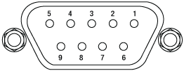
Connects to a computer for command-line control.
| Pin(s) | Voltage Range | Name | Description |
|---|---|---|---|
| 1 | - | N.C. | Not Connected |
| 2 | -15 to +15 V | TXD | Transmits Data |
| 3 | -15 to +15 V | RXD | Receives Data |
| 4 | - | N.C. | Not Connected |
| 5 | 0 V | GND | Ground Pin |
| 6,7,8,9 | - | N.C. | Not Connected |
PDXC2 Front Panel
15-Pin D-Sub
For PDX1(/M), PDX1A(/M), PDX1AV(/M), PD2(/M), and PD3(/M) Stages

For open- and closed-loop operations, with a resolution up to 10 nm and speed up to 20 mm/s.
| Pin(s) | Voltage Range | Name | Description |
|---|---|---|---|
| 1 | -7.5 to +12.5 V | Encoder_B_N | Encoder B- |
| 2 | -7.5 to +12.5 V | Encoder_B_P | Encoder B+ |
| 3 | 0 V | GND | Digital Ground |
| 4 | -7.5 to +12.5 V | Encoder_A_N | Encoder A- |
| 5 | -7.5 to +12.5 V | Encoder_A_P | Encoder A+ |
| 6,7 | - | - | Reserved |
| 8 | +5 V | +5 V | 5 V Power |
| 9 | -7.5 to +12.5 V | Encoder_Z_N | Encoder Z- |
| 10 | -7.5 to +12.5 V | Encoder_Z_P | Encoder Z+ |
| 11 | -10 to +50 V | SigOut2 | Piezo Output 2 |
| 12 | 0 V | PGND | Power Ground |
| 13 | -10 to +50 V | SigOut1 | Piezo Output 1 |
| 14 | 5 V TTL | EEPROM | 1-Wire EEPROM |
| 15 | - | - | Reserved |
I/O Port

An I/O cable is provided to breakout the Trigger In, Trigger Out, Analog In, and Analog Out pins to BNCs on included cable.
| Pin | Voltage Range | Name | Description |
|---|---|---|---|
| 1 | - | - | Reserved |
| 2 | 0 V | GND | Ground Pin |
| 3 | 0 to 5 V | Trigger In | Trigger to Update New Target Position |
| 4 | 0 V | GND | Ground Pin |
| 5 | -10 to +10 V | Analog In | Input as New Target Position |
| 6 | - | - | Reserved |
| 7 | 0 V | GND | Ground Pin |
| 8 | 0 to 5 V | Trigger Out | Trigger When Actual Position is on Target |
| 9 | -10 to +10 V | Analog Out | Output to Reflect the Actual Position |
RS-232

Connects to a computer for command-line control.
| Pin(s) | Voltage Range | Name | Description |
|---|---|---|---|
| 1 | - | N.C. | Not Connected |
| 2 | -15 to +15 V | TXD | Transmits Data |
| 3 | -15 to +15 V | RXD | Receives Data |
| 4 | - | N.C. | Not Connected |
| 5 | 0 V | GND | Ground Pin |
| 6,7,8,9 | - | N.C. | Not Connected |
USB (Type A)

Connects the HID MCMK3 joystick to control the stage movement by scrolling the wheel back and forth. When the device is set in open-loop operation, it will move a set number of pulses with each scroll, while in closed-loop operation it will move at a set step distance with each scroll.
PDXC2 Back Panel
RJ-45 Port

Connects the PDXC2 device to the router/switch for software control with a networked PC.
USB (Type B)

The USB port connects to a computer for software or command-line control.
Software
PDXC Version 2.2.1
The PDXC Software Package, which includes a GUI, drivers, and LabVIEW™/C++/Python SDK for third-party development.
Thorlabs offers the PDXC software package to interface with the PDXC Piezo Stage Controller. This controller is designed to drive the following piezo inertia stages:
- PDXZ1(/M) 4.5 mm Vertical Stage with Optical Encoder
- PD2(/M) 5 mm Linear Stage
- PDX2(/M) 5 mm Linear Stage with Optical Encoder
- PDX4(/M) 12 mm Linear Stage with Optical Encoder
- PD1(/M) 20 mm Linear Stage
- PD1V(/M) Vacuum-Compatible 20 mm Linear Stage
- PD1D(/M) 20 mm Monolithic XY Stage
- PDX1(/M) 20 mm Linear Stage with Optical Encoder
- PDX1A(/M) 20 mm Low-Profile, Linear Stage with Optical Encoder
- PDX1AV(/M) Vacuum-Compatible 20 mm Low-Profile, Linear Stage with Optical Encoder
- PD3(/M) 50 mm Linear Stage
- PDX3(/M) 50 mm Linear Stage with Optical Encoder
- PDR1C(/M) Rotation Stage
- PDXR1(/M) Rotation Stage with Optical Encoder
The software package allows two methods of usage: graphical user interface (GUI) utilities for direct interaction with and control of the controllers 'out of the box', and a set of programming interfaces for third-party development of custom-integrated positioning and alignment solutions to be easily programmed in the development language of choice (LabVIEW™/C++/Python SDK).
Software
Kinesis Version 1.14.53
The Kinesis Software Package, which includes a GUI for control of Thorlabs' Kinesis system controllers.
Also Available:
- Communications Protocol

Figure 58A Kinesis GUI Screen
Thorlabs offers the Kinesis® software package to drive our wide range of motion controllers. The software can be used to control devices in the Kinesis family, which covers a wide variety of motion controllers ranging from small, low-powered, single-channel drivers (such as the K-Cubes®) to high-power, multi-channel benchtop units and modular 19" rack nanopositioning systems (the MMR60x Rack System).
The Kinesis Software features .NET controls which can be used by 3rd party developers working in the latest C#, Visual Basic, LabVIEW™, or any .NET compatible languages to create custom applications. Low-level DLL libraries are included for applications not expected to use the .NET framework and APIs are included with each install. A Central Sequence Manager supports integration and synchronization of all Thorlabs motion control hardware.
By providing this common software platform, Thorlabs has ensured that users can mix and match any of our motion control devices in a single application, while only having to learn a single set of software tools. In this way, it is perfectly feasible to combine any of the controllers from single-axis to multi-axis systems and control all from a single, PC-based unified software interface.
The software package allows two methods of usage: graphical user interface (GUI) utilities for direct interaction with and control of the controllers 'out of the box', and a set of programming interfaces that allow custom-integrated positioning and alignment solutions to be easily programmed in the development language of choice.
The following accessories are included with each PDXC Controller:
- 2 m Ethernet Cable, Male Cat5e Connector to Male Cat5e Connector
- 0.5 m I/O Cable, Female 9-Pin D-Sub Connector to 4 Male BNC Connectors
- 2 m USB Cable, Male Type A Connector to Male Type B Connector
- 1.5 m Power Supply Cable (Region Specific), Male NEMA 5-15-P Connector to Female IEC 320 C13/C14 Connector
The following accessories are included with each PDXC2 Controller:
- 2 m Ethernet Cable, Male Cat5e Connector to Male Cat5e Connector
- 0.5 m I/O Cable, Female 9-Pin D-Sub Connector to 4 Male BNC Connectors
- 2 m USB Cable, Male Type A Connector to Male Type B Connector
- 1.5 m Power Supply Cable (Region Specific), Male NEMA 5-15-P Connector to Female IEC 320 C13/C14 Connector
- 1.23 m, M8, 4-pin female connector, input range 100 - 240 VAC, 12 VDC output
| Posted Comments: | |
ハンユ チュオ
(posted 2025-01-14 12:38:39.12) お世話になっております。私は現在、コントローラPDXC2と回転ステージPDXR1/Mを所有しております。現在、新たに直線移動ステージ(例:PDX1/MまたはPDX1A/M)の購入を検討しています。しかし、PDXC2にはステージ用のインターフェースが一つしかないように見受けられます。
そのため、PDXC2を用いて回転ステージと直線移動ステージの2つを同時に制御することが可能かご確認いただけますでしょうか?もし不可能な場合、何か経済的な解決方法がございましたら、ご教示いただけると幸いです。
お忙しいところ恐れ入りますが、どうぞよろしくお願いいたします。 cdolbashian
(posted 2025-01-29 09:53:31.0) Thank you for contacting Thorlabs. PDXC2 is a single stage ORIC® piezo inertia stage controller and currently it is recommended to use two PDXC2 for your application.The three-channel controller is currently under development, please contact your local tech support team (techsupport.jp@thorlabs.com) for further information if you're interested. ZIYE YIN
(posted 2024-07-12 10:14:27.147) Hi,
When I connected the controller to PC and a piezo stage, then opening the Kinesis software, I cannot choose closed loop at all. The characters are gray. Do you have any idea about why that happened? Braulio Antonio
(posted 2023-09-28 13:03:09.427) Hi
I was wondering if I can use the GUI or Python to set up a piezo linear stage into an oscillating mode (moving a 1 mm distance back and forth at a set frequency). cdolbashian
(posted 2023-10-19 03:24:34.0) hank you for contacting Thorlabs. The piezo linear stages could achieve moving back and forth between two positions through PDXC GUI's external trigger mode function or Python programing. But the “oscillating” frequency would be limited by what stage you are using and the maximum speed of stage. We will contact you directly to discuss this further. 晓龙 朱
(posted 2023-06-04 21:56:38.76) Dear Team,
Is that possible to use matlab to control the PDXC stages?
Thanks
BR
Xiaolong cdolbashian
(posted 2023-06-12 08:30:16.0) Thank you for contacting Thorlabs. We provide C++ SDK in PDXC software package, which you may use to write your own Matlab wrapper. Marek Subernat
(posted 2023-01-03 15:53:58.937) I am using this product with the PD2 stages. It would be super helpful if one PDXC could control 2 PD2 stages. I see two possible ways to accomplish this: making the SMC connectors compatible with PD2 and not just PD1 stages (increasing the driving voltage), or selling a harness that combines two DSUB connectors from the PD2 stages into a single DSUB input to the PDXC. There are only 4 used wires on a PD2 DSUB connector - power ground, digital ground, 1-wire EEPROM, and SigOut1. The PDXC DSUB has 2 SigOut outputs (pins 11 & 13) and can therefore drive two stages. The power ground and digital ground could be shared between the stages. The only modification to the PDXC would need to be an additional 1-wire EEPROM. There are currently 3 reserved pins on the PDXC DSUB making this possible. If the additional EEPROM pin would prove too much of a change in the product, this could also be addressed in software: if you could forgo the need for EEPROM, one could still drive two stages with one DSUB connector using the suggested alternative harness. I understand this product is meant to serve multiple motion stages with different parameters, but with an additional relatively simple harness and some minor modifications to currently unused pins, the flexibility could be further expanded. cdolbashian
(posted 2023-01-10 03:13:15.0) Thank you for the great customer inspired new product idea. I agree that these would make an excellent addition to our product line and will make the recommendations to our business unit leaders for future consideration as a future product. JIAQI LI
(posted 2022-08-03 08:51:56.01) Hello,
we bought the PDX1/M and the PDXC controller from your company. Now I downloaded all the documents from the internet including PDXC software and the firmware program. However, when I tried to connect the controller with the software, the software could not read it. I guess i did something incorrectly. could you send me the software installation instruction as well as the product guidance?
waiting for your reply.
Thanks
Jiaqi cdolbashian
(posted 2022-08-05 04:38:23.0) Thank you for contacting Thorlabs. We will reach out to you directly via email to help troubleshoot. For future troubleshooting issues, please contact our tech support team: Techsupport@thorlabs.com |

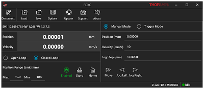
Figure G1.1 Software Package Provides GUI, Drivers, and Third-Party Programming Support
- Controller for ORIC Piezo Inertia Linear Stages, PDXZ1(/M) Vertical Stage, and both PDR1C(/M) and PDXR1(/M) Rotation Stages
- Supports Both Open- and Closed-Loop Operation
- Modular Linear Amplifier Paired with High-Power Power Supply Outputs Peak Current of 10 A
- Supports Daisy-Chain Mode where Several Controllers Work Together to Simultaneously Control Multiple Stages
- SMC and 15-Pin D-Sub Ports Available
This controller is designed to control our ORIC piezo-inertia-driven linear stages, PDXZ1(/M) vertical stage, and both PDR1C(/M) and PDXR1(/M) rotation stages. It offers two channels that support open-loop stage control using SMC outputs and one channel that can provide open- or closed-loop stage control using a 15-pin D-sub output.
Embedded software allows this unit to be fully controlled using the buttons, LCD display, and knob on the front panel. Alternatively, built-in external trigger modes support single-channel operation. By connecting multiple controllers together, multi-channel operation in D-sub mode, useful for applications like raster scans that require more than one direction of motion, is possible. Users can select the output port(s), switch between open-loop and closed-loop modes, and perform homing and encoder calibration without being connected to a PC. In addition to these on-unit controls, USB connectivity and the PDXC software (available for download on the PDXC Software tab) support remote control via a PC (GUI shown in Figure G1.1). Daisy-chain mode, which allows multiple controllers to move multiple stages at very low delay, is also possible with a USB connection to a PC; this can be activated by connecting multiple controllers with RJ-45 cables between them.
The unit comes with a compatible region-specific power cord. For all applications, use an IEC320 compatible power cord fitted with a plug appropriate for your particular power socket. Ensure the line voltage rating marked on the rear panel agrees with your local power supply.

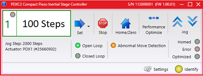
Figure G2.1 Kinesis GUI Screen for PDXC2
- Controller for ORIC Piezo Inertia Linear Stages, PDXZ1(/M) Vertical Stage, and both PDR1C(/M) and PDXR1(/M) Rotation Stages
- Compact Design (L x W x H: 115.2 mm x 150.0 mm x 48.5 mm)
- Supports Both Open- and Closed-Loop Operation
- Energy Efficient Switch Amplifier Circuit Outputs Peak Current of 10 A
- Configurable High Speed Communication Interfaces: USB 2.0, Gigabit Ethernet, Digital I/0, Analog I/0
- 800 Hz to 20 kHz Pulse Rate
The PDXC2 compact controller is designed for our ORIC piezo-inertia-driven linear stages, PDXZ1(/M) vertical stage, and both PDR1C(/M) and PDXR1(/M) rotation stages. It features one channel that supports open- or closed-loop stage control using a 15-pin D-sub output. The PDXC2AD D-sub to SMC adapter cable (sold below) can be used to operate stages with an SMC connection in open-loop mode.
All the operating parameters and operations are controlled by PC with the Kinesis® software (available for download on the Kinesis Software tab). The PDXC2 controller is connected to PC through either the USB or ethernet ports on the back panel of the controller, see the Pin Diagrams tab for details. The Kinesis GUI, shown in Figure G2.1, displays the basic commands for stage control including switching between open- and closed-loop modes, performing homing operation, and parameter optimization. Calibration for specific ORIC stages with encoders (Item #s PDX1(/M), PDX1A(/M), PDX1AV(/M), and PDXR1(/M) only) is performed with the PDXC2 Calibration Tool found on the Motion Control Software page. Trigger modes and movement parameters can be accessed in the settings panel on the bottom right of the GUI, where operations such as raster scanning can be configured; please see the user manual for details. Command-line control is also possible through the USB and RS-232 ports.
The PDXC2 unit is powered by the included DS12 12 VDC power adapter which operates at an input voltage of 100 - 240 VAC and ships with a region-specific AC cable. For all applications, use an IEC320 compatible power cord fitted with a plug appropriate for your particular power socket. Make sure that the line voltage rating marked on the power adapter agrees with your local power supply.

- Utilizes Standard USB HID Protocol
- Knobs Provide Hand-Operated Control for up to Three Axes
- Top-Located Speed Dial for Sensitivity Adjustment
- Compatible with Daisy-Chain Mode to Control Main and Secondary Stages Simultaneously (Item # PDXC Only)
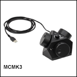
The MCMK3 Joystick is a hand-operated, 3-knob box with an attached USB cable. Each of the three side faces of the joystick include a rotating knob and a push-button LED switch. When used in conjunction with the PDXC controller, the knob and button on each side are dedicated to a single channel; the knob is responsible for movement of the stage, while the button enables and disables the channel to preserve a position or prevent accidental movements. The push-button will be lit in green when the channel is enabled. A smaller knob on the top face adjusts the velocity output of the larger side knobs, allowing for control of the amount of translation per rotation of each side knob. When the HID Joystick is connected to the USB connector on the front panel of the PDXC2 controller, the user can control the stages with the joystick in open or closed loop mode. The move speed and step size can also be set by adjusting the jog parameters in the settings panel of the Kinesis GUI.
The MCMK3 joystick is a USB HID device and is powered through the USB cable. To control stage movement, the joystick can be plugged into the USB port on the front of the PDXC or PDXC2 Stage Controllers. In D-sub mode on the PDXC controller, the controls will be limited to channel 1; in SMC mode, channels 1 and 2 will control axes 1 and 2 respectively, with relationship between the knob channels and the stage axes remaining fixed. The joystick can also be operated when the PDXC controller is in daisy-chain mode by connecting it to the USB port on the main device. Two other secondary PDXC controllers can be controlled in this fashion by one MCMK3 joystick. For more information about joystick operation in daisy-chain mode, please see the PDXC stage controller manual by clicking on the red Docs icon (![]() ) next to the controller Item # above. In order to use this feature, both version 1.28 or later of the PDXC Firmware and version 1.41 or later of the PDXC Software are required; see the PDXC Software tab to download the latest software for the PDXC stage controller. Support for the use of the MCMK3 joystick with a single PDXC controller when not in daisy-chain mode requires version 1.27 or later of the PDXC Firmware.
) next to the controller Item # above. In order to use this feature, both version 1.28 or later of the PDXC Firmware and version 1.41 or later of the PDXC Software are required; see the PDXC Software tab to download the latest software for the PDXC stage controller. Support for the use of the MCMK3 joystick with a single PDXC controller when not in daisy-chain mode requires version 1.27 or later of the PDXC Firmware.
The MCMK3 joystick can be used with any device that uses the HID class; for more information, see the complete web presentation. For a test utility to aid in troubleshooting and testing the HID reporting of the joystick, see the USB HID Joystick Software page.

Click for Details
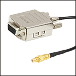
Figure 758B DB15 Female to SMC Male

Click for Details
Figure 758A Mechanical Drawing
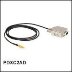
- 1 m Long D-Sub to SMC Adapter Cable
- Connects the PDXC2 Controller's D-sub port to the PD1(/M), PD1V(/M), PD1D(/M), or PDR1C(/M) Stage's SMC Connection
The PDXC2AD adapter cable has a female 15 pin D-sub connection and a male SMC connection. The cable adapts the PDXC2 controller's male 15-pin D-sub port to the SMC termination of the PD1(/M), PD1D(/M), PD1V(/M) 20 mm stages, or PDR1C(/M).

Click to Enlarge
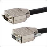
Figure 759B DB15 Male to DB15 Female
Click to Enlarge
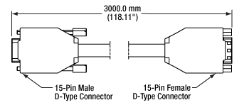
Figure 759A Mechanical Drawing
- Connects Female D-Sub Connector on a PDXZ1(/M), PD2(/M), PDX2(/M), PDX4(/M), PDX1(/M), PDX1A(/M), PDX1AV(/M), PD3(/M), PDX3(/M), or PDXR1(/M) Stage to PDXC or PDXC2 Piezo Inertia Stage Controller
- 3000.0 mm (118.11") of Extra Length
The PDXCE extension cable provides 3000.0 mm (118.11") of extra cord length, if needed, when connecting ORIC stages with a Female D-Sub Connector to the PDXC or PDXC2 ORIC Inertia Stage Controllers. Due to the capacitance of the cables, each stage has a recommended maximum cable length. Please check individual stage specifications before adding extension cables.
 Products Home




 Zoom
Zoom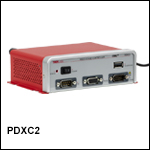
 ORIC Piezo Inertia Stage Controllers