 Products Home
Calibrated Thermal Position & Power Sensors
- Thermal Sensors for Beam Position Detection
- Calibrated Output when Used with a Compatible Thorlabs Console
- Options for Powers from 0.5 mW to 50 W
- Broadband Operation from the UV to IR
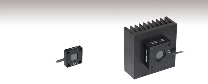
S440C
0.5 mW - 5 W,
30 mm Cage System Compatible
S442C
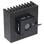
10 mW - 50 W,
Attached Heat Sink


Please Wait
| Key Specificationsa | ||
|---|---|---|
| Item # | S440C | S442C |
| Detector Type | Thermopile in Quadrant Configuration | |
| Wavelength Range | 190 nm - 20 µm | |
| Optical Power Range | 0.5 mW - 5 W | 10 mW - 50 W |
| Power Resolution | 50 µW | 1 mW |
| Position Resolution | 5 µm | 10 µm |
| Housing Features | Through Holes for 30 mm Cage System | Internal SM1 Threading, Heat Sink |
| Connector | D-Sub 9 Pin Male (C Series) | |
| Power Meter Selection Guide |
|---|
| Sensors |
| Photodiode Power Sensors |
| Thermal Power Sensors |
| Thermal Position & Power Sensors |
| Pyroelectric Energy Sensors |
| Power Meter Consoles and Interfaces |
| Digital Handheld Console |
| Analog Handheld Console |
| Touchscreen Handheld Console |
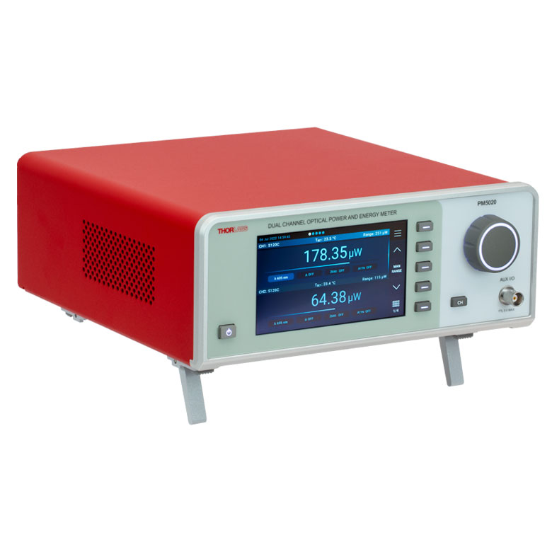
| Dual-Channel Benchtop Console |
| USB Interfaces with External Readout |
| Complete Power Meters |
| Power Meter Bundles |
| Wireless Power Meters with Sensors |
| Compact USB Power Meters |
| Field Power Meters for Terminated Fibers |
Click to Enlarge
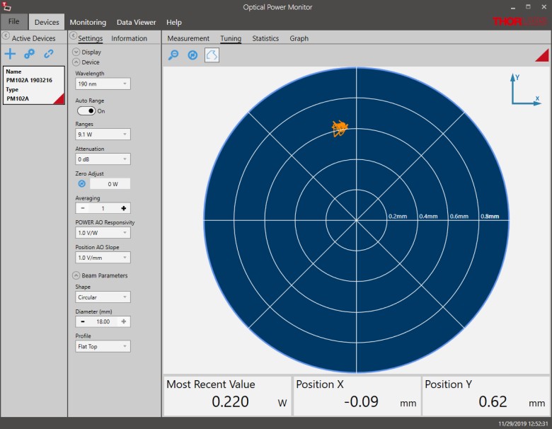
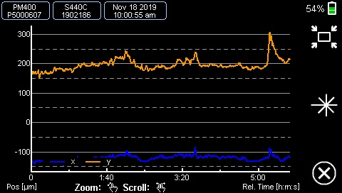
Figure 1.1 Position Tuning Mode in the OPM Software GUI
Features
- Segmented Quadrant Position Sensors
- Broad Wavelength Range with Relatively Flat Spectral Response (See Plot on Specs Tab)
- Wide Optical Power Ranges with High Precision
- C-Series Connector
- Enables Quick Sensor Connection to PM400 Console, PM5020 Console, or PM102 Series Interfaces
- Embedded EEPROM Contains Sensor and Calibration Data
- Post Mountable via 8-32 / M4 Universal Taps
These position sensors use thermopile sensor elements to obtain high-resolution measurements of a beam's position and power. They incorporate our OEM thermal position detectors, which consist of four sensor quadrants that calculate the beam's position by comparing the intensity measured in each quadrant. See the Operation tab for details.
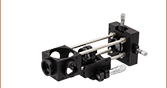
The S440C detector uses the TD4HR18XP PCB-mounted thermopile sensor and is optimized for high sensitivity. The housing features four Ø6 mm through holes for compatibility with 30 mm cage systems, as well as an 8-32 / M4 universal tap for post mounting. The S442C detector incorporates the TD4HP18XA aluminum-plate-mounted thermopile sensor and can measure power levels up to 50 W. The housing includes a heat sink for superior heat dissipation, as well as two 8-32 / M4 universal taps for post mounting.
We also offer thermal sensor heads for a wide range of applications, as well as photodiode-based position sensing detectors, which offer faster response times that make them suitable for automated alignment.
For information on recalibration services for these products, please contact Tech Support.
Compatible Power Meter Console and Power Meter Interfaces
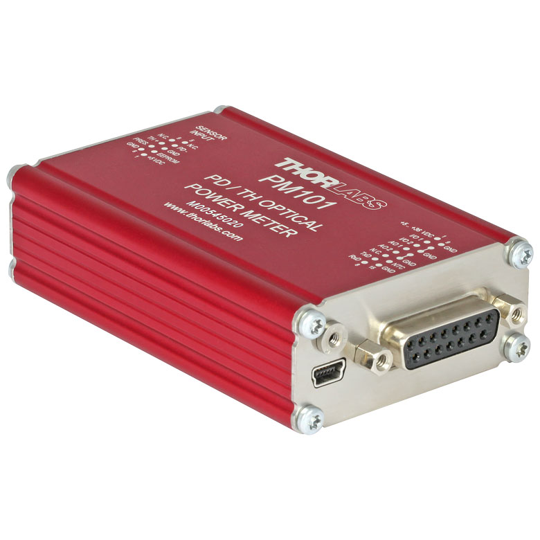
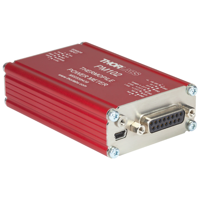
Both detectors feature C-Series connectors and can be controlled using either the PM400 or PM5020 power meter console or the PM102 series power meter interfaces (all control units sold separately). The PM400 console features a touchscreen display for the power and position readout. The PM5020 benchtop console can read the power and position of up to two sensors and display it on the touchscreen or on a PC using its remote capabilities. The PM102 series requires a PC with the OPM software in order to operate the sensor in a power meter system; depending on the PM102 model used, operation can be through USB 2.0, RS-232, or UART.
There are a number of different display options that can be viewed either on the PM400 or PM5020 console display screen or in the OPM software GUI:
- Position Tuning: a visual representation of the beam's location on the sensor. The visible area can be adjusted between a centered Ø1 mm circle and Ø6 mm circle. The left side shows the power measured by the entire sensor surface and the X and Y coordinates of the beam. An optional setting can show a visual trace of the position over time (Position Trace Display).
- Graph: a graph of the X and Y positions over time, or a graph of total power over time. The user can touch a single button to toggle between the position and power graphs.
- Statistics: a table of measurement statistics. The unit takes a number of sequential samples and then displays the mean, median, standard deviation, and more.
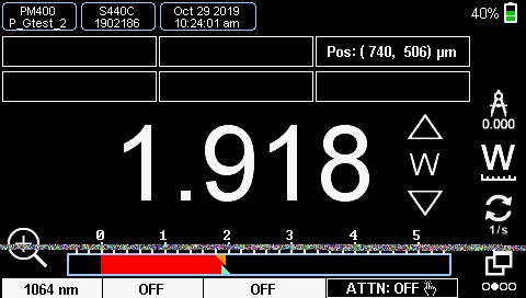
- Numerical: a digital readout of the overall power measurement for the entire sensor, displayed in W, V, or dB. The beam position coordinates are also shown in the upper right of the screen.
See the PM400 full web presentation and manual for more information on the touchscreen power meter console and the PM5020 full web presentation and manual for more information on the dual-channel benchtop power meter console. See the PM102 series full web presentation and manual for details on the power meter interfaces.

Click to Enlarge
Click Here for Raw Data
The wavelength range of the data in this graph is limited by the detector used during testing. The thermal position detectors are capable of operating at up to 20 µm.
| Item # | S440C | S442C |
|---|---|---|
| Wavelength Range | 190 nm - 20 µm | |
| Optical Power Working Range | 0.5 mW - 5 W | 10 mW - 50 W |
| Max Average Power Densitya | 1.5 kW/cm2 | |
| Max Pulse Energy | 0.3 J/cm2 (1 ns Pulse) 5 J/cm2 (1 ms Pulse) |
|
| Power Resolutionb | 50 µW | 1 mW |
| Linearity | ±1% | |
| Measurement Uncertaintyc | ±5% at 1064 nm; ±7% for 250 nm - 17 µm |
|
| Position Resolution | 5 µm | 10 µm |
| Position Accuracyd | 50 µm (1 mm Circle); 200 µm (6 mm Circle) | 100 µm (1 mm Circle); 300 µm (6 mm Circle) |
| Position Repeatabilityd | 15 µm (1 mm Circle); 100 µm (6 mm Circle) | 25 µm (1 mm Circle); 150 µm (6 mm Circle) |
| Response Timee | <1.1 s | <0.6 s |
| Coating / Diffuser | High Power Broadband | |
| Cooling | Convection | |
| Head Temperature Measurement | Thermistor (NTC) | |
| Input Aperture | 17 mm x 17 mm | Ø17.5 mm |
| Sensor Dimensions | 40.6 mm x 40.6 mm x 8.9 mm (1.60" x 1.60" x 0.35") |
100.0 m x 100.0 mm x 57.8 mm (3.94" x 3.94" x 2.28") |
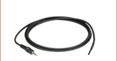
| Cable Length | 1.5 m | |
| Connector | D-Sub-9 Pin Male | |
| Weight | 0.2 kg | 0.75 kg |
| Mounting Options | 8-32 / M4 Universal Tap, 30 mm Cage Rod Through Holes |
Two 8-32 / M4 Universal Taps, SM1 (1.035"-40) Internal Thread, Externally Threaded SM1 Coupler Included |
| Compatible Console | PM400, and PM5020 | |
| Compatible Interfaces | PM102, PM102A, and PM102U | |
For details on sensor-related terminology, see our list of definitions.
Click to Enlarge
Figure 3.1 A thermal sensor with axially configured thermocouples, which is depicted as seen from the side. Light is incident on the top, and heat flows down through the thermocouple layer and dissipates in the heat sink below.
Operating Principle
These thermal power detectors are based on thermopile sensors. The top layer of the sensor, which appears gray in color, consists of a light-absorbing material. Located immediately behind the sensor, and in thermal contact with it, is a layer containing multiple thermocouples. Thermocouples are made by bringing two dissimilar metals into contact, and their point of contact is called a junction. The other side of the thermocouple layer must be thermally coupled to a heat sink. The thermocouples are connected in series, and the placement of the junctions alternates from being in close proximity to the absorber to being in close proximity to the heat sink. This axial (or matrix) configuration of thermocouples is diagrammed in Figure 3.1.
The absorber converts incident light energy into heat. The heat flows from the absorber, across the thermocouples, and to the heat sink, where it dissipates. The temperatures of the thermocouple junctions placed close to the absorber are higher than the adjacent junctions placed close to the heat sink. This arrangement takes advantage of the thermoelectric (Seebeck) effect, in which a temperature difference between adjacent junctions generates a proportional voltage difference. By connecting multiple thermocouples in series, the magnitude of the generated voltage is increased.
Axially-configured sensors such as the thermal quadrant detectors on this page can achieve high resolutions in the microwatt range while providing relatively fast response times. These sensors detect optical powers up to 50 Watts, which is limited mostly by the thickness of the absorbing material.

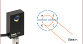
Figure 3.2 The sensor area consists of four thermopile sensors arranged as quadrants of a square.
Quadrant Detector Beam Position Calculation
Each thermal position detector consists of four individual thermopile sensors arranged in a 2 x 2 matrix, as shown in Figure 3.2. The quadrants are mechanically coupled by one aluminum plate but electrically isolated; thus, heat is free to flow across the entire active area, but the signal from each quadrant measures the response in only that quadrant's thermopile. The beam's coordinates X and Y are calculated using the voltage outputs of all four detectors:
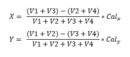
where V1, V2, V3, and V4 are the output voltage signals from Q1, Q2, Q3, and Q4, respectively, in Figure 3.2. Since the sensor response is nonlinear, the detector uses a calibration factor for each axis, Calx and Caly, to calculate the absolute position.
Click to Enlarge
Figure 3.3 Natural Response of the S440C and S442C Detectors. The dotted line is at 0.99 and the red square indicates the point on the curve corresponding to a single sensor time constant.
Natural Responses, the Sensor Time Constant, and Power Measurement Predictions
The typical natural response of a thermal sensor is its measured response to being instantaneously and steadily illuminated after being held in total darkness. This step function illumination stimulus produces a measured response that can be modeled using an exponential function and is similar to the function describing the rate at which a capacitor charges. Figure 3.3 shows the natural response measured for the thermal position sensing detectors.
The sensor time constant is defined in terms of how long it takes for the sensor response to reach 99% of its maximum response. The definition used by Thorlabs' power meter consoles is that when the sensor has reached the 99% level, a time period equal to five sensor time constants has elapsed. In Figure 3.3, the dotted line corresponds to the 99% level and the red square to the response after a single sensor time constant has elapsed. When the sensor's natural response characteristic function is known, it is possible to use it to model and predict the final power reading well before the sensor reading has stabilized.
Protect Thermal Power Sensors from Thermal Disturbances
For the most accurate results, thermal power sensors should be protected from air flow and other thermal disturbances during operation. Otherwise, measurements will drift. This is of particular importance for low power sensors with high resolution. Handheld use is not recommended for any of the thermal power sensors, as body heat transferred to the sensor or heat sink can negatively impact the accuracy of the measurements.
C-Series Sensor Connector
D-Sub-9 Pin Male
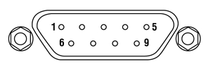
| Pin | Connection |
|---|---|
| 1 | Not Used |
| 2 | EEPROM Signal |
| 3 | Sensor Ground |
| 4 | TH3 |
| 5 | TH4 |
| 6 | EEPROM Ground |
| 7 | NTC |
| 8 | TH1 |
| 9 | TH2 |
Thorlabs offers a wide selection of power and energy meter consoles and interfaces for operating our power and energy sensors. Key specifications of all of our power meter consoles and interfaces are presented in this tab to help you decide which device is best for your application. We also offer self-contained wireless power meters and compact USB power meters.
When used with our C-series sensors, Thorlabs' power meter consoles and interfaces recognize the type of connected sensor and measure the current or voltage as appropriate. Our C-series sensors have responsivity calibration data stored in their connectors. The console will read out the responsivity value for the user-entered wavelength and calculate a power or energy reading.
- Photodiode sensors deliver a current that depends on the input optical power and the wavelength. The current is fed into a transimpedance amplifier, which outputs a voltage proportional to the input current. The photodiode's responsivity is wavelength dependent, so the correct wavelength must be entered into the console for an accurate power reading. The console reads out the responsivity for this wavelength from the connected sensor and calculates the optical power from the measured photocurrent.
- Thermal sensors deliver a voltage proportional to the input optical power. Based on the measured sensor output voltage and the sensor's responsivity, the console will calculate the incident optical power.
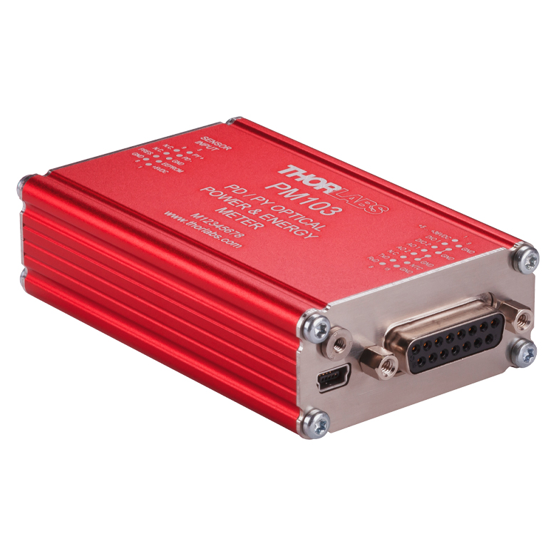
- Energy sensors are based on the pyroelectric effect. They deliver a voltage peak proportional to the pulse energy. If an energy sensor is recognized, the console will use a peak voltage detector and the pulse energy will be calculated from the sensor's responsivity.
The consoles and interfaces are also capable of providing a readout of the current or voltage delivered by the sensor. Select models also feature an analog output.
Consoles
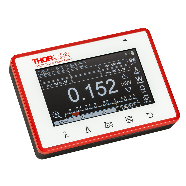
| Item # | PM100A | PM100D | PM400 | PM5020 |
|---|---|---|---|---|
| (Click Photo to Enlarge) | 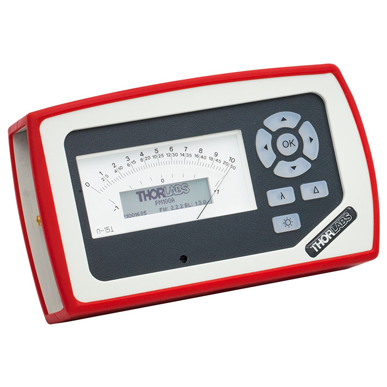 |
 |
 |
 |
| Key Features | Analog Power Measurements | Digital Power and Energy Measurements | Digital Power and Energy Measurements, Touchscreen Control | Dual Channel |
| Compatible Sensors | Photodiode and Thermal Power | Photodiode Power, Thermal Power, and Pyroelectric Energya | Photodiode Power, Thermal Power, Thermal Power and Position, and Pyroelectric Energya | Photodiode Power, Thermal Power, Thermal Power and Position, and Pyroelectric Energy |
| Housing Dimensions (H x W x D) |
7.24" x 4.29" x 1.61" (184 mm x 109 mm x 41 mm) |
7.09" x 4.13" x 1.50" (180 mm x 105 mm x 38 mm) |
5.35" x 3.78" x 1.16" (136.0 mm x 96.0 mm x 29.5 mm) |
9.97" x 4.35" x 11.56" (253.2 mm x 110.6 mm x 293.6 mm) |
| Channels | 1 | 2 | ||
| External Temperature Sensor Input (Sensor not Included) | - | - | Readout and Record Temperature Over Time | Readout and Record Temperature Over Time |
| External Humidity Sensor Input (Sensor not Included) | - | - | Readout and Record Humidity Over Time | Readout and Record Humidity Over Time |
| Input/Output Ports | - | 4 GPIO, Programmable | 4 Configurable Digital I/O Channels | |
| Shutter Control | - | - | - | Support for SH05R(/M) or SH1(/M) Optical Shutter with Interlock Input |
| Fan Control | - | - | - | |
| Source Spectral Correction | - | - | ||
| Attenuation Correction | - | - | ||
| External Trigger Input | - | - | - | |
| Display | ||||
| Type | Mechanical Needle and LCD Display with Digital Readout | 320 x 240 Pixel Backlit Graphical LCD Display | Protected Capacitive Touchscreen with Color Display | |
| Dimensions | Digital: 1.9" x 0.5" (48.2 mm x 13.2 mm) Analog: 3.54" x 1.65" (90.0 mm x 42.0 mm) |
3.17" x 2.36" (81.4 mm x 61.0 mm) |
3.7" x 2.1" (95 mm x 54 mm) |
4.32" x 2.43" (109.7 mm x 61.6 mm) |
| Refresh Rate | 20 Hz | 10 Hz (Numerical) 25 Hz (Analog Simulation) |
25 Hz | |
| Measurement Viewsb | ||||
| Numerical | ||||
| Mechanical Analog Needle | - | - | - | |
| Simulated Analog Needle | - | |||
| Bar Graph | - | |||
| Trend Graph | - | |||
| Histogram | - | - | - | |
| Statistics | ||||
| Memory | ||||
| Type | - | SD Card | NAND Flash | SD Card |
| Size | - | 2 GB | 4 GB | 8 GB |
| Power | ||||
| Battery | LiPo 3.7 V 1300 mAh | LiPo 3.7 V 2600 mAh | - | |
| External | 5 VDC via USB or Included AC Adapter | 5 VDC via USB | Line Voltage: 100 - 240 V | |


| Posted Comments: | |
Fabian Roeser
(posted 2025-03-26 12:22:20.913) Will there be a USB version (like the PM16-405 etc.)? Alternatively, is there an interface box capable of multiple sensor readout?
We will need 5-10 sensors and would like to omit the interface
regards jjadvani
(posted 2025-03-27 03:46:00.0) Dear Fabian, we do not currently have any plans to introduce a USB version of this sensor. However, I will include this idea in our database for future improvement. We do not have an interface box in which you may connect 5-10 sensors at the same time. You can use several interface boxes, including PM102, PM102A, and PM102U. It is possible to stack them on top of each other using accessories. I'll contact you directly to provide additional assistance Alana Horne
(posted 2025-03-26 11:52:08.863) Hello,
The position resolution for the S440C is given as 5um, however different accuracies are given for different diameters (up to 200um for the 6mm diameter). Can you explain the difference in these specifications? And can you clarify what the circle diameter in these specifications is referring to? jjadvani
(posted 2025-03-27 06:22:46.0) Dear Alana, Thank you for contacting Thorlabs. Resolution refers to the smallest measurable change that the sensor can detect. Accuracy defines how close the measured value is to the actual or true value. circle diameter refers to the physical area on the sensor's surface where the beam is detected. The visible area on the sensor can range in size from a centered Ø1 mm circle to a Ø6 mm circle. I will contact you directly to provide further information. myeong kim
(posted 2024-09-12 12:54:04.87) model : s442c
I want to measure the power stability of a 1550nm 10W fiber laser over time.
How many hours can I measure 10W output?
We want to measure continuously for more than 2 hours. hchow
(posted 2024-09-12 05:15:20.0) Dear Mr. Kim, thank you for your feedback. It is indeed possible to do a long term position measurement using the S442C when paired with a compatible console/interface. I will personally reach out to you to provide more information about the capabilities of the S442C. Thank you. Justin Sayres
(posted 2024-07-07 22:02:31.803) Do you have a lens that can be mounted and be used to determine if the incident beam is centered as well as parallel? jjadvani
(posted 2024-07-08 05:40:41.0) Dear Justin, Thank you for providing feedback. The S440C contains a cage-compatible hole of 30 mm that can be used to mount a cage rod, followed by a standard cage plate and lens. After that, you can use the alignment target to see if the beam is centered. KEVIN WAGNER
(posted 2023-11-09 06:30:00.177) I am interested in this detector for an existing position sensing application. Does the software that display the position of the beam come with the basic S440C or do I need other equipment? We would like to see if it works in the exisiting system and I am wondering if we could get the equipment on loan to test? hkarpenko
(posted 2023-11-10 09:02:50.0) Dear Kevin,
thank you for your feedback.
The S440C sensor can be used in combination with one of the following power meter consoles, PM400, PM5020 or PM102. For operation a power meter console is mandatory. On the PM400 and PM5020 you can display the position sensing directly on the screen. Using the PM102 you can use our OPM software, available for download directly on our website. I will contact you directly to discuss the possibility of a loan unit with you. Alexander Nones
(posted 2023-08-09 11:15:36.823) Sehr geehrtes Thorlabs Team,
ich hätte ein Frage zu den thermischen Power Sensoren.
Wir haben z.b. einen S442C (SN:1909908) von Ihnen am 26.Mai kalibrieren lassen und im Zertifikat ist dann nur eine Abweichung bei 1064nm angeführt.
(Sensitivity as found / Sensitivity as left)
Gibt es bei den thermischen Sensoren auch ein Auflistung über den ganzen Wellenlängenbereich?
Für uns wäre interessant, inwieweit sich die gemessenen Sensorwerte innerhalb eines Kalibrierintervalls verändern?
Haben Sie hier Erfahrungswerte?
Als Beispiel nenne ich hier den S130VC Sensor, dort gibt es zusätzlich eine Übersicht, die Driftbericht heißt und genau dieses Daten enthält.
Vielen Dank im Voraus!
Mit freundlichen Grüßen,
Nones Alexander dpossin
(posted 2023-08-14 07:44:56.0) Sehr geehrter Herr Nones,
vielen Dank für Ihr Feedback. Ich melde mich bei Ihnen persönlich um die Angelegenheit zu besprechen. Vitalie Nedelea
(posted 2023-07-25 14:10:09.727) Dear ThorLabs team.
1. It will be a very useful option to "center" the position in order to measure relative displacement.
2. Zoom is missing (down to resolution limit)
3. Increasing of trace time, because the trace disappear before delay line reach the end.
Or at list all this options could be implemented in the software.
Regards. hchow
(posted 2023-07-28 04:19:54.0) Dear Vitalie Nedelea, thank you for your valuable feedback. I will let the developers know about these improvements we can make with the Optical Power Monitor (OPM) software. Daniel Hadraba
(posted 2022-02-14 12:27:20.913) Dear Thorlabs, we have purchased the thermal position sensor that is used for positioning a robot. The robot has got its own GUI and we need to implement the visualization (ideally the target) in our GUI. Is it possible to read the x,y coordinate from your sensor otherwise than using your SW?
Thank you very much for your reply.
Daniel dpossin
(posted 2022-02-16 11:15:38.0) Dear Daniel,
Thank you for your feedback. Well it is relatively easy to carry out the position data with you own ADC converter using the formula shown here: https://www.thorlabs.de/newgrouppage9.cfm?objectgroup_id=13545&tabname=pin%20diagram. Information on the pin diagram you can find here: https://www.thorlabs.de/newgrouppage9.cfm?objectgroup_id=13545&tabname=pin%20diagram. I am reaching out to you in order to clarify further points. |
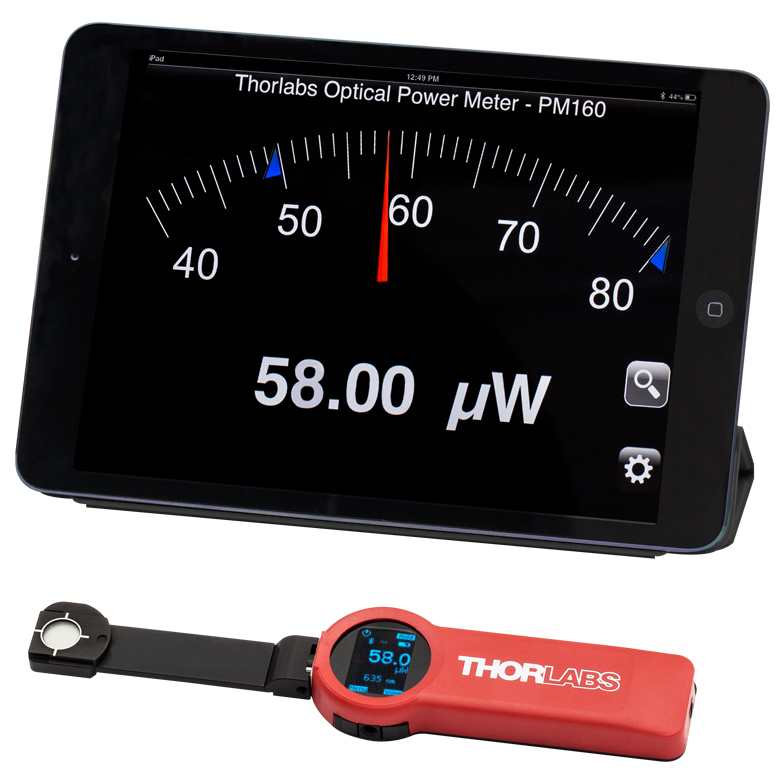
Click to Enlarge
Figure 113A The PM160 wireless power meter, shown here with an iPad mini (not included), can be remotely operated using Apple mobile devices.
This tab outlines the full selection of Thorlabs' power and energy sensors. Refer to Table 113B for power meter console and interface compatibility information.
In addition to the power and energy sensors listed below, Thorlabs also offers all-in-one, wireless, handheld power meters and compact USB power meter interfaces that contain either a photodiode or a thermal sensor, as well as power meter bundles that include a console, sensor head, and post mounting accessories.
Thorlabs offers four types of sensors:
- Photodiode Sensors: These sensors are designed for power measurements of monochromatic or near-monochromatic sources, as they have a wavelength dependent responsivity. These sensors deliver a current that depends on the input optical power and the wavelength. The current is fed into a transimpedance amplifier, which outputs a voltage proportional to the input current.
- Thermal Sensors: Constructed from material with a relatively flat response function across a wide range of wavelengths, these thermopile sensors are suitable for power measurements of broadband sources such as LEDs and SLDs. Thermal sensors deliver a voltage proportional to the input optical power.
- Thermal Position & Power Sensors: These sensors incorporate four thermopiles arranged as quadrants of a square. By comparing the voltage output from each quadrant, the unit calculates the beam's position.
- Pyroelectric Energy Sensors: Our pyroelectric sensors produce an output voltage through the pyroelectric effect and are suitable for measuring pulsed sources, with a repetition rate limited by the time constant of the detector. These sensors will output a peak voltage proportional to the incident pulse energy.
| Table 113B Console Compatibility | ||||||||
|---|---|---|---|---|---|---|---|---|
| Console Item # | PM100A | PM100D | PM400 | PM5020 | PM101 Series |
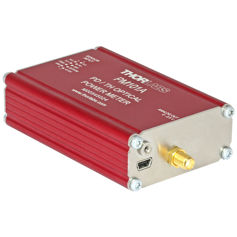
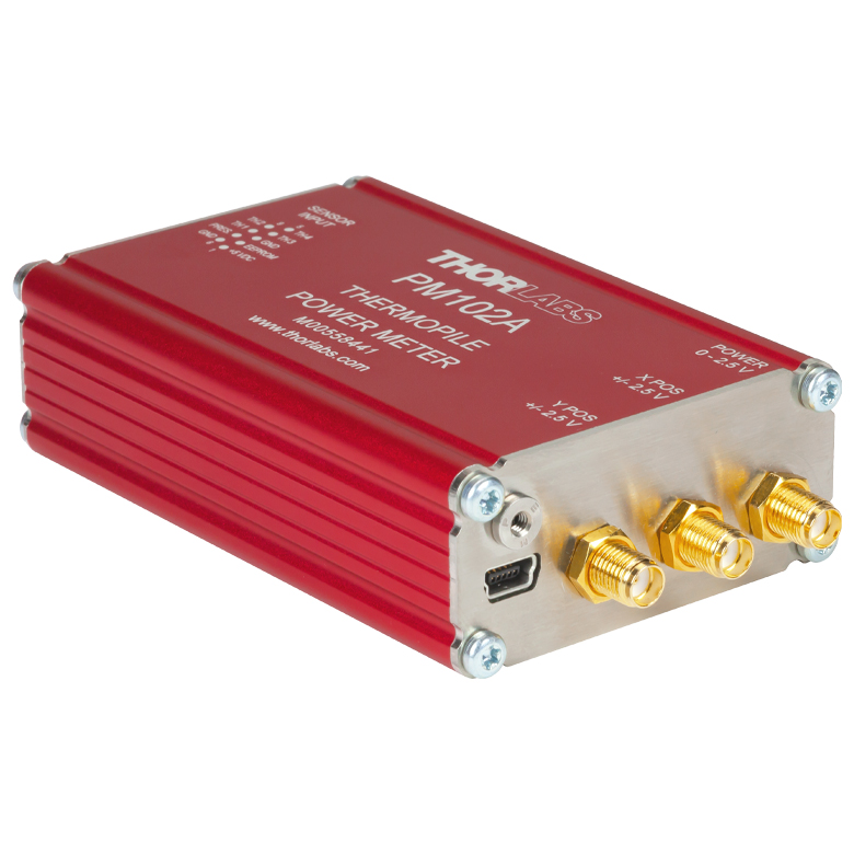
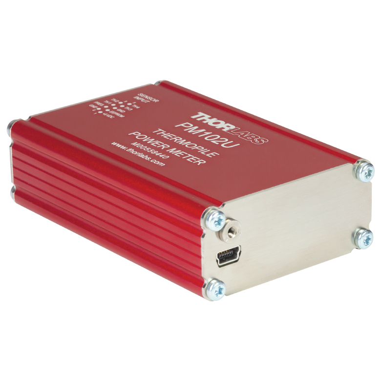
PM102 Series |
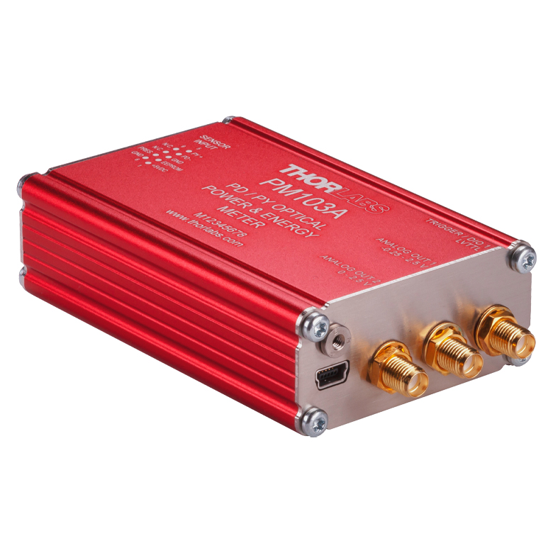
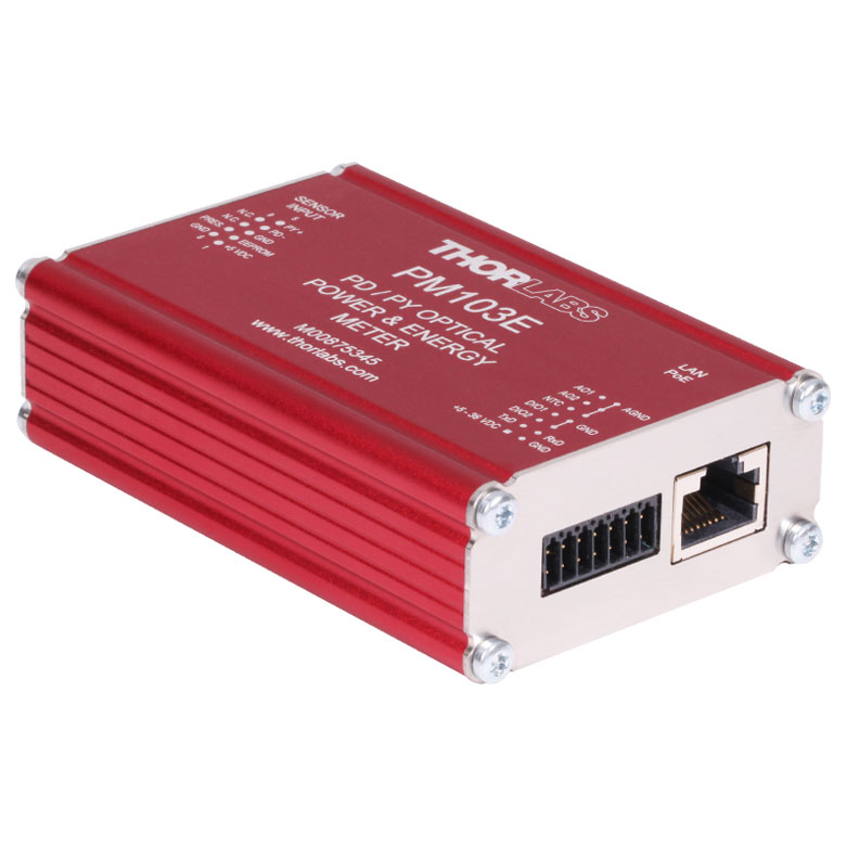
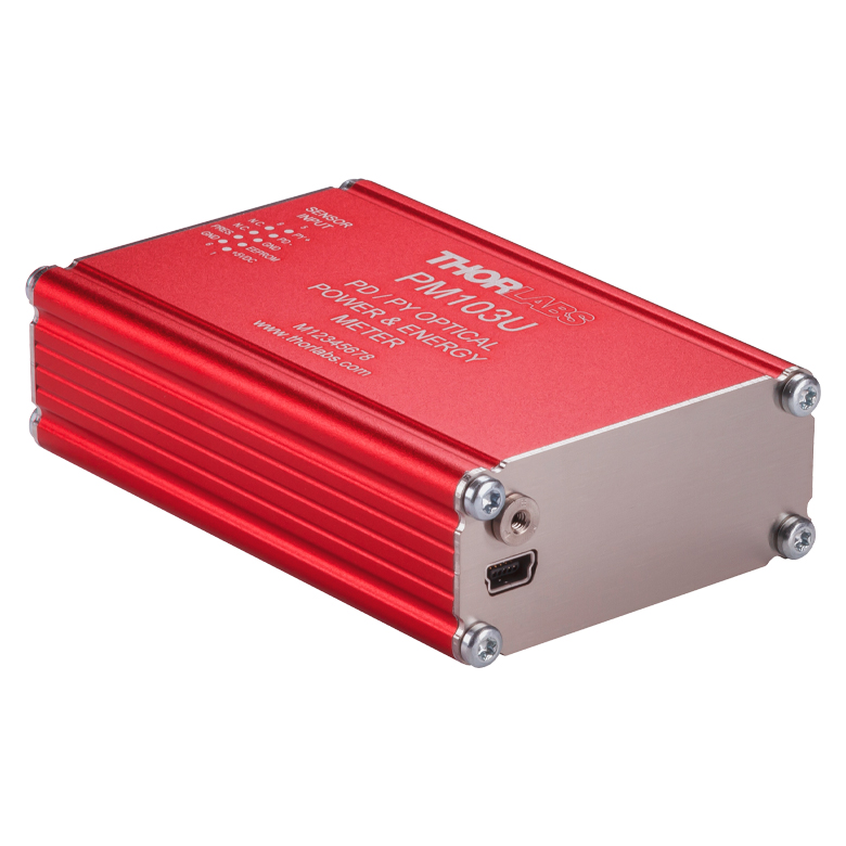
PM103 Series |
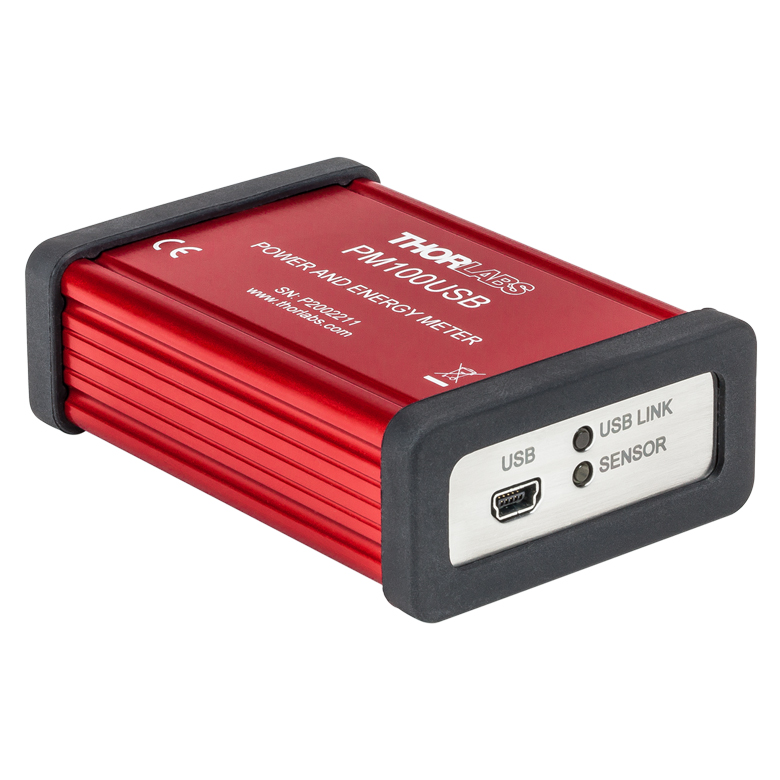
PM100USB |
| Photodiode Power |  |
|
|
|
|
- | |
|
| Thermal Power | |
|
|
|
|
|
- | |
| Thermal Position | - | - | |
|
- | |
- | - |
| Pyroelectric Energy | - | a |
a |
|
- | - | |
a |
Power and Energy Sensor Selection Guide
There are two options for comparing the specifications of our Power and Energy Sensors. Tables 113C, 113D, 113E, and 113F sort our sensors by type (e.g., photodiode, thermal, or pyroelectric) and provide key specifications.
Alternatively, the selection guide Figures 113G and 113H arrange our entire selection of photodiode and thermal power sensors by wavelength (Figure 113G) or optical power range (Figure 113H). Each box contains the item # and specified range of the sensor. These graphs allow for easy identification of the sensor heads available for a specific wavelength or power range.
| Table 113C Photodiode Power Sensors |
|---|


| Table 113D Thermal Power Sensors |
|---|


| Table 113E Thermal Position & Power Sensors |
|---|

| Table 113F Pyroelectric Energy Sensors |
|---|


 Figure 113G Sensor Options Arranged by Wavelength Range
 Figure 113H Sensor Options Arranged by Power Range