Fiber-Coupled Laser Sources: Visible, with TEC
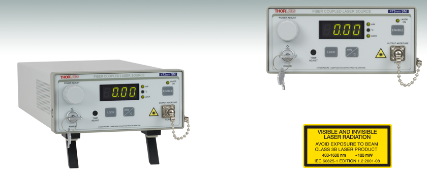
The High-Power Laser Source Front Panel Provides an Enable Button, Display Screen, and Laser Power and Temperature Control
- FC/PC Interface for Single Mode Fiber
- Maximum Output Powers of up to 70 mW
- Stable Output with Temperature Control
S4FC473
473 nm, 20 mW

Please Wait
| Table 1.1 Single Channel Benchtop Laser Sources Selection Guide | |||||
|---|---|---|---|---|---|
| Spectrum | Wavelength | TEC | Laser Type | Cavity Type | Output Fiber Type |
| Visible | 405 - 675 nm | No | Semiconductor | Fabry Perot | SM, MM, or PM |
| 405 - 685 nm | Yes | Semiconductor | Fabry Perot | SM | |
| NIR | 785 - 1550 nm | No | Semiconductor | Fabry Perot | SM or PM |
| 705 - 2000 nm | Yes | Semiconductor | Fabry Perot | SM | |
| 1310 - 1550 nm | Yes | Semiconductor | DFB | SM | |
| 1900 - 2000 nm | N/A | Fiber Laser | Fabry Perot | SM | |
| MIR | 2.7 µm | N/A | Fiber Laser | Fabry Perot | SM |
| Other Fiber-Coupled Laser Sources | |||||
Features
- Two Types of Fabry-Perot Laser Sources
- Standard Sources for 405 or 473 nm
- High-Power Sources for 473 to 685 nm with Improved Output Stability and Software Control
- Single Mode, FC/PC Fiber Interface
- Constant Current Operation
- Power Level is Adjustable via Knob and BNC Modulation Input
- Interlock Circuit Provided via 2.5 mm Mono Jack
Thorlabs offers two types of fiber-coupled laser sources with temperature control. The Fabry-Perot Laser Sources with TEC are offered at a wavelength of 405 nm or 473 nm. The High-Power Fabry-Perot Laser Sources with TEC are offered with seven different wavelengths, ranging from 473 nm to 685 nm, and include a software package to control settings and display features. See Table 1.2 for details regarding each type.
The front panel of each FP laser source with TEC includes a display that shows the output power in mW or the temperature in °C, an on/off key, an enable button, a knob to adjust the laser power (drive current), and a remote interlock input (2.5 mm mono jack) for added safety. The standard FP sources have a knob to adjust the temperature (TEC current), while the high-power FP sources have a trimpot to adjust the temperature. The back panel includes a BNC input that allows the laser diode drive current to be controlled via an external voltage source (0 - 5 V) and a remote interlock input. This input enables intensity modulation of the laser source. The high-power FP laser sources permit a maximum modulation frequency up to 100 kHz using a sine wave. A USB connector on the back panel enables computer communication. The included GUI provides control and readout of the laser's output power and setpoints (see Software tab).
The FP laser diode inside each laser source is pigtailed to a single mode fiber that is terminated at an FC/PC bulkhead connector (wide and narrow key compatible) on the front panel. To minimize losses, we recommend using a fiber patch cable that is the same fiber type as the fiber-pigtailed laser.
Please refer to Table 1.1 for all of our single channel benchtop laser sources. For applications that require several laser sources, consider the temperature-stabilized four-channel fiber coupled laser source.
| Common Specifications | |||||
|---|---|---|---|---|---|
| Driver | |||||
| Power Stability | 15 min: ±0.05 dB, 24 hr: ±0.1 dB (After 1 hr Warm-up at 25 ± 10 °C Ambient) |
||||
| Display Accuracy (mW) | ±10% of Actual | ||||
| Setpoint Resolution | 0.01 mW | ||||
| Adjustment Range | ~0 mW to Full Power | ||||
| TEC | |||||
| Stability | 0.005 °C / 1 °C | ||||
| Setpoint Accuracy | ±0.25 °C | ||||
| Setpoint Resolution | ±0.1 °C | ||||
| Adjustment Range | 20 ± 1 °C to 30 ± 1 °C | ||||
| Environmental | |||||
| Operating Temperature | 15 to 35 °C | ||||
| Storage Temperature | 0 to 50 °C | ||||
| Input Power | 115/230 VAC (Switch Selectable), 50 - 60 Hz | ||||
| Modulation Input | 0 - 5 V = 0 - Full Power, DC or Sinewave Input Only |
||||
| Modulation Input Impedance | 50 Ω | ||||
| Modulation Bandwidth | 5 kHz Full Depth of Modulation 30 kHz Small Signal Modulation |
||||
| High-Power FP Laser Source with TEC Specifications | ||||||||
|---|---|---|---|---|---|---|---|---|
| Item # | S4FC473 | S4FC488 | S4FC520 | S4FC637 | S4FC642 | S4FC660 | S4FC685 | |
| Wavelength | Minimum | 463 nm | 478 nm | 510 nm | 627 nm | 632 nm | 648 nm | 675 nm |
| Typical | 473 nm | 488 nm | 520 nm | 637 nm | 642 nm | 658 nm | 685 nm | |
| Maximum | 483 nm | 498 nm | 530 nm | 647 nm | 652 nm | 668 nm | 695 nm | |
| Spectruma | ||||||||
| Full Output Powerb |
Minimum | 18 mW | 16 mW | 13 mW | 65 mW | 15 mW | 45 mW | 13 mW |
| Typical | 20 mW | 18 mW | 15 mW | 70 mW | 20 mW | 50 mW | 15 mW | |
| Laser Class | 3B | |||||||
| Laser Power Stabilityc |
15 min | ≤0.022 dB (≤0.5%) |
≤0.022 dB (≤0.5%) |
≤0.009 dB (≤0.2%) |
≤0.004 dB (≤0.1%) |
≤0.009 dB (≤0.2%) |
≤0.004 dB (≤0.1%) |
≤0.022 dB (≤0.5%) |
| 24 hr | ≤0.087 dB (≤2.0%) |
≤0.087 dB (≤2.0%) |
≤0.043 dB (≤1.0%) |
≤0.009 dB (≤0.2%) |
≤0.009 dB (≤0.2%) |
≤0.009 dB (≤0.2%) |
≤0.087 dB (≤2.0%) |
|
| Internal Fiber | 460HP | SM600 | ||||||
| Output Fiber Connector | FC/PC, 2.2 mm Wide-Key Slot | |||||||
| Common Specifications | ||||||||
|---|---|---|---|---|---|---|---|---|
| Driver | ||||||||
| Display Accuracy (mW) | ±5% of Actual | |||||||
| Laser Adjustment Range |
Default Setting | Laser Threshold to Max | ||||||
| Optional Setting | 0 mA Current to Max | |||||||
| Laser Adjustment Resolution | 0.01 mW (While Laser is Enabled) | |||||||
| Temperature Adjustment Range | 20 °C to 30 °C | |||||||
| Temperature Setpoint Resolution | 0.01 °C | |||||||
| Modulation Inputa | 0 to 5 V (0 to Full Power) | |||||||
| Modulation Input Impedance | 1 kΩ | |||||||
| Modulation Input Connectorb | BNC | |||||||
| Modulation Bandwidthc | ≤100 kHz, Sine Wave | |||||||
| General | ||||||||
| Operating Temperature | 15 to 35 °C | |||||||
| Storage Temperature | 0 to 50 °C | |||||||
| Input Power | 85 - 264 VAC, 50 - 60 Hz | |||||||
| USB Connectorb | Type B | |||||||
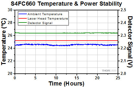
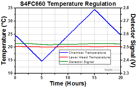
The stability data pertains to our high-power FP laser sources with TEC, and was obtained using an S4FC660 Laser Source. The performance is representative of our other S4FC sources.
Click to Enlarge
A demonstration of the long-term stability of the S4FC660 Laser source, shown over the course of 25 hours. The device is capable of maintaining a constant laser diode temperature, and thus constant output power, over long periods of operation. To obtain the detector signal, the S4FC660 output power was set to 75% of maximum and passed through ND filters reducing the power to 1 mW. The resultant beam was directed into a DET100A (previous generation) detector which was then connected to an oscilloscope via a T-adapter and high-impedance terminator.
Click to Enlarge
The graph above demonstrates the ability of the S4FC660 to maintain steady temperature regulation even with large changes in the environmental temperature. Even when the environment changes by 20 °C, the S4FC660 is able to maintain a steady and regulated temperature of the laser diode, yielding a consistent power output. To obtain the detector signal, the S4FC660 output power was set to 75% of maximum and passed through ND filters reducing the power to 1 mW. The resultant beam was directed into a DET100A (previous generation) detector which was then connected to an oscilloscope via a T-adapter and high-impedance terminator.
Modulation In
BNC Female
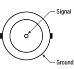
0 to 5 V Max,
50 Ω (S3FC Sources)
1 kΩ (S4FC Sources)
Remote Interlock Input
2.5 mm Mono Phono Jack

Terminals must be shorted either by included plug or user device, i.e. external switch, for laser mode "ON" to be enabled.
USB
USB Type B
Computer Interface
(S4FC Sources)
Click to Enlarge
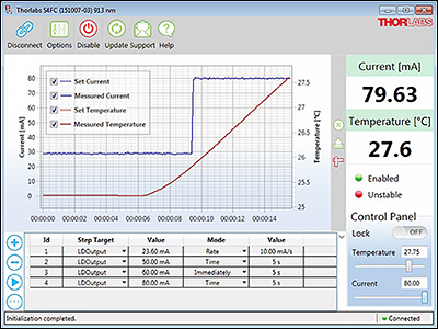
Figure G5.1 S4FC GUI Interface
S4FC Software Package
This software is available only for our S4FC high-power FP laser sources. Our other FP sources cannot be operated by a GUI.
Software
Version 2.0.1
Includes a GUI for control of Thorlabs S4FC Benchtop Laser Sources. To download, click the button below.
GUI Interface
The S4FC software package allows the user to control settings and display features of the benchtop laser source. The package enables several helpful features for controlling the device including setting an output limit, starting the device from the last setting (instead of at 0 mW or threshold power), adjusting the device by current (instead of mW), dimming the display intensity, or enabling the temperature LED to blink when the device is not at its temperature setpoint (making it visually easier to observe when the laser is not at thermal equilibrium). Additionally, the GUI may be utilized to select the temperature setpoint and power output of the device, as well as enabling the laser's output.
Laser Safety and Classification
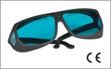
Safe practices and proper usage of safety equipment should be taken into consideration when operating lasers. The eye is susceptible to injury, even from very low levels of laser light. Thorlabs offers a range of laser safety accessories that can be used to reduce the risk of accidents or injuries. Laser emission in the visible and near infrared spectral ranges has the greatest potential for retinal injury, as the cornea and lens are transparent to those wavelengths, and the lens can focus the laser energy onto the retina.
Safe Practices and Light Safety Accessories
- Laser safety eyewear must be worn whenever working with Class 3 or 4 lasers.
- Regardless of laser class, Thorlabs recommends the use of laser safety eyewear whenever working with laser beams with non-negligible powers, since metallic tools such as screwdrivers can accidentally redirect a beam.
- Laser goggles designed for specific wavelengths should be clearly available near laser setups to protect the wearer from unintentional laser reflections.
- Goggles are marked with the wavelength range over which protection is afforded and the minimum optical density within that range.
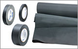
- Laser Safety Curtains and Laser Safety Fabric shield other parts of the lab from high energy lasers.
- Blackout Materials can prevent direct or reflected light from leaving the experimental setup area.
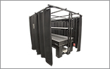
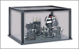
- Thorlabs' Enclosure Systems can be used to contain optical setups to isolate or minimize laser hazards.
- A fiber-pigtailed laser should always be turned off before connecting it to or disconnecting it from another fiber, especially when the laser is at power levels above 10 mW.
- All beams should be terminated at the edge of the table, and laboratory doors should be closed whenever a laser is in use.
- Do not place laser beams at eye level.
- Carry out experiments on an optical table such that all laser beams travel horizontally.
- Remove unnecessary reflective items such as reflective jewelry (e.g., rings, watches, etc.) while working near the beam path.
- Be aware that lenses and other optical devices may reflect a portion of the incident beam from the front or rear surface.
- Operate a laser at the minimum power necessary for any operation.
- If possible, reduce the output power of a laser during alignment procedures.
- Use beam shutters and filters to reduce the beam power.
- Post appropriate warning signs or labels near laser setups or rooms.
- Use a laser sign with a lightbox if operating Class 3R or 4 lasers (i.e., lasers requiring the use of a safety interlock).
- Do not use Laser Viewing Cards in place of a proper Beam Trap.
Laser Classification
Lasers are categorized into different classes according to their ability to cause eye and other damage. The International Electrotechnical Commission (IEC) is a global organization that prepares and publishes international standards for all electrical, electronic, and related technologies. The IEC document 60825-1 outlines the safety of laser products. A description of each class of laser is given below:
| Class | Description | Warning Label |
|---|---|---|
| 1 | This class of laser is safe under all conditions of normal use, including use with optical instruments for intrabeam viewing. Lasers in this class do not emit radiation at levels that may cause injury during normal operation, and therefore the maximum permissible exposure (MPE) cannot be exceeded. Class 1 lasers can also include enclosed, high-power lasers where exposure to the radiation is not possible without opening or shutting down the laser. |  |
| 1M | Class 1M lasers are safe except when used in conjunction with optical components such as telescopes and microscopes. Lasers belonging to this class emit large-diameter or divergent beams, and the MPE cannot normally be exceeded unless focusing or imaging optics are used to narrow the beam. However, if the beam is refocused, the hazard may be increased and the class may be changed accordingly. |  |
| 2 | Class 2 lasers, which are limited to 1 mW of visible continuous-wave radiation, are safe because the blink reflex will limit the exposure in the eye to 0.25 seconds. This category only applies to visible radiation (400 - 700 nm). |  |
| 2M | Because of the blink reflex, this class of laser is classified as safe as long as the beam is not viewed through optical instruments. This laser class also applies to larger-diameter or diverging laser beams. |  |
| 3R | Class 3R lasers produce visible and invisible light that is hazardous under direct and specular-reflection viewing conditions. Eye injuries may occur if you directly view the beam, especially when using optical instruments. Lasers in this class are considered safe as long as they are handled with restricted beam viewing. The MPE can be exceeded with this class of laser; however, this presents a low risk level to injury. Visible, continuous-wave lasers in this class are limited to 5 mW of output power. |  |
| 3B | Class 3B lasers are hazardous to the eye if exposed directly. Diffuse reflections are usually not harmful, but may be when using higher-power Class 3B lasers. Safe handling of devices in this class includes wearing protective eyewear where direct viewing of the laser beam may occur. Lasers of this class must be equipped with a key switch and a safety interlock; moreover, laser safety signs should be used, such that the laser cannot be used without the safety light turning on. Laser products with power output near the upper range of Class 3B may also cause skin burns. |  |
| 4 | This class of laser may cause damage to the skin, and also to the eye, even from the viewing of diffuse reflections. These hazards may also apply to indirect or non-specular reflections of the beam, even from apparently matte surfaces. Great care must be taken when handling these lasers. They also represent a fire risk, because they may ignite combustible material. Class 4 lasers must be equipped with a key switch and a safety interlock. |  |
| All class 2 lasers (and higher) must display, in addition to the corresponding sign above, this triangular warning sign. |  |
|
| Posted Comments: | |
user
(posted 2022-06-11 15:58:00.417) What is the frequency of relaxation oscillation of S4FC637? cdolbashian
(posted 2022-06-24 03:36:04.0) Thank you for reaching out to us with this inquiry. Unfortunately, we do not have this data though I have contacted you directly for a potential solution. trose
(posted 2016-10-13 09:23:29.98) What is the input impedance of the modulation input on the S4FC637? We need to drive it with ±5mA. The S3FC473 had an impedance of 50Ohm, meaning that we had to install a buffer amp to be able to do power modulation using our National Instruments DAQ hardware.
Tobias Rose jlow
(posted 2016-10-13 02:51:27.0) Response from Jeremy at Thorlabs: The input impedance for the S4FC637 is 1kOhm. It can be found in the pin diagram tab but we will make this clearer on the web. |

- Available Wavelengths: 405 nm and 473 nm
- Typical Maximum Output Powers up to 20 mW
- Stabilities of ±0.05 dB Over 15 Minutes
- Fiber Patch Cables Sold Separately
- BNC Connector for Modulating Output with Analog Input
- Thermoelectric Cooler (TEC) for Temperature Stabilization to within 0.005 °C
- Custom Wavelengths Available; Contact Tech Support
These Fiber-Coupled Laser Sources have an integrated TEC element that is used to stabilize the temperature of the FP laser diode, which in turn stabilizes the output power and wavelength of the laser diode for a given drive current.
The FC/PC bulkhead connector is located on the front panel. Also on the front panel is a display that shows the output power in mW or the temperature in °C, an on/off key, an enable button, a knob to adjust the laser power (drive current), and a knob to adjust the temperature (TEC current). The back panel includes an input that allows the laser diode drive current to be controlled via an external voltage source (0 - 5 V) and a remote interlock input. For applications that require several laser sources, consider the temperature-stabilized four-channel fiber coupled laser source.
Note: The laser must be off when connecting or disconnecting fibers from the device, particularly for power levels above 10 mW.

Click to Enlarge
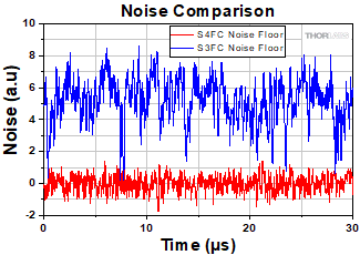
Figure G2.1 An illustration of the difference in the intensity noise floor of an S3FC source compared to an S4FC source. The noise signal from the S4FC laser shows a considerable reduction in the peak-to-peak noise amplitude as well as suppression of high frequency components that are seen in the noise signal of the S3FC laser. The S3FC plot was vertically offset in order to better compare the two signals.
- Available Wavelengths: 473 nm, 488 nm, 520 nm, 637 nm, 642 nm, 660 nm, and 685 nm
- Typical Maximum Output Powers up to 70 mW
- Stabilities of ≤0.022 dB Over 15 Minutes at 75% Max Output Power
- Fiber Patch Cables Sold Separately
- BNC Connector for Modulating Output with Analog Input
- High-Current TEC for Temperature Regulation and Stability
- USB Connector for Computer Control via Included GUI or Command Line
Thorlabs' High-Power Fiber-Coupled Laser Sources are high-performance benchtop Fabry-Perot laser diode sources offering excellent stability and computer control. The internal electronics isolate the laser diode driver from noise coupling (such as that produced by nearby switching supplies). This results in laser sources with lower noise intensity compared to our standard FP Sources with TEC above (see Figure G2.1). The integrated, high-current TEC element can provide excellent temperature regulation and stability to the laser diode, as illustrated in the graphs on the Temp. Stability tab. Even when the ambient temperature changes significantly, the temperature control servo is capable of maintaining constant temperature at the laser diode head. This exceptional temperature stability produces a constant and stable power output from the device.
Click to Enlarge
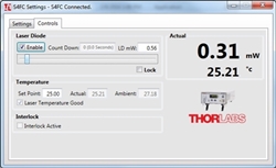
Figure G2.2 The Controls tab of the software when a S4FC Series Benchtop Laser Source is connected and the laser is enabled.
The laser diode is pigtailed to a single mode fiber that is terminated at an FC/PC bulkhead connector (wide and narrow key compatible) on the front panel. Also found on the front panel is a display that shows the output power in mW or the temperature in °C, an on/off key, an enable button, a knob to adjust the laser power (drive current), and a trimpot to adjust the temperature (TEC current).
The back panel includes a BNC input that allows the laser diode drive current to be controlled via an external voltage source (0 - 5 V) and a remote interlock input. This input enables intensity modulation of the laser source. Using a sine wave, the output can obtain full-depth modulation at frequencies up to 100 kHz. A USB connector on the back panel enables computer communication. The included GUI provides control and readout of the laser's output power and setpoints (see Software tab). The back panel also features a remote interlock input (2.5 mm mono jack) for added safety.
Note that the fiber bulkhead and patch cable ferrule must be cleaned prior to connecting a patch cable. For instructions, please refer to the operating manual. The laser must be off when connecting or disconnecting fibers from the device, particularly for power levels above 10 mW. For applications that require several laser sources, consider the temperature-stabilized four-channel fiber coupled laser source.
 Products Home


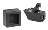

 Zoom
Zoom
 Fabry-Perot Laser Sources with TEC